Abstract
Based on the well-established theoretical formulations of CitationCalvert (1970) and CitationYung et al. (1978), graphical tools are developed for estimating the overall collection efficiency of venturi scrubbers under the specified design and operating conditions. Both graphical solutions deliver the accuracy of the original theoretical models, subject to the assumption of a lognormal input particle size distribution. The nomographs produced can be used by environmental engineers for performing convenient analysis of venturi performance and alternative design evaluations, and as part of a wider methodology for compiling particulate matter emission inventories. Combined with the graphical models developed in Part II, the present work sets the stage for conducting size-specific emission inventories (e.g., PM 2.5 , PM 10 , TPM) for sources controlled by venturi scrubbers.
NOMENCLATURE
| A | = |
cross-sectional area of the scrubber throat, m2 |
| A S | = |
dimensionless parameter defined by Equation (Equation24) |
| Bf | = |
dimensionless parameter defined by Equation (Equation17) |
| B u | = |
dimensionless parameter defined by Equation (Equation25) |
| C c | = |
Cunningham slip-correction factor, defined by Equation (Equation49) |
| C D | = |
drag coefficient, obtained from Equation (Equation2) |
| C D1 | = |
drag coefficient at the throat inlet, obtained from Equation (Equation11) |
| d i | = |
particle diameter belonging to ith size class, μ m |
| d iα | = |
aerodynamic particle diameter belonging to ith size class, μ m |
| d m | = |
mass median diameter of the lognormal particle size distribution, μ m |
| d mα | = |
aerodynamic mass median diameter of particles in the input stream, μ m |
| D | = |
liquid drop diameter, computed in Equation (Equation4), m |
| Ef | = |
overall efficiency |
| Ef i | = |
fractional efficiency |
| E S | = |
dimensionless parameter, defined by Equation (Equation33) |
| f | = |
correlative parameter, dimensionless |
| G c | = |
parameter defined by Equation (Equation20) |
| G u | = |
parameter defined by Equation (Equation46) |
| Int(κ) | = |
parameter defined by Equation (Equation38) |
| K i | = |
inertial parameter defined by Equation (Equation5), dimensionless |
| K n | = |
Knudsen number defined by Equation (Equation50) |
| L t | = |
length of the venturi scrubber throat, m |
| M g | = |
gas molecular weight |
| M o | = |
cumulative fraction-less-than-size d i |
| N Re | = |
Reynolds number, defined by Equation (Equation3), dimensionless |
| P | = |
overall penetration, fractional |
| P g | = |
gas pressure, atm |
| Q g | = |
volumetric gas flow rate, actual m3/s |
| Q L | = |
volumetric liquid flow rate, actual m3/s |
| t | = |
variate defined by Equation (Equation15) |
| T g | = |
gas temperature, °K |
| u de* | = |
ratio of droplet velocity at the exit of the throat to gas velocity in the throat, computed in Equation (Equation9), dimensionless |
| v g | = |
gas velocity, m/sec |
| v gt | = |
gas velocity in the throat, m/sec |
| Greek Letters | = | |
| α | = |
parameter defined by Equation (Equation8) |
| β1 | = |
angle of venturi converging section, , rad |
| β2 | = |
angle of venturi diverging section, , rad |
| γ | = |
parameter defined by Equation (Equation34) |
| κ | = |
integer number of exponential series term |
| μ g | = |
gas viscosity, kg/m-s |
| π | = |
dimensionless constant, 3.14159 |
| ρ g | = |
gas density, computed in Equation (Equation47), kg/m3 |
| ρ L | = |
liquid density, kg/m3 |
| ρ p | = |
particle density, kg/m3 |
| σ g | = |
geometric standard deviation of the lognormal particle size distribution |
| σ | = |
liquid surface tension, N/m |
| ψκ | = |
parameter defined by Equation (Equation42) |
INTRODUCTION
Recent studies on the adverse effects of atmospheric particulate concentrations demonstrate a significant impact in the morbidity and mortality of people and connect these to concentrations of particles with diameters less than 10 and/or 2.5 μ m (PM10 and/or PM2.5) rather than to particles of greater size. Since the early 1990s and in light of these findings, many countries, including the United States and European Union Member-States, have introduced new short-and long-term ambient air quality standards targeted at controlling fine particulates. As safe threshold limits cannot be established for complete protection against health adverse effects of fine particulates, the World Health Organization (WHO) recommends their maximum possible reduction and for the first time introduces guideline values for PM2.5 and PM10 ambient concentrations, which if achieved, are expected to result in significantly reduced health risks (CitationWHO 2005).
The above have created an increasing demand for size-specific emission inventories in addition to these for total particulate matter. To address this need, a practical methodology has been developed, which can be used by planners for compiling fast and credible PM2.5, PM6, PM10, PM15, PM30, and/or TPM inventories for sources with lognormal particle size distributions (CitationEconomopoulou and Economopoulos 2001). For the application of this methodology one needs a set of nomographs that yield the overall efficiency and the size distribution of penetrating particles for each type of control system used. So far, the required nomographs have been developed for dry cyclone separators (CitationEconomopoulou and Economopoulos 2002a and 2002b).
The objective in this article is to deal with venturi scrubbers, which operate on the principle of accelerating the gas through a restriction to give good inertial collection of the particles onto droplets distributed in the gas stream. These relatively simple and robust systems are used extensively in industry for the removal of fine particulate matter and gaseous pollutants from flue gases. They can handle high-temperature, moisture-laden and/or corrosive gases with sticky particles, they can remove simultaneously dust and gaseous pollutants, and they can treat large volumes of gases with small initial investment costs compared to electrostatic precipitators. Major drawbacks are the high gas pressure drops, and hence high operating costs, which are required for high dust removal efficiencies and the liquid effluents and sludges that are generated and require proper management.
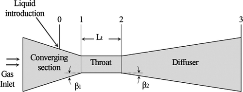
The most common types of venturi scrubbers are: (a) the pre-formed spray type, where drops are formed by atomizer nozzles directed at the throat and injected into the gas stream, and; (b) the gas-atomized spray type, where liquid is introduced in bulk ahead of the venturi throat and shattered into drops by the high-velocity gas. In the latter type, often referred to as “wetted approach” type, the liquid is introduced to the scrubber through tangential pipes in the converging section. A typical outline for these types of venturi scrubbers is given in , with the various sections designated.
FIG. 1 Venturi scrubber configuration: 0–1: converging section, 1–2: throat, 2–3: diverging section; point 0 where liquid is introduced, may coincide with point 1.
As venturi scrubbers have been a popular choice among gas cleaning devices, several modeling attempts have been made to predict successfully their fractional collection efficiency (collection efficiency of a given particle size) and gas pressure drop.
The main objective of the present work is to select well-established theoretical models from literature, and to use them for developing graphical tools for fast and rigorous estimation of the overall collection efficiency under the specified venturi scrubber design and operating conditions. The generated nomographs are applicable for sources with log-normal particle size distributions and can be used by environmental designers and planners for compiling credible size-specific particulate emission inventories for sources controlled by venturi scrubbers.
The above graphical tools could be used also in the design of venturi scrubber systems. In this, collection efficiencies need to be balanced against gas pressure drops and the related electric power costs. To accomplish this task, designers can follow an iterative procedure, in the context of which, the TPM and PMx removal efficiencies can be conveniently assessed through the graphical solution offered and the gas pressure drop can be computed though appropriate pressure drop relations selected from the literature.
COLLECTION EFFICIENCY AND PRESSURE DROP MODELS
The collection efficiency of a venturi scrubber is affected by numerous mechanisms operating simultaneously. These include inertial impaction and interception, and to a lesser degree, diffusion, electrostatics, nucleation and growth, and condensation. Inertial impaction is the predominant mechanism for removing particles with diameter larger than 0.5 μ m, while diffusional collection prevails for particles with diameters smaller than 0.1 μm. Each of these forces contribute its share to the fractional efficiency Ef i , defined as the collection efficiency of particles with given diameter d i .
To evaluate the fractional efficiency of venturi scrubbers, two alternative modeling approaches are selected in our analysis; one developed by CitationCalvert (1970) and the other by CitationYung et al. (1978). They are intended primarily to model venturi scrubbers with liquid injection at the throat, as they do not account for any significant liquid flowing as film on the duct walls. However, they can also be applied on wetted approach type venturi scrubbers with satisfactory predictions.
Calvert's formulation relies on more assumptions compared to other models, but its simplicity and satisfactory predictions has made it very popular among engineers. The formulation of Yung et al. improves Calvert's original model making it independent of any empirical parameters and its predictions have been reported to match closely the experimental data in several studies (e.g., CitationRudnick et al., 1986; CitationPlacek and Peters, 1981; CitationYung et al., 1978). Both models are based on the assumption of a homogeneous core with drops, and the absence of film flow on the wall.
Recent collection efficiency models (e.g., CitationPulley 1997), which make use of more profound fluid mechanics basis developed for predicting the gas pressure drop (e.g., CitationAzzopardi et al. 1991), present significant theoretical and practical interest. However, little work has been published so far to confirm their credibility, and this hinders their widespread use.
For high removal efficiencies, high gas velocities are generally required and hence high pressure drops and energy demands. In view of this, designers are compelled to balance particle removal efficiencies against pressure drops (and the associated operating costs), and for this they use the particle collection efficiency relations along with the gas pressure drop ones.
So far, more than 20 semi-empirical and theoretical formulations have been developed for predicting the gas pressure drop. Among them, the earlier ones were strongly empirical, thus unsuccessful for accurate predictions when tested on industrial scale or under different experimental configurations. The formulations that followed attempted to model the hydrodynamic phenomena occurring in the venturi scrubber and became more popular because they offered improved predictions with simple and explicit algebraic formulae. Among the latter, the models of CitationCalvert (1970), CitationYung et al. (1977), CitationLeith et al. (1985), and CitationBoll (1973) were the most widely quoted ones.
More recently, Azzopardi and his coworkers developed a more sophisticated modeling approach for simulating the gas-liquid flow in venturi scrubbers and predicting the venturi pressure drop (CitationAzzopardi et al. 1991; CitationAzzopardi 1992; CitationAzzopardi et al. 1999; Citationvan Werven et al. 2003; CitationSun and Azzopardi 2003). Their approach provides an elegant insight into the mechanisms at work, accounting, inter alia, for the presence of liquid film on the venturi walls, continual atomization and re-deposition of the liquid on the walls, and boundary layer growth and separation. A similar approach has also been followed by CitationViswanathan (1985) to develop an annular flow pressure drop model.
Fractional Efficiency Model by Calvert
According to Calvert's model, the primary particle collection mechanism is inertial impaction and the flow is one-dimensional, incompressible, and adiabatic. The liquid is introduced at the throat entrance with no axial velocity and inside the throat droplets accelerate to gas velocity (the throat is infinitely long). The liquid drop distribution is uniform across the duct and all liquid atomizes instantaneously into monodisperse droplets, with a Sauter mean diameter, D, predicted from the empirical correlation of CitationNukiyama and Tanasawa (1939).
Based on the above assumptions, Calvert obtained the following expression for the fractional efficiency in a venturi throat, where the relative velocity differences between particles and drops are the highest and where most of the particle collection action occurs:
The variables in Equation (Equation1) are defined in metric units through the following relationships:
The variable f in Equation (Equation1) is an empirical parameter that ranges from 0.2 to 0.7. Calvert recommended a value of 0.25 for the collection of hydrophobic aerosols and a value of 0.5 for the collection of hydrophilic particle materials. Latter studies indicate that f = 0.31 gives a much better fit than f = 0.25 (CitationRudnick et al. 1986). The accurate prediction of parameter f is not possible but, if it is determined in pilot-scale tests for a given system, then this value could be used for scale-up calculations.
Fractional Efficiency Model by Yung et al.
Yung et al. modified Calvert's model by using less restrictive assumptions. As with the Calvert's model, all liquid entering the venturi scrubber atomizes instantaneously into monodisperse droplets with a diameter given by the Nukiyama-Tanasawa Equation (Equation4), but the droplets do not reach the gas velocity at the end of the throat. This formulation leads to the following algebraic fractional efficiency formula, which is more complex than Equation (Equation1), but does not contain the empirical parameter f:
Yung et al. assumed that the ratio of the droplet velocity at the exit of the throat to gas velocity in the throat, u de*, is given by equation:
VENTURI SCRUBBER SIMULATION AND GRAPHICAL ANALYSIS
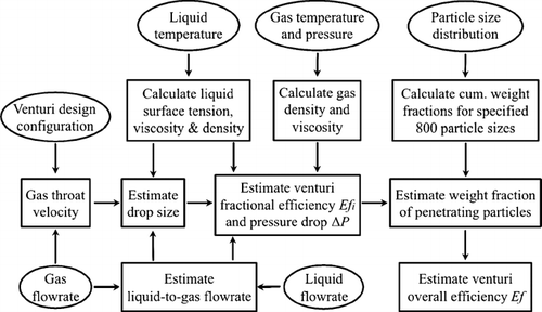
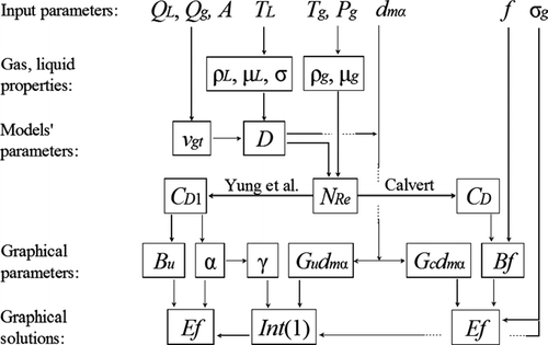
The development of graphical solutions to venturi performance problems started with the development of modules simulating the different theoretical models. These were used for the numerical calculation of the overall collection efficiencies and gas pressure drops under the specified venturi design and operating conditions. The interdependence of numerical calculations and the computation sequence followed by the developed FORTRAN program are shown in the flow diagram of .
To calculate the overall collection efficiency, the mathematical formulations used for predicting the fractional efficiencies by the selected simulated models are numerically integrated over the entire particle size distribution function, as described below. The numerical integration is performed over 800 particle diameter increments ranging from 0.01 to 1000 micrometers, with smaller increments used in the region of small particle sizes. The analysis is performed with log-normal particle size distribution, which can be defined through the mean particle diameter, d m , and the standard deviation, σ g .
The results from the venturi scrubber simulation programs were compared to the theoretical model predictions reported in literature, under identical design and operating conditions, so as to ensure that the developed source codes were free of errors. These programs provide an exact numerical solution of the removal efficiency problem based on the original models, without any simplifying assumptions, and serve as references for validating the accuracy of the graphical solutions.
Calculation of the Overall Efficiency from Fractional Efficiencies
Given the size distribution of particles in terms of a cumulative fraction-less-than-size d i , M o = M o (d i ), (0 < M o < 1) and the fractional efficiency of the collector by an equation such as Ef i = Ef(d i ), the overall efficiency in terms of mass can be calculated by integrating the grade efficiency over the particle size distribution:
The overall penetration can then be expressed as:
A simplifying and commonly used assumption is that the inlet dust particles follow a log-normal distribution. If d m and σ g are the mass median diameter and standard deviation, Equation (Equation13) may be written as follows (e.g., CitationLicht 1988):
It should be noted that the complex relations of any selected grade efficiency model, such as those of CitationCalvert (1970) or CitationYung et al. (1978), constitute an integral part of Equation (Equation14). As a result, Equation (Equation14) cannot be solved analytically and numerical methods have to be employed for estimating the overall penetration.
Graphical Solution of the Calvert Collection Efficiency Model
Introducing Equations (Equation1),(Equation2),(Equation3), (Equation5), and (Equation6) into Equation (Equation14) and rearranging, we obtain the following expression:
Equation (Equation19) is not amenable to a general two-dimensional graphical solution, due to the large number of independent variables involved. To overcome this problem, one can develop a set of graphs, each valid for a fixed value of the parameter Bf. For each such graph, instead of Equation (Equation19), one can solve the following relation:
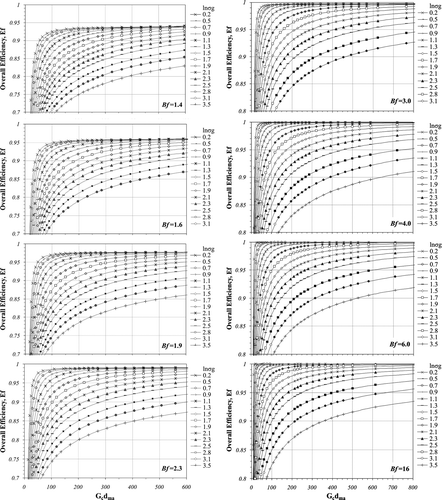
presents a set of graphs with values of the parameter Bf ranging from 1.4 to 16 to cover the entire range of interest. Based on the value of Bf, one can select the appropriate graph and estimate the overall collection efficiency as function of the intermediate parameter G c and the parameters d mα and ln σ g of the lognormal particle size distribution. For intermediate values of Bf, the overall efficiency can be calculated through linear interpolation with negligible error.
Graphical Solution of the Yung et al. Collection Efficiency Model
Introducing the fractional efficiency Equation (Equation7) into (Equation14) we obtain:
To rearrange appropriately the above equation, we use the following mathematical transformations:
Introducing Equations (Equation27), (Equation28), (Equation29), (Equation30) and (Equation31) into Equation (Equation23) and rearranging, we have:
The parameter γ, which appears in the last two terms of Equation (Equation33), ranges from 0.20 to 0.55, under a wide range of venturi scrubber operating conditions. Numerical simulation tests have shown that the use of only three fixed values of parameter γ (for 0.28, 0.40, and 0.49), instead of the actual ones in each case, results in a negligible error in the calculation of the overall penetration, when the standard deviation has medium to low values (σ g < 6.0). If the value of parameter γ is fixed, Equation (Equation33) can be written in the following functional form:
To simplify further the overall efficiency expression, to enable a graphical solution of the venturi design and efficiency prediction problem, we develop the term exp (α0.5 B u ) E S of Equation (Equation32) in the following exponential series:
To proceed with the mathematical analysis, we define parameter ψκ(t) as:
For κ = 1, Equation (Equation39) takes the form:
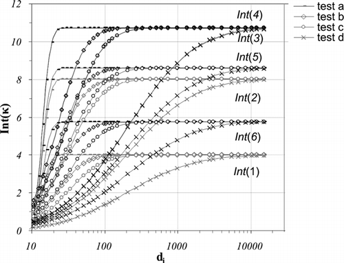
According to Equation (Equation42), each term Int(κ), is a function of parameter ψ1(t), the later being function only of parameters √v gt α/Dμ g d mα and σ g . As defined by Equation (Equation40), the integral of ψ1(t) gives the first series term, Int(1). It has been observed that Int(1) characterizes adequately the combination of parameters √v gt α/Dμ g d mα and σ g , and hence each term Int(κ) can be expressed as:
Parameter κ depends on the number of terms of the exponential series that are used to transform and approximate Equation (Equation36). For infinite number of terms, κ → n, and taking into account Equation (Equation43), Equation (Equation37) can be written in the following functional form:
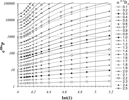
The functional form of Equation (Equation44) is amenable to graphical solution, where the overall venturi penetration parameter e 4B u P, can be estimated through the combined use of the nomographs in and :
| • | The three nomographs in yield the intermediate parameter Int(1), as function of key venturi scrubber operating conditions and the lognormal size distribution parameters, namely the parameters G u d mα and lnσ g . Selection of the appropriate nomograph depends on the value of parameter γ. For intermediate values of the latter, Int(1) can be calculated through linear interpolation with negligible error (for σ g < 6.0). | ||||
| • | The nomograph in , derived through numerical solution of Equation (Equation37), yields the parameter e 4B u P, as function of parameters Int(1) and α0.5 B u , the latter determined from Equations (Equation8) and (Equation25). From the parameter e 4B u P, one can easily estimate the overall penetration P, and the overall efficiency Ef = 1 −P. | ||||
FIG. 4 Parameter Int(1) versus parameters G u d mα and lnσ g , for the graphical solution of the Yung et al. model.
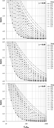
FIG. 5 Venturi overall penetration parameter e 4B u P versus parameter Int(1), for the graphical solution of Yung et al. model.
The graphical model presented according to the Yung et al. formulation is easy to use and gives accurate predictions for medium to low values of the standard deviation of the lognormal particle size distribution. This restriction is associated with the assumption of a constant value of parameter γ within three specified ranges of values. Although the mathematical analysis also uses the exponential series transformation, no error was introduced on this account to the final penetration expression due to the infinite number of series terms selected in the present analysis.
The functional analysis performed to develop the Yung et al. graphical solution, relies on the validity of Equation (Equation43). Analytical proof that each term Int(κ) is only a function of the first term, Int(1), and the integer κ is not available. Proof of this validity can only be produced numerically. For this purpose one can compute numerically the parameter Int(κ) for κ = 1, 2, 3, … using Equation (Equation38), under different operating conditions and various input particle size distribution parameters. For Equation (Equation43) to be valid, all simulation tests, which happen to have the same value of term Int(1), should have identical values in their parameters Int(κ). demonstrates how closely, for different simulation tests, each term Int(κ), κ = 2 – 6, converges to the same value when their first term Int(1) is identical.
GAS DENSITY AND VISCOSITY DATA
The gas density, ρ g , at any given temperature and pressure can be computed from the ideal gas law in the form of Equation (Equation47) below. In this, the gas density at standard conditions, ρ g ]std, is 1.293 and 1.297 for ambient air and for boiler flue gas respectively.
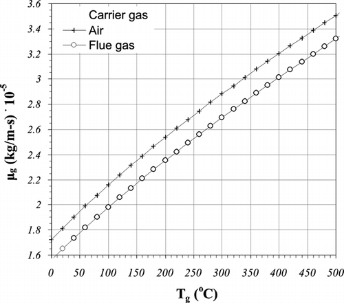
The gas viscosities are calculated as a function of temperature from the relation of CitationNeufeld et al. (1972) and the Lennard-Jones potential coefficients tabulated by CitationReid et al. (1977). The results for ambient air and flue gas with a typical molar composition of O2 = 3.64%, N2 = 75.2%, CO2 = 11.32%, H2O = 9.83%, and SO2 = 0.01% are plotted in the diagram of over the range of 0 to 500°C. The diagram of is applicable over all pressures normally employed in venturi operations, as the gas viscosity is unaffected by pressure at this low pressure range (CitationReid et al. 1977).
AERODYNAMIC PARTICLE DIAMETER
The aerodynamic particle diameter, d iα, used in the theoretical formulations, is related to the actual particle diameter, d i , by the following expression of CitationRaabe (1976):
The Cunningham slip correction factor C c is introduced in order to take into account cases where the particle size is small enough to be of the order of the mean free path of the gas molecules. Under this condition, the gas no longer behaves as a continuous medium with respect to the particle, and its drag effect is reduced. The value of the Cunningham factor, C c , depends upon the ratio of the mean free path of the gas molecules to the size of the particle, expressed as the Knudsen Number. CitationDavies (1945) proposed the following relationship to correlate the above data:
For a perfect gas, the Knudsen Number, K n , is calculated as:
USE OF NOMOGRAPHS
To estimate the overall efficiency of a venturi scrubber through the use of the graphical models developed, input data are required on the venturi scrubber design configuration (A, L t ), the operating conditions (Q g , T g , P g , Q L , T L ) and the particle properties (ρ p , d m , σ g ). Once these data are known, the overall efficiency can be estimated following the simple step-by-step procedure as follows (see also ):
Step 1. Calculate gas and liquid physical properties:
| |||||||||||||||||||||||
Step 2. Calculate model parameters:
| |||||||||||||||||||||||
Step 3a. Graphical solution based on Calvert's formulation:
| |||||||||||||||||||||||
Step 3b. Graphical solution based on Yung et al. formulation:
| |||||||||||||||||||||||
EXAMPLE
Estimate the overall efficiency of a venturi scrubber controlling the particle emissions from an industrial boiler firing spent lubricating oils. The flue gas has a flow volumetric flow rate Q g = 5.0 am3/s at T g = 130°C and P g = 1 atm. The particles in the flue gas have a density ρ p = 2500 kg/m3 and their size distribution is lognormal with d ma = 5.05 μm and σ g = 3.7. The venturi scrubber is a gas-atomized spray type, with liquid introduction at the throat through nozzles at flow rate Q L = 5.5 lt/s. The venturi throat has rectangular geometry of cross-sectional area A = 0.0625 m2 and length L t = 0.80 m.
Solution
Step 1. Calculate gas and liquid physical properties:
| |||||||||||||||||||||||
Step 2. Calculate model parameters:
| |||||||||||||||||||||||
Step 3a. Graphical solution based on Calvert's formulation:
| |||||||||||||||||||||||
Step 3b. Graphical solution based on Yung et al. formulation:
| |||||||||||||||||||||||
Based on the above, the graphically estimated overall efficiencies from the formulations of Calvert and Yung et al. are 0.890 and 0.966 respectively. The graphical results are practically identical to the theoretical models' predictions. The divergence in the predictions depends on the value of the correlative coefficient f used in Calvert's formulation and on the differences in the fractional efficiency versus particle diameter curves generated by the two theoretical formulations. The latter is accentuated in the case of fine particle size distributions, as in our example.
SUMMARY AND CONCLUSIONS
Venturi scrubbers are extensively used in industry for they are compact and simple to build, yet very efficient devices in controlling fine particle emissions. The compilation of TPM and/or PMx emission inventories from venturi scrubber controlled sources entails the use of collection efficiency models, along with scrubber design configuration and operating data from the field. The design of new venturi scrubber systems entails combined use of collection efficiency and gas pressure drop models, enabling designers to properly balance the TPM and/or PMx removal efficiencies against gas pressure drop.
In this article, two well-established collection efficiency models are selected and used for developing graphical solutions that enable convenient assessment of the TPM and/or PMx removal efficiencies. In addition, appropriate gas pressure drop models that can be used in new venturi scrubber design problems are referenced. The collection efficiency models selected and considered in the present article are those of CitationCalvert (1970) and CitationYung et al. (1978) that remain very popular today, despite their age; the former for its reliability and simpler relationships and the latter for the accuracy of its predictions. In particular, the accuracy of Calvert's model depends on the selection of the correlative parameter f. The Yung et al. model is widely used in practice for efficiency predictions and for design purposes, and is often used in literature as reference for other model validations (e.g., CitationPlacek and Peters 1981; CitationCrowder et al. 1982; CitationOtt et al. 1987; CitationPulley 1997).
The graphical solutions developed for the above models perform complex tasks, offering designers and planners the option of working in both directions: from the design configuration of an existing system to the prediction of its performance, or from the desirable performance, in terms of TPM and/or PMx removal efficiency, to the design of a new system. For their development, elaborate software routines were designed that solve the lognormal size distribution function; solve the relations of each fractional efficiency model; integrate numerically the results for estimating the overall efficiency; and compute, through an iterative optimization algorithm, the lognormal distribution function that best-fits the output particle size distribution. Functional analysis makes possible to fit the numerical data produced into nomographs that are valid for any design configurations and operating data combinations.
Use of the above graphical tools enables planners to compile credible emission estimates from sources controlled by venturi scrubbers, without the time-consuming process of developing sophisticated software. The availability of similar nomographs for other important types of dust control systems and the ability to combine their use (CitationEconomopoulou and Economopoulos 2001, Citation2002a, Citation2002b; CitationEconomopoulou and Harrison 2006, 2007a expected and 2007b expected) facilitates the task of compiling particle emission inventories of sufficient quality for effective control strategies formulation and promulgation of control measures.
Both graphical solutions are based on the assumption of lognormal input particle size distribution. The graphical model based on Calvert's formulation has unrestricted applicability. The graphical model based on the formulation of Yung et al. is most accurate for low to medium values of the standard deviation of the lognormal inlet particles distribution (σ g < 6) and its use is recommended in this region. This restriction does not limit significantly the practical use of the proposed graphical solution as the predominant use of venturi scrubbers is with sources emitting fine particles, such as metallurgical, electric power, and nonmetallic mineral manufacturing plants.
Subject to the above conditions, both graphical solutions yield practically identical results with the original theoretical models. To verify this, the results of the graphical solutions were compared, over the entire range of design configurations and operating conditions of interest, with the rigorous solution of the original Calvert and Yung et al. formulations produced by the computer programs described above. The results of the rigorous numerical solutions of both models have been compared with experimental data in various references (e.g., CitationCalvert 1970; CitationRudnick et al. 1986; CitationPlacek and Peters 1981; CitationYung et al. 1978; CitationYung et al. 1977; CitationPulley 1997; CitationCrowder et al. 1982).
Acknowledgments
Alexia A. Economopoulou is a recipient of the C. N. Davies Award, a research scholarship from the UK Aerosol Society.
REFERENCES
- Azzopardi , B. J. 1992 . Gas-Liquid Flows in Cylindrical Venturi Scrubbers: Boundary Layer Separation in the Diffuser Section . Chemical Engineering Journal , 49 : 55 – 64 .
- Azzopardi , B. J. , Teixeira , S. F. C. F. , Govan , A. H. and Bott , T. R. 1991 . An Improved Model for Pressure Drop in Venturi Scrubbers . Trans IChemE, Part B, Proc. Safe Env. Prot. , 69 : 237 – 245 .
- Azzopardi , B. J. , Teixeira , S. F. C. F. and Pulford , C. I. 1999 . A Quasi-One-Dimensional Model for Gas/Solids Flow in Venturis . Powder Technology , 102 : 281 – 288 .
- Boll , R. H. 1973 . Particle Collection and Pressure Drop in Venturi Scrubbers . Ind. Eng. Chem. Fundam. , 12 : 40 – 50 .
- Calvert , S. 1970 . Venturi and Other Atomising Scrubbers Efficiency and Pressure Drop . AICHE Journal , 16 : 392 – 396 .
- Calvert , S. and Englund , H. M. 1984 . Handbook of Air Pollution Technology. , New York : Wiley-Interscience .
- Crowder , J. W. , Noll , K. E. and Davis , W. T. 1982 . Modelling of Venturi Scrubber Efficiency . Atmos. Environ. , 16 : 2009 – 2013 .
- Davies , C. N. 1945 . Definitive Equations for the Fluid Resistance of Spheres . Proc. Phys. Soc. , 57 : 259 – 270 .
- Economopoulou , A. A. and Economopoulos , A. P. 2001 . Method for Estimating Size-Specific Particulate Emission Inventories . J. Environmental Engineering, ASCE , 127 : 1139 – 1148 .
- Economopoulou , A. A. and Economopoulos , A. P. 2002a . Rapid Performance Evaluation and Optimal Sizing of Dry Cyclone Separators . J. Environmental Engineering, ASCE , 128 : 275 – 285 .
- Economopoulou , A. A. and Economopoulos , A. P. 2002b . Size Distribution of Particles Penetrating Dry Cyclone Separators . J. Environmental Engineering, ASCE , 128 : 919 – 928 .
- Economopoulou , A. A. and Harrison , R. M. 2006 . Graphical Analysis of Venturi Scrubbers Part II: Size Distribution of Penetrating Particles. Submitted
- Economopoulou , A. A. and Harrison , R. M. Graphical Analysis of Electrostatic Precipitators (In preparation). Part I: Rapid Collection Efficiency Evaluation
- Economopoulou , A. A. and Harrison , R. M. Graphical Analysis of Electrostatic Precipitators (In preparation). Part II: Size Distribution of Penetrating Particles
- Ingebo , R. D. and Foster , H. H. 1957 . Drop Size Distribution for Cross Current Breakup of Liquid Jets in Air Streams NACA Technical Report 4807
- Leith , D. , Cooper , D. W. and Rudnick , S. N. 1985 . Venturi Scrubbers: Pressure Drop and Regain . Aerosol Sci. Tech. , 4 ( 2 ) : 239 – 243 .
- Licht , W. 1988 . Air Pollution Control Engineering. , New York and Basel : Marcel Dekker, Inc. .
- Neufeld , P. D. , Janzen , A. R. and Aziz , R. A. 1972 . Empirical Equations to Calculate 16 of the Transport Collision Integrals Ω(l,s)* for the Lennard-Jones (12-6) potential . J. Chem. Phys. , 57 : 1100 – 1102 .
- Nukiyama , S. and Tanasawa , Y. 1939 . Experiments on the Atomisation of Liquids in an Airstream . Trans. Soc. Mech. Eng. (Japan) , 5 : 68 – 75 .
- Ott , R. M. , Wu , T. K. L. and Crowder , J. W. 1987 . Modelling of Surface Tension Effects in Venturi Scrubbing . Atmos. Environ. , 21 : 479 – 482 .
- Placek , T. D. and Peters , L. K. 1981 . Analysis of the Particulate Removal in Venturi Scrubbers—Effect of Operating Variables on Performance . AIChE Journal , 27 : 984 – 993 .
- Pulley , R. A. 1997 . Modelling the Performance of Venturi Scrubbers . Chemical Engineering Journal , 67 : 9 – 18 .
- Raabe , O. G. 1976 . Aerosol Aerodynamic Size Conventions for Inertial Sampler Calibration . Air Pollution Control Assoc. J. , 26 : 856 – 860 .
- Reid , R. C. , Prausnitz , J. M. and Sherwood , T. K. 1977 . The Properties of Gases and Liquids. , 3rd Edition , New York : McGraw-Hill .
- Rudnick , S. N. , Koehler , J. L. M. , Martin , K. P. , Leith , D. and Cooper , D. W. 1986 . Particle Collection Efficiency in a Venturi Scrubber: Comparison of Experiments with Theory . Environ. Sci. Technol. Res. , 20 : 237 – 242 .
- Sun , H. and Azzopardi , A. A. 2003 . Modelling Gas-Liquid Flow in Venturi Scrubbers at High Pressure . Trans IchemE , 81 : 250 – 256 .
- van Werven , M. , Ooms , G. , Azzopardi , B. J. and van Maanen , H. R. E. 2003 . Modelling Wet-Gas Annular-Dispersed Flow Through a Venturi . AIChE Journal , 49 : 1383 – 1391 .
- Viswanathan , S. , Gnyp , A. W. and St. Pierre , C. C. 1985 . Annular Flow Pressure Drop for Pease-Anthony Venturi Scrubbers . AIChE Journal , 12 : 1947 – 1958 .
- WHO . 2005 . Air quality guidelines global update 2005. http://www.euro.who.int/Document/E87950.pdfWorld Health Organization, Working Group Meeting Report, (Germany, 18–20 October 2005). Internet Address
- Yung , S. C. , Calvert , S. , Barbarika , H. F. and Sparks , L. E. 1978 . Venturi Scrubber Performance Model . Environ. Sci. Technol. , 12 : 456 – 459 .
- Yung , S. C. , Barbarika , H. F. and Calvert , S. 1977 . Pressure Loss in Venturi Scrubbers . Journal of Air Pollution Control Association, APCA , 27 ( 4 ) : 348 – 350 .
- Yung , S. C. , Calvert , S. and Barbarika , H. F. 1977 . Venturi Scrubber Performance Model EPA Rep. No. 600/2-77-172
