Abstract
Graphical tools are developed that provide convenient estimation of the size distribution of particles penetrating venturi scrubbers, based on the well-established theoretical formulations of CitationCalvert (1970) and CitationYung et al. (1978). The graphical solutions, produced through functional analysis and numerical methods, deliver the accuracy of the original theoretical models under the specified venturi design and operating conditions, subject to the assumption of lognormal input particle size distribution. While Part I describes estimation of the overall particle abatement efficiency, the work in this article allows estimation of the size distribution of emitted particles. The generated nomographs can therefore be used as part of a methodology for compiling size-specific particulate matter emission inventories.
NOMENCLATURE
| A | = |
cross-sectional area of the scrubber throat, m2; |
| Bf | = |
dimensionless parameter defined by Equation (Equation2); |
| B u | = |
dimensionless parameter defined by Equation (Equation16); |
| C c | = |
particle Cunningham slip-correction factor, dimensionless; |
| C D | = |
drag coefficient, obtained from Equation (Equation3); |
| C D1 | = |
drag coefficient at the throat inlet, obtained from Equation (Equation13); |
| d i | = |
particle diameter belonging to ith size class, μ m; |
| d iα | = |
aerodynamic particle diameter belonging to ith size class, μ m; |
| d m | = |
mass median diameter of particles in the input stream, μ m; |
| d mα | = |
aerodynamic mass median diameter of particles in the input stream, μ m; |
| d p | = |
mass median diameter of particles in the output stream, μ m; |
| d pα | = |
aerodynamic mass median diameter of particles in the output stream, μ m; |
| D | = |
liquid drop diameter, computed in Equation (Equation5), m; |
| Ef | = |
overall efficiency; |
| Ef i | = |
fractional efficiency; |
| f | = |
correlative parameter, dimensionless; |
| G c | = |
parameter defined by Equation (Equation8); |
| G u | = |
parameter defined by Equation (Equation17); |
| K i | = |
inertial parameter defined by Equation (Equation6), dimensionless; |
| K n | = |
Knudsen number defined by Equation (Equation20); |
| L t | = |
venturi scrubber throat length, m; |
| M g | = |
molecular weight of gas mixture; |
| M i | = |
mass of particles with diameter less than d i ; |
| N Re | = |
Reynolds number, defined by Equation (Equation4), dimensionless; |
| P | = |
overall penetration, fractional; |
| P i | = |
penetration of a given diameter d i , fractional; |
| P g | = |
gas pressure, atm; |
| PM i | = |
particulate mater with diameter size less than i μ m; |
| Q g | = |
volumetric gas flow rate, actual m3/s; |
| Q L | = |
volumetric liquid flow rate, actual m3/s; |
| T g | = |
gas temperature, °K; |
| u de * | = |
ratio of droplet velocity at the exit of the throat to gas velocity in the throat, computed in Equation (Equation11), dimensionless; |
| v g | = |
gas velocity, m/sec; |
| v gt | = |
gas velocity in the throat, m/sec; |
| Greek Letters | = | |
| α | = |
parameter defined by Equation (Equation10); |
| μ g | = |
gas viscosity, kg/m-s; |
| π | = |
dimensionless constant, 3.14159; |
| ρ g | = |
gas density, kg/m3; |
| ρ L | = |
liquid density, kg/m3; |
| ρ p | = |
particle density, kg/m3; |
| σ | = |
liquid surface tension, N/m; |
| σ g | = |
standard deviation of the lognormal distribution of the input stream; |
| σ p | = |
standard deviation of the lognormal distribution of the output stream; |
INTRODUCTION
Venturi scrubbers have a long and successful history in cleaning gases of particulate matter and gaseous pollutants in industries, such as metallurgical, electric power, nonmetallic mineral manufacturing, fertilizer, and chemicals. Their robust and simple construction reduces initial investment costs. Their high removal efficiencies, even for fine particulate matter (more than 98% on 1 μ m particles), makes them particularly suitable for sources emitting fine particles. Moreover, their ability to handle corrosive gases, high operating temperatures, and sticky or flammable particles makes them suitable for any environment. The above advantages must be weighted against their high energy requirements and the generation of wastewaters and sludges.
In recent years, the ambient concentrations and emissions of PM2.5 and PM10 are attaining prime regulatory importance. In view of this, a general methodology has been developed (CitationEconomopoulou and Economopoulos 2001), that enables fast and credible estimation of size-specific particle emissions (PM2.5, PM6, PM10, PM15, PM30, and/or TPM) from uncontrolled and controlled sources with lognormal particle size distributions. For the application of this methodology, one needs a set of nomographs that yield the overall efficiency and the size distribution of penetrating particles for each type of control system used.
In line with the above requirements, Part I presents graphical models (CitationEconomopoulou and Harrison 2007) that yield the overall collection efficiency of venturi scrubbers, based on the alternative theoretical formulations of CitationCalvert (1970) and CitationYung et al. (1978). The present paper complements the above analysis by presenting graphical models that allow estimation of the size distribution of penetrating particles, based on the same as above theoretical formulations. All graphical solutions are based on the assumption of lognormal size distribution of the input particles.
Similar graphical analysis has already been performed on dry cyclone separators (CitationEconomopoulou and Economopoulos 2002a, Citation2002b) and is currently under way for electrostatic precipitators. The fractional efficiency of these systems, including the venturi scrubbers, varies widely with the size of particles, as well as with the control system design and operating conditions. Credible estimates of the size-specific emissions from these systems can only be made through models that take into consideration all these factors. The priority given in the graphical analysis of cyclones, venturi scrubbers, and electrostatic precipitators is justified by the above discussion and by the widespread use of these systems in industry.
COLLECTION EFFICIENCY PREDICTION MODELS
Among the theoretical formulations developed for predicting the fractional efficiency of venturi scrubbers (collection efficiency for particles with a given diameter), those developed by CitationCalvert (1970) and CitationYung et al. (1978) have received wide acceptance and are considered here. The former is simpler, but its predictions are dependent on the choice of the empirical parameter f. The latter makes no use of empirical parameters and, in several studies, its predictions were found in good agreement with experimental data (e.g., CitationRudnick et al. 1986; CitationPlacek and Peters 1981; CitationYung et al. 1978).
Overall Efficiency Based on the Calvert Formulation
CitationCalvert (1970) developed a fractional efficiency model assuming a one-dimensional, incompressible, and adiabatic flow, where collection efficiency occurs by inertial impaction only. He considered the venturi scrubber of consisting solely of a straight throat section where the droplets accelerate to gas velocity. The scrubbing liquid is introduced with no axial velocity at the entrance of the throat and is atomized instantaneously into monodisperse droplets, with a Sauter mean diameter, D, predicted from the empirical relation of CitationNukiyama and Tanasawa (1939), Equation (Equation5). Based on the above assumptions, Calvert obtained the following expression for particle collection in the venturi throat:
The empirical parameter f ranges from 0.2 to 0.5 and allows for reconciliation with actual performance in the fractional efficiency relation. More accurate predictions for a given system are obtained if parameter f is determined in pilot-scale tests; otherwise, the use of f = 0.31 is recommended, CitationRudnick et al. (1986).
In Part I (CitationEconomopoulou and Harrison 2007), it is shown that, for a fixed value of parameter Bf, the overall efficiency, Ef = 1 – P, can be written in the following functional form, subject to the assumption of lognormal size distribution of inlet particles:
Based on the above relations and with the use of numerical methods, the overall efficiency problem is solved graphically yielding a series of nomographs, each valid for a selected value of parameter Bf.
Overall Efficiency based on the Yung et al. Formulation
Yung et al. modified the Calvert model by using more realistic assumptions. Their model allows for a finite throat length and is independent of the correlative parameter f. They obtained the following relationship for estimating the venturi fractional efficiency, Ef i :
In Part I (CitationEconomopoulou and Harrison 2007 expected) it is shown that the overall penetration, P = 1 − Ef, can be written in the following functional form, subject to the assumption of lognormal size distribution of inlet particles and to the limitation of a relatively small standard deviation value (σ g < 6):
AERODYNAMIC PARTICLE DIAMETER
The aerodynamic particle diameter, d iα, used in the theoretical formulations of Calvert and Yung et al., is related to the actual particle diameter, d i , by the following expression, CitationRaabe (1976):
In the above equation the Cunningham slip correction factor, C c , is correlated to the Knudsen Number, K n , through the following relation (CitationDavies 1945):
GRAPHICAL SOLUTION OF OUTPUT DUST DISTRIBUTION PROBLEMS
In our analysis the assumption is made of a lognormal size-distribution of the input stream and this has been found to result in a lognormal size-distribution of the output stream. The latter can be defined by two parameters, the mass median diameter and standard deviation of the penetrating particles. The objective here is to develop graphical tools that allow convenient estimation of these two parameters as function of the venturi design and operating conditions.
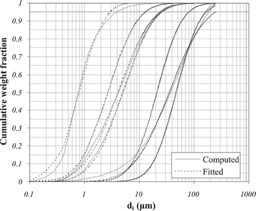
Analytical proof that a lognormal input particle distribution yields lognormal output particle distributions is not available. It is shown however numerically that, whenever the inlet particles have a lognormal size distribution, the outlet particle size distribution, as predicted by the formulations of CitationCalvert (1970) and CitationYung et al. (1978), can be fitted very closely with a lognormal one, . The same is true for dry cyclone separators (CitationEconomopoulou and Economopoulos 2002b).
FIG. 1 Normalized cumulative weight distributions of penetrating particles predicted by the Calvert theoretical model and optimally fitted by lognormal distributions.
The production of micron-sized particles by industrial processes can be characterized by a distribution function describing the particle diameter. In the majority of these processes the size of particles can be fitted satisfactorily through a lognormal distribution function, with parameters the mass median diameter d m , and geometric standard deviation σ g (CitationLicht 1988). This lognormal distribution function has the form:
If the fractional efficiency of the collector for particles belonging to the ith size class is predicted by a formulation of the form Ef i = Ef i (d i ), then the mass fraction of penetrating particles, P i (d i ), belonging to this ith size class is given by the following equation:
In relation to the lognormal distribution of penetrating particles, the fractional penetration P i (d i ) is expressed as follows:
Combination of Equations (Equation22) and (Equation23) yields the following general expression:
Solution Based on the CitationCalvert (1970) Efficiency Formulation
For d i = d p and for d i = d m , Equation (Equation24) takes the form of Equations (Equation25) and (Equation26) that follow:
In order to introduce into Equations (Equation25) and (Equation26) the parameter groups G c d ma and ln σ g that are used in Equation (Equation7) above, we perform the following transformations:
According to Equations [Equation1], [Equation6], and [Equation8], Ef i ] d i = d p = f(G c d pα) and Ef i ] d i = d m = f(G c d mα); also, according to Equation (Equation7), Ef = f(G c d mα, ln σ g ) for any fixed value of Bf. The square root of the ratio C c ] d i = d m /C c ] d i = d p varies very little and approaches unity for typical input particle lognormal distributions. Thus, it has negligible effect on the above equations and can be considered as constant. Based on this analysis, Equations (Equation27) and (Equation28) can be expressed in the following functional form:
The output distribution parameters G c d pα and ln σ p are directly related through Equations [Equation29] and [Equation30] to the input distribution parameters G c d mα and ln σ g and can be uniquely defined for any given set of G c d mα and ln σ g values.
Equations [Equation29] and [Equation30] are amenable to graphical solution, which is provided by the double nomographs in to . Selection of the appropriate figure depends on the value of the dimensionless parameter Bf defined in Equation [Equation2]. In each figure the value of parameter group G c d pα can be read from the abscissa of the upper nomograph and that of ln σ p from the abscissa of the lower one. From these values one can easily calculate the mean diameter d p and the standard deviation σ p of the penetrating dust. For intermediate values of parameter Bf, the output distribution parameters can be calculated through linear interpolation.
FIG. 2 (a) Nomographs based on the Calvert formulation, for Bf = 1.4, yielding the output particle distribution parameters G c d pα and lnσ p as function of the input particle distribution parameters G c d mα and lnσ g . (b) Nomographs based on the Calvert formulation, for Bf = 1.6, yielding the output particle distribution parameters G c d pα and lnσ p as function of the input particle distribution parameters G c d mα and lnσ g . (c) Nomographs based on the Calvert formulation, for Bf = 1.9, yielding the output particle distribution parameters G c d pα and lnσ p as function of the input particle distribution parameters G c d mα and lnσ g . (d) Nomographs based on the Calvert formulation, for Bf = 2.3, yielding the output particle distribution parameters G c d pα and lnσ p as function of the input particle distribution parameters G c d mα and lnσ g . (e) Nomographs based on the Calvert formulation, for Bf = 3, yielding the output particle distribution parameters G c d pα and lnσ p as function of the input particle distribution parameters G c d mα and lnσ g . (f) Nomographs based on the Calvert formulation, for Bf = 4, yielding the output particle distribution parameters G c d pα and lnσ p as function of the input particle distribution parameters G c d mα and lnσ g . (g) Nomographs based on the Calvert formulation, for Bf = 6, yielding the output particle distribution parameters G c d pα and lnσ p as function of the input particle distribution parameters G c d mα and lnσ g . (h) Nomographs based on the Calvert formulation, for Bf = 16, yielding the output particle distribution parameters G c d pα and lnσ p as function of the input particle distribution parameters G c d mα and lnσ g .
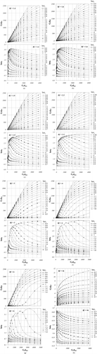
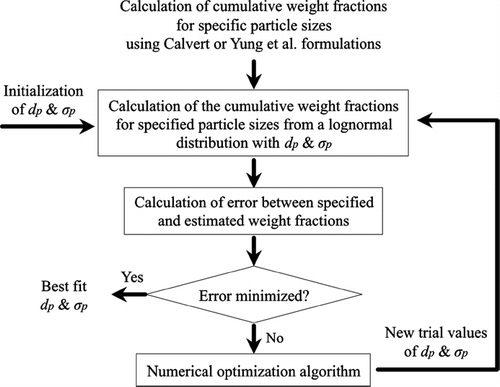
To generate the nomographs in to , the venturi overall efficiency and the cumulative weight fractions of the penetrating particles are computed from the numerical integration of Equation (Equation22) in combination with Equations (Equation1) to (Equation6), over 800 particle diameters and for 750 combinations of G c d mα and lnσ g values. For each such G c d mα and lnσ g combination, the corresponding d p and σ p values are calculated based on an iterative procedure that seeks to minimize the error function, through a numerical optimization algorithm, . To ensure the best possible fitting and obtain smooth isopleths in the generated nomographs, the best-fit procedure for each point is repeated several times with different initial d p and σ p values and the optimum solution is selected.
FIG. 3 Algorithm for generating best-fit lognormal distribution parameters d p and σ p from cumulative weight fraction series computed through the use of Calvert and Yung et al. formulations.
Solution Based on the CitationYung et al. (1978) Efficiency Formulation
The general expression in Equation (Equation24) can take the form of Equations (Equation31) and (Equation32) below, for d i = d m and for d i = d m σ g , respectively:
Solving Equation (Equation31) for ln d m − ln d p /ln σ g , we obtain:
Equation (Equation32) can be rearranged in the following form:
Introducing Equation (Equation33) into Equation (Equation34) and rearranging, we have:
The functional form of Equation (Equation35) is:
Taking into account Equation (Equation36), Equation (Equation34) can be written in the following simple functional form:
To develop the sought graphical solution, we introduce the penetration parameters P = 1 − Ef, P i (d m ) = 1 − Ef i ] d i = d m and P i (d m σ g ) = 1 − Ef i ] d i = d m σ g into Equations (Equation36) and (Equation37), which now take the form:
Moreover, if we introduce Equation (Equation16) into Equation (Equation9) we can express the latter in the functional form of Equation (Equation42), for σ g < 6 (see Part I):
The functional relations (Equation38) to (Equation42) are amenable to graphical solution, which yields the sought parameters d p and σ p of the penetrating dust, for any given set of the input parameters α0.5 B u , G u d mα and lnσ g . More specifically:
| • | In Part I (CitationEconomopoulou and Harrison 2007) the functional relations (40) and (41) are solved graphically, allowing convenient estimation of the overall penetration parameter e 4B u P, for σ g < 6. | ||||
| • | The nomograph in solves graphically the functional relation (42), allowing convenient estimation of the fractional penetration parameters e 4B u P i (d i ), for d i = d m σ g and d i = d m , respectively. | ||||
| • | The double nomograph in solves graphically the functional relations (38) and (39). In that, the abscissas of the upper and lower graphs yield the ratios ln d m /d p /ln σ g and lnσ p /ln σ g . | ||||
| • | From the latter one can easily calculate the output particle size distribution parameters d p and σ p . | ||||
FIG. 4 Nomograph yielding the fractional penetration parameter e 4B u P i (d i ), based on the Yung et al. efficiency formulation, as function of the parameters G u d iα and α0.5 B u.
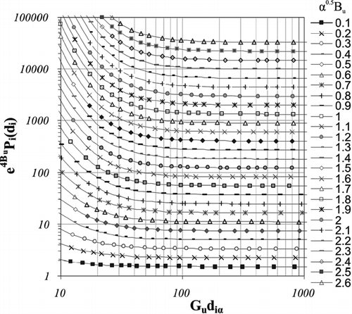
FIG. 5 Nomographs based on the Yung et al. efficiency formulation, yielding the output particle distribution parameters lnd m /d p /d p /ln σ g and ln σ p /ln σ g , as function of parameters P/P i (d m ) and P/P i (d m σ g ).
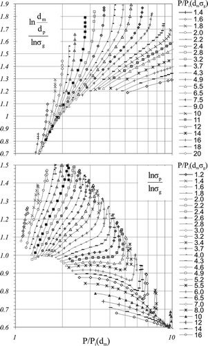
To generate the nomographs in , the venturi overall efficiency and the cumulative weight fractions of the penetrating particles are computed from the numerical integration of Equation (Equation22) in combination with Equations (Equation9) to (Equation13) and (Equation6), over 800 particle diameter increments and 1800 combinations of d m and e 4B u P i (d m σ g ) values. For each such d m and e 4B u P i (d m σ g ) combination, an iterative procedure seeks to find the standard deviation σ g value of the input dust that will yield the specified e 4B u P i (d m σ g ) value. For this estimated standard deviation value σ g , the corresponding output distribution parameters (d p and σ p ) are then estimated, through the same best-fit numerical procedure as the one used for the Calvert model, .
USE OF NOMOGRAPHS
To estimate the lognormal distribution parameters d p and σ p through the use of the graphical models developed, input data are required on the venturi scrubber design configuration (A, L t ), the operating conditions (Q g , T g , P g , Q L , T L ) and the particle properties (ρ p , d m , σ g ). Based on these data, the graphical parameters Bf, G c (for the Calvert model), and B u , α, G u , and e 4B u P(for the Yung et al. model) are estimated, following steps 1 to 3 described in Part I for the overall efficiency estimation. Using the same graphical parameters, d p and σ p are estimated in the next step as follows:
Step 4a. Graphical solution based on Calvert's formulation:
| |||||||||||||||||
Step 4b. Graphical solution based on Yung et al. formulation:
| |||||||||||||||||
EXAMPLE
Estimate the overall efficiency and the size distribution of particles penetrating a venturi scrubber controlling the particle emissions from an industrial boiler firing spent lubricating oils. The flue gas has a flow rate Q g = 5.0 am3/s at T g = 130°C and P g = 1 atm. The particles in the flue gas have a density ρ p = 2500 kg/m3 and their size distribution is lognormal with d mα = 5.05 μ m and σ g = 3.7. The venturi scrubber is a gas-atomized spray type, with liquid introduction at the throat through nozzles at flow rate Q L = 5.5 lt/s. The venturi throat has rectangular geometry of cross-sectional area A = 0.0625 m2 and length L t = 0.80 m.
Solution
Step 1. Calculate gas and liquid physical properties (same as in Part I):
| |||||||||||||||||
Step 2. Calculate model parameters:
| |||||||||||||||||
Step 3a. Graphical parameters based on Calvert's formulation:
| |||||||||||||||||
Step 3b. Graphical parameters based on Yung et al. formulation:
| |||||||||||||||||
Step 4a. Graphical solution based on Calvert's formulation:
| |||||||||||||||||
Step 4b. Graphical solution based on Yung et al. formulation:
| |||||||||||||||||
SUMMARY AND CONCLUSIONS
In view of the newly introduced PM2.5 and/or PM10 air quality standards, the emission inventories are now being refined to account for specific particle sizes (e.g., PM1.0, PM2.5, and PM10). This creates an urgent need for credible predictions of the size-specific particle emissions from each significant source, taking into account the collection efficiencies of the control systems that may exist.
In line with the above requirements, this article presents graphical models for estimating the size distribution of particles penetrating venturi scrubbers. These can be combined with the graphical models of Part I (CitationEconomopoulou and Harrison 2007) for the overall venturi efficiency, so as to enable fast and credible estimates of the size-specific emissions from sources that are controlled by venturi scrubbers (CitationEconomopoulou and Economopoulos 2001). All graphical solutions are rigorous, subject to the assumption of lognormal size distribution of inlet particles.
The graphical solutions are based on two alternative, well-established, theoretical formulations, these of CitationCalvert (1970) and CitationYung et al. (1978). The use of the former is recommended in applications where the empirical parameter f is known or can be experimentally determined. The use of the latter is not restricted as its formulation does not involve any empirical application-dependent parameter. The graphical solution of the Yung et al. formulation is most accurate in cases where σ g < 6.0. This limitation is not very restrictive as venturi scrubbers are used mainly to control sources with fine particle emissions.
When the inlet particles have a lognormal size distribution, the size distribution of the outlet particles, as predicted by the formulations of CitationCalvert (1970) and CitationYung et al. (1978), can be fitted very closely by a lognormal one. This makes possible to define the output particle size distribution through its mass median diameter and standard deviation. The graphical solutions allow easy calculation of these parameters as function of the venturi design and operating conditions.
The use of the graphical models is demonstrated in an application example, in which the output particle size distribution parameters predicted by the formulations of Calvert (d p = 0.461 μ m and σ p = 3.085) and Yung et al. (d p = 0.387 μ m and σ p = 2.742) differ to some degree. Based on the former, one can easily find that the cumulative weight fraction of penetrating particles with diameter less than 2.5 μ m is 93.4%, and based on the latter 96.8% (CitationEconomopoulou and Economopoulos 2001). This divergence is attributed to the differences in the fractional efficiency predictions between the formulations of CitationCalvert (1970) and CitationYung et al. (1978), which is most apparent in the fine particle diameter region.
Acknowledgments
Alexia A. Economopoulou is a recipient of the C. N. Davies Award, a research scholarship from the UK Aerosol Society.
REFERENCES
- Calvert , S. 1970 . Venturi and Other Atomising Scrubbers Efficiency and Pressure Drop . AICHE Journal , 16 : 392 – 396 .
- Calvert , S. 1977 . Air Pollution, , 3rd ed. , Edited by: Stern , A. Vol. IV , New York : Academic Press . Chap. 6
- Calvert , S. and Englund , H. M. 1984 . Handbook of Air Pollution Technology , New York : Wiley-Interscience .
- Davies , C. N. 1945 . Definitive Equations for the Fluid Resistance of Spheres . Proc. Phys. Soc. , 57 : 259 – 270 .
- Economopoulou , A. A. and Economopoulos , A. P. 2001 . Method for Estimating Size-Specific Particulate Emission Inventories . J. Environmental Engineering, ASCE , 127 : 1139 – 1148 .
- Economopoulou , A. A. and Economopoulos , A. P. 2002a . Rapid Performance Evaluation and Optimal Sizing of Dry Cyclone Separators . J. Environmental Engineering, ASCE , 128 : 275 – 285 .
- Economopoulou , A. A. and Economopoulos , A. P. 2002b . Size Distribution of Particles Penetrating Dry Cyclone Separators . J. Environmental Engineering, ASCE , 128 : 919 – 928 .
- Economopoulou , A. A. and Harrison , R. M. 2007 . Graphical Analysis of the Performance of Venturi Scrubbers for Particle Abatement. Part I: Rapid Collection Efficiency Evaluation . Aerosol Sciecne and Technology , 41 : 51 – 62 .
- Goel , K. C. and Hollands , K. G. T. 1977 . Optimum Design of Venturi Scrubbers . Atmos. Environ. , 11 : 837 – 845 .
- Hollands , K. G. T. and Goel , K. C. 1975 . A General Method for Predicting Pressure Loss in Venturi Scrubbers . Ind. Eng. Chem. Fund. , 14 : 16 – 22 .
- Ingebo , R. D. and Foster , H. H. 1957 . Drop Size Distribution for Cross Current Breakup of Liquid Jets in Air Streams NACA Technical Report 4807
- Johnstone , H. F. , Field , R. B. and Tassler , M. C. 1954 . Gas Absorption and Aerosol Collection in a Venturi Atomizer . Industrial and Engineering Chemistry , 41 : 1601 – 1608 .
- Licht , W. 1988 . Air Pollution Control Engineering , New York and Basel : Marcel Dekker, Inc. .
- Nukiyama , S. and Tanasawa , Y. 1939 . Experiments on the Atomisation of Liquids in an Airstream . Trans. Soc. Mech. Eng. (Japan) , 5 : 68 – 75 .
- Placek , T. D. and Peters , L. K. 1981 . Analysis of the Particulate Removal in Venturi Scrubbers—Effect of Operating Variables on Performance . AIChE Journal , 27 : 984 – 993 .
- Raabe , O. G. 1976 . Aerosol Aerodynamic Size Conventions for Inertial Sampler Calibration . Air Pollution Control Assoc. J. , 26 : 856 – 860 .
- Rudnick , S. N. , Koehler , J. L. M. , Martin , K. P. , Leith , D. and Cooper , D. W. 1986 . Particle Collection Efficiency in a Venturi Scrubber: Comparison of Experiments with Theory . Environ. Sci. Technol. Res. , 20 : 237 – 242 .
- Yung , S. C. , Calvert , S. , Barbarika , H. F. and Sparks , L. E. 1978 . Venturi Scrubber Performance Model . Environ. Sci. Technol. , 12 : 456 – 459 .
- Yung , S. C. , Calvert , S. and Barbarika , H. F. 1977 . Venturi Scrubber Performance Model EPA Rep. No. 600/2-77-172