Abstract
This study investigated the dispersion characteristics of polydispersed droplets in a general hospital ward equipped with ceiling-mixing type ventilation system. Injections of water test droplets containing non-volatile content were produced. The injections simulate human coughs with a similar droplet size distribution (peak size at 12 μ m) and airflow rate (0.4 L/s). The dispersion of test droplets was measured in-situ by interferometric Mie imaging (IMI) method combined with an aerosol spectrometer. A multiphase numerical model was employed to simulate the droplet dispersion tracks to provide additional transient position tracking data. Results show that the small size group of droplets or droplet nuclei (initial size ≤45 μ m) behaved airborne transmittable as some nuclei stayed airborne for more than 360 s. The dispersions were strongly affected by the ventilation airflow pattern. The expiratory droplets exhibited a two-stage lateral dispersion behavior, in which rapid dispersion was found in the early “initial dispersion” stage and then the dispersion became much slower in the subsequent “stable” stage. The exhaust air vents significantly enhanced lateral dispersions towards their direction. Droplets in the large size group (initial size = 87.5 μ m and 137.5 μ m) were subjected to heavy gravitational effect and stayed airborne for less than 30 s. Results indicate that the location of exhaust air vents has significant impact on the dispersion pattern of expiratory droplets. It should be carefully considered in designing ventilation systems for health-care settings.
NOMENCLATURE
| c | = |
molar diffusion constant of water vapor [m/s] |
| C 1ϵ, C 2ϵ, C μ | = |
RNG k−ϵ model constants |
| C c | = |
Cunningham correction factor |
| C L | = |
integral time-scale constant |
| C s | = |
molar concentration of water vapor at droplet surface [gmol/m3] |
| C ∞ | = |
molar concentration of water vapor in the carrier phase [gmol/m3] |
| D ii | = |
overall dispersion coefficient of droplets or droplet nuclei [cm2/s] |
| D m | = |
binary diffusion coefficient of water vapor in the carrier phase [cm2/s] |
| D p | = |
droplet or droplet nuclei diameter [μ m] |
| g | = |
gravitational acceleration [m/s2] |
| H | = |
heat transfer coefficient between the two phases [W/m2K] |
| k | = |
turbulence kinetic energy per unit mass [m2/s2] |
| L E | = |
Eulerian integral length scale [mm] |
| L e | = |
Eddy length scale [mm] |
| m | = |
mass fraction of water vapor in the carrier phase |
| n | = |
molar diffusion of water vapor [gmol/m2] |
| Re p | = |
Reynolds number of the droplets or droplet nuclei, Re p = [ρ D p |u−u p |]/μ |
| R E (Δ x) | = |
Eulerian spatial correlation coefficient |
| Sc | = |
Schmit number, Sc = μ /ρ D m |
| t | = |
time [s] |
| T | = |
air temperature [K] |
| T E | = |
Eulerian time scale [s] |
| T e | = |
Eddy lifetime [s] |
| T L | = |
Lagrangian time scale [s] |
| u | = |
instantaneous velocity of the air [m/s] |
| u′ | = |
fluctuation part of instantaneous velocity [m/s] |
| u p | = |
instantaneous velocity of droplets or droplet nuclei [m/s] |
| y* | = |
wall unit, y* = ρ C μ 1/4 k 1/2y/μ |
| = |
Greek Symbols | |
| ϵ | = |
viscous dissipation rate [m2/s3] |
| μ | = |
molecular viscosity of air [g/ms] |
| ρ | = |
density of air [g/m3] |
| ρ p | = |
density of droplets or droplet nuclei [g/m3] |
| τcross | = |
eddy crossing time [s] |
| ζ | = |
a random number with Gaussian distribution |
| = |
Subscript | |
| i | = |
Cartesian coordinate, 1, 2, 3 = x, y, z, respectively |
INTRODUCTION
High number of hospital-acquired infections and large-scale outbreaks of infectious diseases in health care settings indicate that nosocomial infection can be a serious public health problem worldwide. In 2003, the large-scale nosocomial outbreak of severe acute respiratory syndrome (SARS) in Hong Kong had again revealed the seriousness of the issue (CitationLee et al. 2003).
Among various routes of transmission the significance of airborne transmission in nosocomial infections remains skeptical in the medical society, as suggested by CitationBeggs (2003). The skepticisms come from the lack of knowledge in how airborne microorganisms are dispersed in air and mis-understandings in their viability in air. CitationRoy and Milton (2004) also pointed out that the difficulties in detecting the contaminated air leads to the lack of clear proof for airborne transmission. Infectious pathogens can be aerosolized by many human activities and medical procedures, in which human expiratory action is one of the most commonly encountered. In some current nosocomial infection control guidelines “Droplet” and “Airborne” are identified as the two major transmission modes of airborne diseases (e.g., CitationCenters for Disease Control and Prevention 2003). It is classified that pathogen carriers of the “Droplet” mode are droplets of > 5 μm and potential exposure is limited within 3 feet from the source. The “Droplet” mode is considered as a route of direct contact spread, which does not require special attentions in airflow controls in the guidelines. In contrast, pathogen carriers of the “Airborne” mode are droplet nuclei of 1–5 μ m. The term “droplet nuclei” refers to the dried residues of expiratory droplets, which was introduced by CitationWells (1934). The term has been widely adopted in epidemiology studies and medical documents ever since. It is different from the “condensation nuclei” that is commonly used in aerosol sciences in terms of size and formation mechanisms. Considering the possible medical implication of the current study, “droplet nuclei” is used hereinafter following the definition by CitationWells (1934). Diseases identified as “Airborne” transmittable, such as tuberculosis (TB), require air isolation. Such classification remains questionable by physical scientists and engineers as reviewed by CitationBeggs (2003). Some droplets of > 5 μ m in size had evaporation time scales much shorter than their settling time scales, making them become droplet nuclei before getting settled. This largely ignored fact makes the 5-μ m classification between droplet and droplet nuclei very ambiguous.
In modern healthcare settings where mechanical ventilation is usually provided, the ventilation system can play a significant role in airborne transmission. In particular, the dilution effect of the ventilation system has been the major concern. There are guidelines and standards to specify minimum ventilation dilution recommendations for airborne infection control in different healthcare settings (e.g., CitationCenters for Disease Control and Prevention 1994 and CitationThe American Institute of Architects 2001). In considering the effect of dilution, perfectly mixed assumption is usually applied. However, CitationNazaroff et al. (1998) indicated that instantaneous and complete mixing of airborne pathogens in an indoor zone, which the perfectly mixed condition represents, can hardly be achieved in practical situations. Such assumption could lead to substantial underestimation of exposure intensity and predictive capability for infection risk under non-completely mixed dispersion patterns was required.
In contrast to dilution, relatively little research has been done on the dispersion effect of ventilation systems on airborne transmission. It could be attributed to the difficulties associated with such research. CitationChao and Wan (2006) indicated that methods employed in some previous studies, such as visualization methods or using continuum phase surrogates, have different deficiencies in capturing the dispersion characteristics of the polydispersed, evaporating expiratory droplets. CitationChao and Wan (2006) employed polydispersed test droplets and a multiphase numerical method to investigate the dispersion mechanism of expiratory droplets in a clean room environment. Droplet dispersions induced by bulk air movement and turbulent diffusion were compared in their study. However, their results may not be immediately applicable to practical health-care settings since the room geometry and ventilation flow pattern was highly idealized. The air change rate in their experimental clean room (138 hr− 1) was also much higher than that found in health-care settings.
In current infection control practices, the shortage of this knowledge is compromised by isolating infector patients with suspected/confirmed airborne transmittable diseases in single air isolation rooms with very high ventilation dilution rates and controlled pressurization (CitationCenters for Disease Control and Prevention 2003). However, disease transmission from patients with unsuspected cases remains possible, as indicated by the nosocomial outbreak of SARS in a hospital in Hong Kong (CitationRoy and Milton 2004). It indicates that comprehensive review of current nosocomial infection control practices is needed, which requires better fundamental understanding of the dispersion dynamics of expiratory droplets especially in the unprotected areas, e.g., general wards. In this study, size-resolved dispersion characteristics of expiratory droplets in a hospital ward environment with typical ceiling-mixing type mechanical ventilation were investigated. Polydispersed, evaporating test droplets with non-volatile content were used to simulate the expiratory droplets. A multiphase numerical model, similar to that employed in CitationChao and Wan (2006), was to simulate the motion tracks of the expiratory droplets under the inference of the ventilation airflow field. The results were compared with experimental measurements in a real hospital ward.
METHODOLOGY
The Ward Geometry
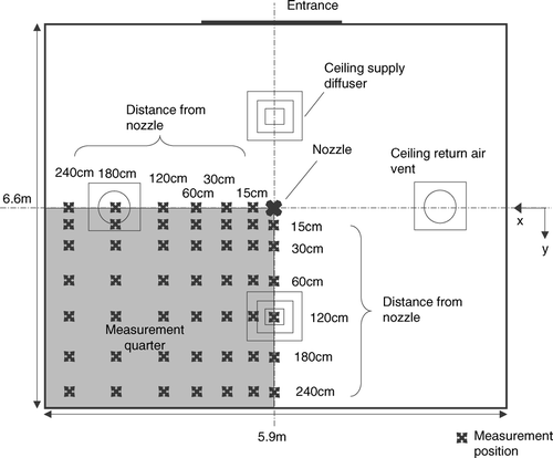
Dispersion dynamics of expiratory droplets were investigated in an experimental ward located in a hospital in Hong Kong. The experimental ward had dimensions of 5.9 × 6.6 × 2.35 m (W × L × H). The ward was equipped with a typical ceiling-mixing type ventilation system with a total supply airflow rate of 1060 m3/hr (11.6 ACH). Conditioned air was supplied from two 4-way spread type ceiling diffusers (0.6 m × 0.6 m) and returned through two ceiling extraction vents (0.6 m × 0.6 m). The air was conditioned by an individual constant volume air-handling unit with electronic temperature controllers located in a plant room outside the ward. A schematic diagram of the experimental ward is shown in . A computational geometry identical to a quarter of the experimental ward was created using GAMBIT (version 2.0; Fluent Inc., 2004) preprocessor. A droplet injection point was created at the center of the ward and 0.8 m above the floor, which was about the same height of the mouth of a patient lying in a bed. The test droplets were injected vertically upward. A total of about 1.5 million meshed elements were created which was composed primarily of hexahedral elements. In constructing the computational meshes, the minimum mesh size of 10 mm near the ceiling supply vent and a maximum mesh size of 120 mm were set. The large meshes were usually at free areas outside the supply air jets. These mesh sizes were determined by referring to the length scales obtained from the PIV measurements and will be described in a later section. Wall unit adaptation was applied to wall-adjacent cells to ensure the wall y values were ≤ 20. The governing equations of fluid and droplet motions, which will be described in the following sections, were solved using a finite-volume based code Fluent (Version 6.2; Fluent Inc., 2005) with second order upwind solution scheme for the carrier phase. Pressure and velocity coupling was solved using the SIMPLE algorithm. The quality of the meshing was examined by performing a set of carrier phase simulation using the boundary conditions listed in with a slightly finer grid size resulting in 2.2 million total meshed elements. The velocity magnitude obtained in two different grid sizes differed by less that 1 × 10− 4 m/s, less than 1 × 10− 5 m2/s2 for turbulent kinetic energy (TKE) and less than 1 × 10− 5 m2/s3 for TKE dissipation rate. Such test gave certain confidence of using the original 1.5-million meshing but it was not a strict grid independence test due to limitations in computational power.
FIG. 1 Schematic diagram of the experimental ward and the IMI measurement setup.
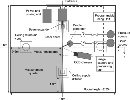
TABLE 1 Boundary conditions and parameter inputs for the numerical simulations
Numerical Approach
The Eulerian-Lagrangian multiphase model had two separate sets of formulations for the carrier phase (air) and the discrete phase (droplets and droplet nuclei). Details about the formulations of the numerical model were described in CitationChao and Wan (2006) and only a brief description will be given here. The behavior of the carrier phase was simulated by solving the Eulerian mass, momentum and energy conservation equations. Turbulence closure of the carrier phase was achieved by the Reynolds Averaged Navier-Stokes (RANS) approach using the renormalization group (RNG) k−ϵ turbulence model. In employing this model, it was assumed that the flow in the computational geometry was fully turbulent and the turbulence was isotropic throughout the room. Standard logarithmic law wall functions were applied at solid boundaries. The turbulence model constants were (C μ, C 1ϵ, C 2ϵ) = (0.0845, 1.42, 1.68). Water vapor transport in the carrier phase was formulated by the species convection-diffusion equation.
The Lagrangian force balance equation describing the motion of the expiratory droplets was:
Local instantaneous velocities of the carrier phase were needed to solve the equations of motion in Equation (Equation1). To construct a fluctuating velocity field from the averaged information the stochastic approach was adopted. In this approach, the fluctuating velocities of the carrier phase were assumed to have a Gaussian probability density function with a variance of 2k/3. Along the trajectory of a particle, the fluctuating component of the local carrier phase instantaneous velocity was generated by u′ = ζ ![]() . ζ was randomly sampled from the Gaussian pdf. Each droplet was allowed to interact with an eddy over a time interval that was the minimum between two time scales: the characteristic lifetime of the eddy or the time that the droplet moved across the eddy. When that time scale was reached, a new ζ would be sampled to generate a new instantaneous velocity. The eddy lifetime in homogeneous and isotropic turbulences can be estimated by T
e
= 2T
L
(CitationGraham and James 1996).
. ζ was randomly sampled from the Gaussian pdf. Each droplet was allowed to interact with an eddy over a time interval that was the minimum between two time scales: the characteristic lifetime of the eddy or the time that the droplet moved across the eddy. When that time scale was reached, a new ζ would be sampled to generate a new instantaneous velocity. The eddy lifetime in homogeneous and isotropic turbulences can be estimated by T
e
= 2T
L
(CitationGraham and James 1996).
The Lagrangian integral time scale of the carrier phase was calculated by:
Boundary Conditions
Boundary conditions and other inputs of the simulations are shown in . The initial droplet size distribution of the injection was adopted from the coughing size distribution reported in literatures. As reviewed by CitationNicas et al. (2005), there are three major studies about the size distribution of expiratory droplets available in the literature. CitationPapineni and Rosenthal (1997) employed optical particle counters (OPCs) and transmission electron microscope analysis, which covered the size range of only 0.3–8 μ m. CitationDuguid (1946) and CitationLouden and Roberts (1967) employed a stain-mark-counting approach, which covered a droplet size range (from 1 to over 1000 μ m) much wider than that reported by CitationPapineni and Rosenthal (1997). The data reported by CitationPapineni and Rosenthal (1997) may also suffer from sampling and transmission losses in the OPCs, as indicated by CitationNicas et al. (2005). Comparing with a bioaerosols study, CitationNicas et al. (2005) judged that the size distributions of CitationDuguid (1946) and CitationLoudon and Roberts (1967) were consistent with the study findings but inconsistent with CitationPapineni and Rosenthal (1997). CitationDuguid (1946) further adjusted the evaporation losses and reported the initial droplet size distributions of sneezing, coughing and talking actions. Since the current study intended to track the fate of expiratory droplets starting from the moment that they were produced, CitationDuguid's (1946) data was adopted for such purpose. However, this decision dose not imply that CitationDuguid's (1946) data resembles the true coughing size distribution more closely than the others since there is still no benchmark expiratory source profile data available in the literature, as reviewed by CitationNicas et al. (2005). Since some size bins had only a few to a few tens of droplets, the number of droplets introduced into the numerical domain were 10 times of that reported in CitationDuguid (1946). The purpose of such production was to ensure that there was enough number of droplets or droplet nuclei for subsequent statistical analysis in each size bin. Non-volatile fraction of the droplets was set at 6% by volume. The compositions of test droplets will be explained later when the experimental set up was described. The supply airflow rate was 0.4 L/s, which was approximately equivalent to exhaling a tidal volume of a normal human lung in each injection. The injection size distribution used in the numerical simulations and the corresponding size distribution of droplet nuclei are listed in . The number concentrations in the table were calculated by assuming there was 0.4 L of air per injection. Each injected droplet was designated with an identification number in the simulation for subsequent motion tracking. With the smallest injection droplet size of 1.5 μ m, the corresponding smallest droplet nuclei size was 0.59 μ m. The relaxation time of such nuclei was τ p ,0.59≈ 2 × 10− 6 s, which was then used as the integration time step for solving the droplet trajectory equations.
TABLE 2 Injection droplet size distribution used in the numerical simulations
A “trap” discrete phase boundary condition was set at all solid surfaces. It implied that the calculation of discrete phase trajectory would be terminated whenever a droplet or droplet nucleus reached a solid surface. Re-suspension was ignored. Corrections for anisotropy of turbulence at boundary layers were also not employed. Some studies showed that the anisotropy of turbulence at boundary layers can greatly affect the calculation of particle deposition (such as CitationMatida et al. (2003) in respiratory track flows and CitationWang and James (1999) in channel flows). In a study conducted in a ventilated room, CitationZhao et al. (2004) employed a discrete phase boundary layer treatment similar to the current study to simulate particle depositions. They compared the numerically predicted and the experimentally measured average particle concentrations in a two-zone model room. The simulated average particle concentration and its decay trend over a 27-minute period matched fairly well with the experimental results. As inferred from CitationZhao et al. (2004), the simplified discrete-phase boundary treatment employed in the current study may provide fair accuracy in predicting particle depositions in ventilated rooms. However, such effect should be investigated and quantified further in boundary layer flows of ventilated rooms.
Experimental Characterization of the Airflow Field
As described earlier the characteristic turbulence time and length scales were correlated to the mean turbulence quantities, k and ϵ, by some empirical functions in the particle tracking model. To verify whether these numerically calculated turbulent scales could closely resemble the actual turbulence characteristics of the ward airflow, experimental characterization of the airflow were conducted in the experimental ward. A set of PIV measurements was made at different distances from the supply air diffuser along the supply air jet. Another set of measurements was made at different height levels at the center of the room, which were outside the envelopes of the supply air jets. Details about the PIV system (LaVision FlowMaster) are given in CitationChao and Wan (2006). The integral length scale, L E , was directly calculated from the spatial instantaneous velocity information obtained by the PIV method by the following definition (CitationHinze 1975):
FIG. 2 (a) Measured integral length scales at different locations. (b) Measured integral time scales at different locations.
In the numerical simulations, a set of integral length scales at the same locations can be calculated using the numerically obtained k and ϵ values by combining Equation (Equation3) and the definition by CitationLu (1995), which becomes L E = 2.27C L k 3/2/ϵ. A best fitted C L value was obtained by comparing the numerically obtained L E and the measured L E values at all PIV measurement positions until the least-square differences from all these locations was obtained. The C L value determined by this method was 0.158 and it was used in the particle tracking simulations. The calculated values of L E by using the numerically obtained k and ϵ values and C L = 0.158 were also plotted in (shown as the ‘computed’ curves). Replacing the spatial variable, x, with the temporal variable, t, in Equations (5–6), the Eulerian integral time scales, T E , at these measurement locations were determined by the time-series velocity data. The numerically computed T L using Equation (Equation3) can be correlated to T E by T E = 2.78T L (CitationLu 1995). The measured T E was also plotted with the computed T E using C L = 0.158 in for comparison, which shows reasonable agreement between each other. The airflow measurement results were also used to calculate the turbulence intensities at the ceiling supply/return vents and the supply jet orientations, which were used as boundary conditions for the numerical simulations.
Experimental Measurements of Droplets and Droplet Nuclei Dispersions
Dispersion distances of the water droplets were also measured in order to make comparisons with the numerical results. A self-developed droplet generator consisting of a pneumatic nozzle, gas and liquid supply lines together with pressure and flow rate control systems was utilized to produce injections which simulate human expiratories. Compressed air was used as the gas supply and “simulated saliva” solution was used to feed the liquid supply line. The compressed air and liquid solution were externally mixed at the tip of the nozzle through an air cap, producing a full-cone injection spray with an angle of about 34° (± 17° from the centerline). The solution was prepared by dissolving 12 g of sodium chloride and mixing 76 g of pure glycerin in 1L of distilled water, referring to the mucus content reported in CitationNicas et al. (2005). Such composition resulted in 6% in volume of non-volatile content in each droplet, which finally became droplet nuclei. The nozzle outlet was located at the center of the ward, 0.8 m above the floor. The injection position was the same as that in the computational geometry. The schematic of the droplet generator setup is shown in . Droplet size distribution produced by the droplet generator was characterized by using an optical IMI method. Details about the IMI measurement principle and the IMI system (LaVision SizingMaster IMI) employed in the current study can be found in CitationChao and Wan (2006) and will not be repeated here. The measurement field of 6 × 8 mm was placed at 50 mm above the nozzle outlet. The size distribution was averaged from a set of 100 images taken from 10 injections (10 images/injection of 1 s). To be consistent with the numerical simulations, the pressure and flow rates of the gas and liquid lines were regulated until a size distribution similar to that reported by CitationDuguid (1946) was achieved. The droplet number counts were calculated from the measured size distribution and liquid flow rate in the supply line. The measured size distribution at the nozzle outlet of the droplet generator is plotted in . The size distribution of the generated ‘coughs’ resembled the CitationDuguid's (1946) distribution reasonably well.
FIG. 3 Schematic of the droplet generator setup.
FIG. 4 Droplet size distribution measured at the droplet generator.
The droplet dispersion measurements were performed using the IMI system combined with an aerosol spectrometer (GRIMM model 1.108). The IMI system had a minimum detection limit of 2 μ m. By calculating from 6% of non-volatile content in the “simulated saliva” solution, the IMI system cannot detect droplet nuclei with initial droplet size of less than 5 μ m. The aerosol spectrometer had a minimum detection limit of 0.3 μ m (measurable range: 0.3–20 μ m; classified into 16 channels), which corresponded to 0.8 μ m in the initial droplet size. The lower end size range of 0.8–5 μ m were measured by the aerosol spectrometer. The aerosol spectrometer employed light scattering method to provide real-time aerosol measurement in 1 Hz frequency.
Before each dispersion measurement, background aerosol level in the ward was measured by the aerosol spectrometer for 30 minutes. The sampling inlet of the aerosol spectrometer was placed at the center of the ward, 1.1 m above the floor. The integrated-average of the 30-minute background measurements would be used to estimate the significant of coagulation in later analysis and also would be offset from the aerosol spectrometer results obtained in the dispersion measurements. Estimating from the background aerosol level and the number of droplets in each injection, the significance of coagulation was minor and was neglected in subsequent analysis. In each droplet dispersion measurement the IMI system and the aerosol spectrometer were turned on 10 seconds before the injection. Then the injection was triggered by an electrical timer switch and maintained for 1 s. Measurements were made at a grid of predefined measurement positions, as shown in . At each of the position shown in the figure, measurement points were located at heights of 0.1 m, 0.6 m, 1.1 m, 1.7 m, and 2.2 m. The measurements were maintained for 360 s at each point. Due to evaporation the droplets started to shrink since its introduction. The droplet sizes detected at the measurement points were reduced. The droplet size continued to decrease until the droplet nucleus was formed after which the size would be stabilized. Before the formation of droplet nuclei, the original sizes of the measured droplets were traced back by the time difference between the measurement time and the time when the injection was stopped. Droplet evaporation during their flight time period could be estimated by integrating Equation (Equation2) and assuming the droplets were traveling at terminal velocity throughout the period. The estimated total evaporated mass was added to the measured size of droplet to estimate their original sizes. After the formation of droplet nuclei, the measured size was correlated to the original size using the fixed non-volatile 6% volume ratio. Each measured droplet or droplet nucleus was then grouped to the size bins, which were defined according to the droplet original sizes () for subsequence data processing. The schematic diagram of the IMI measurement setup is shown in . All measurements were conducted in a quarter of the experimental ward, as indicated in . The operator and most of the instruments were located at the opposite quarter to minimize their disruption to the measurement quarter.
FIG. 5 Grid of measurement positions for droplet dispersion experiments.
RESULTS
Removal of Droplets and Droplet Nuclei
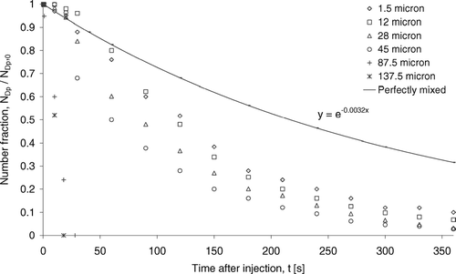
By recording the total number of suspended discrete particles in the numerical domain at a different time, the decay profiles of droplets or droplet nuclei for selected size bins were obtained. The results are shown in . The number fraction is defined as the total number of suspended droplets or droplet nuclei divided by the total number of droplets injected for each particular size bin. The curve marked “Perfectly mixed” was added to indicate the decay of a “gas-like” contaminant perfectly mixed with the room air. The decay constant –0.0032 of the “Perfectly mixed” curve was the air change rate of the room (11.6 hr− 1 = 0.0032 s− 1). The results show that the decay rates of number fraction changed with the initial droplet size, suggesting that the droplets or droplet nuclei removal mechanisms were size-specific. The removal can be characterized by two distinct mechanisms according to sizes. The number fraction of the small size group (initial sizes ≤ 45 μ m) decayed with trends similar to the perfectly mixed gaseous contaminant but the decay rate increased as the initial size increased. It suggests that the small size group behaved airborne transmittable but the influence from gravitation effect became increasingly significant as size increased. The rapid drop in number fraction of the large size group droplets (initial sizes = 87.5 and 137.5 μ m) suggests that their removal was dominated by gravitational settling.
FIG. 6 Decay in number fraction of selected size bins of droplets. Legends indicate initial droplet sizes.
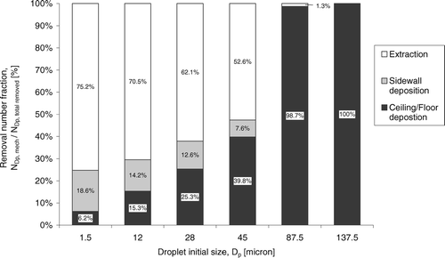
To further understand the results in , the relative importance of three major removal mechanisms is examined by the removal number fraction shown in . The removal number fraction was defined as the number of droplets or droplet nuclei removed by a particular mechanism divided by the total number removed in each size bin. Results were obtained from numerical simulations at the 360th s after the injection. As shown in , more than half of the small size group droplets or droplet nuclei were removed by extraction following the exhaust air stream. However, the removal number fraction by the extraction mechanism dropped from 75.2% to 52.6% as the initial droplet size increased from 1.5 to 45 μ m. It shows that the increase in significance of gravitational and inertial effects with size. The loss in airborne transitivity with size increase is also revealed by the reduction of removal number fraction by sidewall deposition from 18.6% (1.5 μ m) to 7.6% (45 μ m). In the current configuration the expiratory droplets were introduced at the center of the ward. For a particle to deposit on a surface, the particle has to be transported to the boundary layer of that surface by the airflow. The likelihood of the particle to penetrate the boundary layer and finally get deposited on the surface depends on various boundary layer diffusion mechanisms (CitationLai and Nazaroff 2000). The rather simple boundary layer treatment employed in the current model cannot capture this complex phenomenon within the boundary layer in details and further investigations are needed. However, the current result may indicate that the number of particles that could reach the sidewall boundary layers reduced with the increase in size due to the loss of airborne transitivity. As the size increased further, nearly all droplets or droplet nuclei were removed by vertical settling in the large size group showing the dominance of the gravitational effect.
FIG. 7 Removal number fractions for selected size bins of droplets.
Vertical Motions
The removal characteristics shown in and could be further explored by examining the vertical motions of the droplets or droplet nuclei, as revealed in . The curves in the figure are polynomial fits of the numerically predicted mean vertical positions from all airborne droplets or droplet nuclei in each size bin. The experimental mean vertical positions (marked “exp”) are also plotted in symbols in the figure for comparison. The experimental mean vertical positions were obtained by averaging the number of measured droplets and droplet nuclei at all the measurement positions, shown in . Since the results in , both numerical and experimental, were averaged from all droplets or droplet nuclei in each size bin, they do not necessarily represent the behavior of any individual particle but the overall trend of the whole size bin. shows that the two size groups also exhibited two distinct behaviors in vertical motions. The large size group droplets were affected by heavy gravitational effects, which pulled the droplets or the nuclei to settle downward throughout their whole airborne lifetime. Such behavior limited the airborne lifetimes to about 29 s and 18 s for 87.5 μ m and 137.5 μ m droplets, respectively. In contrast, some droplets or droplet nuclei in the small size group remained airborne for more than 360 s, which indicates airborne transmittable behavior. After the initial downward movement, which was induced by the bulk air current these small droplet nuclei were then transported towards the exhaust air vent at the ceiling, as illustrated by the subsequent upward motion. Such vertical motion behavior can be a reason for the high significance of air extraction removal for the small size group. also shows that the numerical and experimental results were in reasonable agreement. It is shown that the numerical model was able to capture the size-resolved motion characteristics of the droplets or droplet nuclei.
FIG. 8 Mean vertical positions of selected size bins of droplets. Legends and indicators are initial droplet sizes.
Lateral Dispersions
, show the lateral mean dispersion distances along the X (towards the exhaust vent) and the Y (transverse to the exhaust vent) directions respectively. Again, the averaged results were used to represent the general trend of the whole size bin, which did not necessarily represent the behavior of any individual droplet or droplet nucleus. The curves were linear fits from numerical results while the symbols are experimental results (marked “exp”). The mean dispersion distances were calculated using the similar method as that in . From the experimental results, it can be seen that the small size group exhibited a two-stage dispersion behavior in both lateral directions. Rather rapid increase in the lateral mean dispersion distances was observed in the early stage of dispersion. After a certain time, the trend became relatively stable. These two stages of dispersion are denoted as the “initial dispersion” stage and the “stable” stage respectively in . Similar patterns were obtained by the numerical predictions. In order to closely represent the numerical data two separate curves were fitted in each size bin. This gave rise to the breaks in the curves in . Reasonable agreement was also found between the numerical and experimental results in these two figures.
FIG. 9 (a) Mean dispersion distances of selected size bins of droplets in X direction. Legends and indicators are initial droplet sizes. (b) Mean dispersion distances of selected size bins of droplets in Y direction. Legends and indicators are initial droplet sizes.
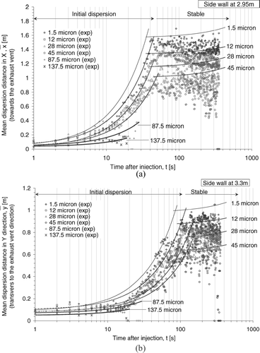
Considering the ventilation configuration in the ward, the initial dispersion stage could mainly be driven by the supply air jets. The 4-way spread type supply air diffusers produced supply air jets in both lateral directions. With the exhaust vents located at the X direction the bulk air streams in the ward eventually flowed towards the exhaust vent, promoting the lateral air movements towards the X direction. Comparing the two figures, the small size group exhibited initial dispersion stage behavior in the first 30–50 s after the injection in the X direction. In the Y direction, the initial dispersion stage behavior lasted until 80–110 s after injection but in slower rates and to shorter distances (about 0.5 m shorter in mean dispersion distances than that in the X direction). It may be because when the droplets or droplet nuclei were driven to the end of the supply jets, the rapid lateral transport ended. Further lateral dispersions were driven by air movements outside of the supply air jets. The rate of lateral dispersion at this stage was much slower showing the “stable” stage behavior.
The results also revealed size dependence in lateral dispersion characteristics. The duration of the initial dispersion stage and the rate of increase in the mean lateral dispersion distance varied with the size of droplets and droplet nuclei. In (the X direction), the numerical results show that the nuclei formed from 1.5 μ m droplets were dispersed to a mean distance of about 1.6 m in the 30-s initial dispersion stage. The mean dispersion distance was reduced to about 1m in the 50-s initial dispersion stage for nuclei formed from 45 μ m droplets. A similar trend could also be observed in the Y direction (). The large size group droplets showed only initial dispersion stage behavior during their presence in the air. Under the heavy gravitational pull, the large size group droplets or droplet nuclei did not suspend in the air long enough to reach the stable stage.
Lateral Overall Dispersion Coefficient
Results from suggest that major lateral dispersions were achieved in the “initial dispersion” stage in which smaller droplets or droplet nuclei dispersed further and in faster rates. Lateral dispersions were also enhanced towards the exhaust vent direction. In order to quantify these effects on lateral dispersions, the dispersion coefficients, D ii , of selected sizes of droplets or droplet nuclei were calculated. Using the numerical position tracking data of the initial dispersion stage, D ii could be calculated by the following expression:
The calculated overall dispersion coefficients in the initial dispersion stage are summarized in . The results show that D ii decreased as droplet size increased. In the X direction, D ii of nuclei formed from 1.5 μ m droplet was about 3.6 times higher than that of the 45 μ m ones. Compared to that of the large size group, D ii of nuclei formed from 1.5 μm droplet was about an order of magnitude higher. The results also show that the enhancement of lateral dispersion towards the exhaust vents was significant. In all size bins shown in , D ii values in the X direction were about 3.0–6.3 times higher than that in the Y direction. The enhancement was more significant in the small size group than in the large size group. As indicated by CitationChao and Wan (2006), lateral bulk air movement is the dominant mechanism in driving the lateral dispersion of expiratory droplets in indoor environments. It can be inferred that the enhancement in bulk airflow towards the ceiling exhaust vents may be a major cause of the large increase in D xx , compared to D yy . The result suggests that the location of the exhaust vent can play a significant role in controlling the dispersion pattern of expiratory droplets. This factor should be carefully considered in the design of ward ventilation configurations.
FIG. 10 Overall dispersion coefficients of selected size bins in the initial dispersion stage.
DISCUSSION
Limitations from the “Empty Room” Simplification
In the current study, a number of practical complexities were not considered. Some previous works such as CitationCheong et al. (2003) showed that furniture significantly disturbs the indoor airflow patterns and also the dispersion of indoor air contaminants by blocking some of the airflows. The presence of real patient/thermal manikin would add another level of complexity by inducing thermal plumes in the room. Studies such as CitationWan and Chao (2005) showed that the thermal plumes could create temperature and also density gradients in the air. They could also significantly affect the contaminant dispersions, as reported by CitationQian et al. (2006). CitationQian et al. (2006) also showed that contaminants injected laterally from the patient had dispersion patterns different from those injected vertically upward. The injection could be affected by the heat plume generated by the real patient/thermal manikin, which implies that the effects of injection orientation should be investigated in conjunction with heat plumes. Although it is shown that these practical complexities have significant impact on the dispersion of contaminants, their relative significances are very difficult to quantify. By taking out all these complexities, the current study was conducted under an “empty room” configuration. Adopting such simplification made the dispersions of droplets or droplet nuclei affected purely from ventilation airflows. The vertical upward injection orientation was selected in the present study such that the lateral dispersions were isolated from the influences of the initial cough jet and was affected by ventilation airflows only. Limitations of the present results in practical applications should be noted.
Importance of Evaporation Kinetics
As reviewed in the introduction section, evaporation is a major feature that should be considered in the study of the fate of expiratory droplets in indoor environments. The results show that the importance of evaporation kinetics varies with different targeted size group of droplets. From , some small size group droplets had dispersion time scales (lifetime) of more than 360 s but the evaporation time scales (i.e., the time needed for shrinking from the initial size to the nuclei size by evaporation) were only in the order of less than 1 s. With such large difference between the two time scales it can be inferred that evaporation plays a relatively minor role on the overall dispersion of small droplets and droplet nuclei. It suggest that the small size group droplets (the major focus of airborne mode transmission) can be considered as dry particles of their nucleus sizes as long as the overall dispersion characteristics in the room is concerned. However, in the large size group the dispersion (around 20–30 s) and the evaporation (in the order of 10 s) time scales are comparable to each other. Evaporation may take place in a major portion of their lifetime. It becomes particularly important when droplet mode transmission is concerned. In the current study, the percentage of non-volatile content was assumed constant for all droplets so that the final nucleus size was directly proportional to the initial droplet size. Actual infectious pathogens were not involved. However, the presence of infectious pathogens could significantly alter the non-volatile content, especially for those pathogens with sizes comparable to the expiratory droplets (e.g., bacterial cells). The loading of microorganisms becomes an additional parameter in the dispersion of expiratory droplets. Further investigations are needed in the biological aspect before applying the current results to infection risk analysis.
CONCLUSIONS
Dispersion characteristics of droplets and droplet nuclei were investigated numerically and experimentally in a general hospital ward equipped with typical ceiling-mixing type ventilation system. Test droplets were introduced with non-volatile content and a size distribution aiming to simulate human expiratories. It is shown that the dispersion characteristics were size-specific and were highly affected by the ventilation airflow pattern. Several specific remarks can be drawn:
| • | Two distinctive dispersion behaviors were observed according to the droplet initial size. The small size group (initial size ≤ 45 μ m) exhibited airborne transmittable behavior. The large size group (initial size = 87.5 and 137.5 μ m) did not stay in the air long enough for airborne transmission due to heavy influence from gravitational settling. Some droplet nuclei in the small size group remained airborne for more than 360 s while the large size group droplets suspended in air for less than 30 s. | ||||
| • | The small size group exhibited a two-stage lateral dispersion behavior with rapid dispersion in the initial dispersion stage and much slower dispersion in the later stable stage. The laterally projected supply air jets could be a major reason for the initial dispersion stage behavior. The large size group droplets or droplet nuclei had only initial dispersion stage behavior due to rapid settling. | ||||
| • | Extraction by following the exhaust air stream was the major removal mechanism (over 50%) for the small size group and gravitational settling was the dominant removal mechanism (over 98%) for the large size group. Considering the large number fraction of the small size group (over 90%) in human expiratories, air extraction can play a significant role in controlling the level of expiratory droplets, especially the airborne transmittable ones. | ||||
| • | The overall dispersion coefficients were enhanced by 3–6.3 times towards the exhaust vents compare to the transverse direction. The enhancement effect was more significant in the small size group than in the large size group. It indicates that the location of exhaust vents has a significant influence on the dispersion pattern of expiratory droplets. | ||||
Acknowledgments
This research is financially supported by the Research Fund for the Control of Infectious Diseases by the Hong Kong SAR Government through Project No. 02040012 (HKUST No: CIDHHS03/04.EG01).
Notes
*Assumption: 0.4L of air per cough, the droplets were evenly distributed in the cough air.
**Assumption: 6% vol. of non-volatile content.
Related Research Data
REFERENCES
- The American Institute of Architects . 2001 . Guidelines for Design and Construction of Hospital and Health Care Facilities , Washington, D.C : The American Institute of Architects Press .
- Beggs , C. B. 2003 . The Airborne Transmission of Infection in Hospital Buildings: Fact or Fiction? . Indoor Built Environ. , 12 : 9 – 18 .
- Beggs , C. B. , Noakes , C. J. , Sleigh , P. A. , Fletcher , L. A. and Siddiqi , K. 2003 . The Transmission of Tuberculosis in Confined Spaces: An Analytical Review of Alternative Epidemiological Models . Int. J. Tuberc. Lung Dis. , 7 ( 11 ) : 1015 – 1026 .
- Centers for Disease Control and Prevention . 1994 . Guidelines for Preventing the Transmission of Mycobacterium Tuberculosis in Health-care Facilities , Atlanta, GA : Centers for Disease Control and Prevention . MMWR 1994;43 (No. RR-13)
- Centers for Disease Control and Prevention . 2003 . Guidelines for Environmental Infection Control in Health-care Facilities , Atlanta, GA : Centers for Disease Control and Prevention .
- Chao , C. Y. H. and Wan , M. P. 2006 . A Study of the Dispersion of Expiratory Aerosols in Uni-directional Downward and Ceiling-return Type Airflows using Multiphase Approach . Indoor Air. , 16 ( 4 ) : 296 – 312 .
- Cheong , K. W. D. , Djunaedy , E. , Poh , T. K. , Tham , K. W. , Sekhar , N. H. , Wong , M. B. and Ullah , M. B. 2003 . Measurements and Computations of Contaminant's Distribution in an Office Environment . Build. Environ. , 38 : 135 – 145 .
- Duguid , J. P. 1946 . The Size and the Duration of Air-Carriage of Respiratory Droplets and Droplet-Nuclei . J. Hyg. , 44 : 471 – 479 .
- Ferron , G. A. and Soderholm , S. C. 1990 . Estimation of the Times for Evaporation of Pure Water Droplets and for Stabilization of Salt Solution Particles . J. Aerosol Sci. , 44 : 415 – 429 .
- Fluent . 2004 . GAMBIT 2.2 User's Guide , Lebanon : Fluent Inc .
- Fluent . 2005 . Fluent 6.2 User's Guide , Lebanon : Fluent Inc .
- Friedlander , S. K. 2000 . Smoke, Dust, and Haze , Oxford : Oxford University Press .
- Graham , D. I. and James , P. W. 1996 . Turbulent Dispersion of Particles using Eddy Interaction Models . Int. J. Multiph. Flow , 22 ( 1 ) : 157 – 175 .
- Hinze , J. O. 1975 . Turbulence , New York : McGraw-Hill, Inc. .
- Lai , A. C. K. and Nazaroff , W. W. 2000 . Modeling Indoor Particle Deposition from Turbulent Flow onto Smooth Surfaces . J. Aerosol Sci. , 31 ( 4 ) : 463 – 476 .
- Lee , N. , Hui , D. , Wu , A. , Chan , P. , Cameron , P. , Joynt , G. M. , Ahuja , A. , Yung , M. Y. , Leung , C. B. , To , K. F. , Lui , S. F. , Szeto , C. C. , Chung , S. and Sung , J. J. 2003 . A Major Outbreak of Severe Acute Respiratory Syndrome in Hong Kong . N. Engl. J. Med. , 348 : 1986 – 1994 .
- Loudon , R. G. and Roberts , R. M. 1967 . Droplet Expulsion from the Respiratory Tract . Am. Rev. Resp. Dis. , 95 : 435 – 442 .
- Lu , Q. Q. 1995 . An Approach to Modeling Particle Motion in Turbulent Flows—I. Homogeneous, Isotropic Turbulence . Atmos. Environ. , 29 ( 3 ) : 423 – 436 .
- Matida , E. A. , DeHaan , W. H. , Finlay , W. H. and Lange , C. F. 2003 . Simulation of Particle Deposition in an Idealized Mouth with Different Small Diameter Inlets . Aerosol Sci. Tech. , 37 : 924 – 932 .
- Morawska , L. 2006 . Droplet Fate in Indoor Environments, or Can We Prevent the Spread of Infection? . Indoor Air , doi:10.1111/j.1600-0668.2006.00432.x
- Nazaroff , W. W. , Nicas , M. and Miller , S. L. 1998 . Framework for Evaluating Measures to Control Nosocomial Tuberculosis Transmission . Indoor Air , 8 : 205 – 218 .
- Nicas , M. , Nazaroff , W. W. and Hubbard , A. 2005 . Toward Understanding the Risk of Secondary Airborne Infection: Emission of Respirable Pathogens . J. Occup. Environ. Hyg. , 2 : 143 – 154 .
- Papineni , R. S. and Rosenthal , F. S. 1997 . The Size Distribution of Droplets in the Exhaled Breath of Healthy Human Subject . J. Aerosol Med. , 10 ( 2 ) : 105 – 116 .
- Qian , H. , Li , Y. , Nielsen , P. V. , Hyldgaard , C. E. , Wong , T. W. and Chwang , A. T. Y. 2006 . Dispersion of Exhaled Droplet Nuclei in a Two-bed Hospital Ward with Three Different Ventilation Systems . Indoor Air. , 16 : 111 – 128 .
- Ranz , W. E. and Marshall , W. R. Jr. 1952 . Evaporation from Drops, Part I . Chem. Eng. Prog. , 48 ( 3 ) : 141 – 146 .
- Roy , C. J. and Milton , D. K. 2004 . Airborne Transmission of Communicable Infection—The Elusive Pathway . N. Engl. J. Med. , 350 ( 17 ) : 1710 – 1712 .
- Wan , M. P. and Chao , C. Y. H. 2005 . Numerical and Experimental Study of Velocity and Temperature Characteristics in a Ventilated Enclosure with Underfloor Ventilation Systems . Indoor Air , 15 : 342 – 335 .
- Wang , B. , Zhang , A. , Sun , J. L. , Liu , H. , Hu , J. and Xu , L. X. 2005 . Study of SARS Transmission Via Liquid Droplets in Air . J. Biomech. Eng. , 127 : 32 – 38 .
- Wang , Y. and James , P. W. 1999 . On the Effect of Anisotropy on the Turbulent Dispersion and Deposition of Small Particles . Int. J. Multiph. Flow , 25 : 551 – 558 .
- Wells , W. F. 1934 . On Air-borne Infection. Study II. Droplets and Droplet Nuclei . Am. J. Hyg. , 20 : 611 – 618 .
- Xie , X. and Li , Y. 2006 . “ How Far Respiratory Droplets Move in Indoor Environments? ” . In Proceedings of Healthy Buildings 2006 Edited by: Fernandes , E. O. , Silva , M. G. and Pinto , J. R. Vol. II , 309 – 314 . Lisbon
- Zhao , B. , Zhang , Y. , Li , X. , Yang , X. and Huang , D. 2004 . Comparison of Indoor Aerosol Particle Concentration and Deposition in Different Ventilated Rooms by Numerical Method . Build. Environ. , 39 : 1 – 8 .