Abstract
A thermophoretic sampler is designed for the collection of particles smaller than 10 nm. The sampler is composed of heated and cooled surfaces separated by a gap of 0.1 mm; a bypass flow is introduced in the design to minimize the diffusional loss of nanoparticles in the upstream flow channel. Particles may be directly deposited on a 3 mm diameter TEM grid for chemical analysis or on other substrates for other purposes. Calculations show that at an inlet flow rate of 1.5 lpm and thermal gradient of 5 × 10⁵ K/m, a maximum collection efficiency of 41% can be achieved for a particle diameter of 1 nm. Ag particles with median size of 6 nm are used to characterize the thermophoretic sampler collection efficiency. The TEM images show that a sizeable number of particles less than 10 nm in diameter are collected, although they are not uniformly distributed on the grid, and the collection efficiency deduced from these deposited particles is much less than the theoretical estimation. Despite this, the efficiency is orders of magnitude higher than previous designs and it is easier to build.
1. INTRODUCTION
Atmospheric aerosols play a role in the global climate through their influence on the Earth's radiation budget. The scattering of solar radiation by aerosols depends on the ambient particle number concentration and particle composition, which are influenced by the rate and prevalence of new particle formation. Nucleation is an important source of atmospheric particles in a variety of conditions. Once new particles form, they can grow quickly to participate in a number of important atmospheric processes such as heterogeneous chemistry, cloud formation, precipitation and the scattering and absorption of solar radiation. Characterizing compounds in the nuclei is important for understanding the mechanisms of nucleation. In addition, knowledge of the composition of atmospheric nano-particles may aid in the assessment of their environmental effects.
Measurement of aerosol chemical composition can be categorized as either off-line or real-time. Few instruments are capable of measuring chemical composition of ultrafine particles in real-time. CitationSmith et al. (2005) reported the first direct, near real-time measurement of chemical composition of particles from 5 to 20 nm in diameter with Thermal Desorption Chemical Ionization Mass Spectrometer (TDCIMS). Off-line measurements of particle composition typically involve the chemical analysis of deposited particles in a laboratory some time after sample collection. Sampling time varies from several hours in urban areas to a day or more under clean background conditions. Filters and impactor stages are most commonly used in off-line measurements. The deposits collected on filter substrates or impactor stages can be analyzed by X-ray fluorescence (XRF), proton induced x-ray emission (PIXE), inductively coupled plasma mass spectroscopy (ICP-MS) or a range of other techniques. Nucleation produces new particles approximately 1 nm in diameter; particles of D p < 10 nm size range are 109 times less massive than those in the micrometer range yielding far less analyte for chemical analysis. Particles collected by filters or impactor stages are typically larger than tens of nanometer; even with sparsely deposited nanoparticles, their low mass concentration poses difficulty for the abovementioned analysis methods. Precipitation mechanisms have also been utilized to sample aerosol particles; diffusion, electrostatic precipitation, and thermophoresis are viable for nanoparticles. Since particle diffusivities increase with decreasing size, as particle sizes decrease, the rate at which they deposit on the nearby surfaces increases. However, diffusion is a stochastic phenomenon; a wide range of sizes deposit on the collecting element yet it is difficult to direct the diffusional deposition to a desired surface. Thus, there is no simple relationship between the change in aerosol concentration across a collecting element and particle size. Electrostatic precipitation has high deposition rate at small diameters depending on the charge state of the particle, but the charging efficiency falls off rapidly below 10 nm. CitationMakela et al. (2002) has designed a special electrostatic precipitator with plate-to-plate collector; ultrafine particles are collected on the TEM (Transmission Electron Microscope) grid and analyzed by energy dispersive X-ray (EDX).
Thermophoresis, a physical phenomenon in which particles, subjected to a temperature gradient, move from high-to low-temperature zones and has a theoretical deposition velocity independent of particle diameter below 50 nm. A number of different thermophoretic precipitators have been developed over the years (CitationKethley et al. 1952; CitationWright 1953; CitationTsai and Lu 1995). CitationBang et al. (2003) developed thermophoretic precipitators for scanning transmission electron microscopy analysis of ultrafine particles, which deposited particles directly onto the TEM grid.
Since 2001, we have observed many nucleation events at Bodega Bay, CA (CitationWen et al. 2006). To identify the nucleating compounds, we have modified and improved the thermophoretic precipitator designed by CitationMaynard (1995), and have validated its collection efficiency under laboratory conditions.
2. THERMOPHORETIC DEPOSITION
For particles with Knudsen number K n ≫ 1, once the particles enter a flow channel with a temperature gradient orthogonal to the flow, they will move toward the channel's cold side and eventually deposit. This effect is called thermophoresis. It is the result of gas molecules impinging on the particle from opposite sides with different mean velocities. Theoretical work was conducted by CitationEinstein (1924). The thermophoretic force F th on a small particle of radius r at temperature gradient ∇ T is,
Assume an initially uniform particle distribution across the flow channel with a temperature gradient present between a heating element and a TEM grid. For the sake of simplicity in determining collection efficiency, the heating element unit and circular cooling plate with TEM grid are represented by a rectangle with length L and width w in .
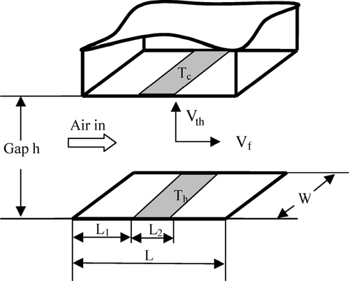
FIG. 1 Schematic of collection region of thermophoretic sampler. L, W and h are the sampler's length, width, and the gap between hot and cold plates. Air inlet flow velocity is V f , the thermophoretic velocity is V th with V th1 and V th2 standing for thermophoretic velocity in the L 1 and L 2 region. T c and T h are cold-and hot-side surface temperatures with T h1 and T h2 standing for the hot side temperature in the L 1 and L 2 region. The temperature gradient in the L 1 and L 2 region are ∇ T 1 = T h1− T c /h and ∇ T 2 = T h2 − T c /h, respectively.
The thermophoresis deposition efficiency can be estimated as,
However, the thermophoretic deposition process is in competition with losses such as diffusion loss along the upstream flow channel and thermophoretic deposition at surfaces other than TEM grid. In the free molecule regime, diffusivity varies as D p − 2, where Dp is the particle diameter, diffusional losses of particles to upstream surfaces increase as particle sizes decreases especially for those smaller than 10 nm. In order to collect particles only on the 3 mm TEM grid, the cold and hot surfaces should be limited to not larger than 3 mm. Yet heat may dissipate to the surrounding area, and generate a temperature gradient (∇ T 1 as shown in ) at places other than collecting surface thereby increasing thermophoretic losses in the upstream channel. This temperature gradient drives the thermophoretic deposition on the surfaces next to the TEM grid. These two particle loss mechanisms can be estimated as follows.
The diffusional loss of nanoparticles for a tube of circular cross section is defined as
The particle loss due to thermophoretic deposition along the upstream flow channel is given as
Following Equation (Equation7), the thermophoretic deposition fraction on the grid can be estimated as
Accounting for diffusion loss (η diff − loss ) and the thermophoretic deposition loss (η th − dep tube ) to the flow channel, the overall particle deposition efficiency to the grid can be expressed as
Assuming diffusional particle loss is minimal, from Equation (Equation10) the optimum volume flow rate and maximum deposition efficiency can be estimated as
3. DESIGN OF THERMOPHORESIS SAMPLER
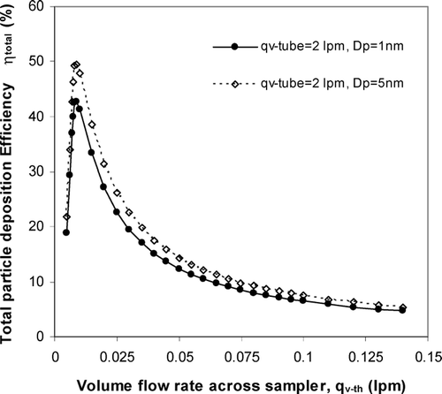
As shown in Equation (Equation9), in order to maximize the total particle collection, one has to maximize the thermophoretic deposition on the grid, and at the same time minimize the diffusion losses to the flow channel. The thermophoretic deposition on the grid is proportional to the temperature gradient between the hot and cold plates, but inversely proportional to the flow rate across the collecting surface. On the contrary, one has to increase the flow rate across the upstream flow channel in order to minimize the diffusion loss. However, simply increasing the carrier gas flow rate (q v − th ) across the sampler will reduce η th − dep grid , as shown in Equation (Equation8). Therefore, we have to design a sampler in a way that maintains a high thermophoretic velocity and a low carrier gas flow rate across the sampler, but this low carrier gas flow rate has to be high enough from inlet to sampler entrance to decrease the diffusion loss. In the thermophoretic precipitator designed by CitationMaynard (1995), the total particle deposition is suppressed because a higher inlet flow rate has to be utilized to minimize the diffusion loss. To improve the collection efficiency, we added a bypass flow channel right before particles entering the temperature gradient region. In this way, a high flow rate (q v − tube ) will be maintained at inlet to reduce diffusion loss, and a relatively low flow rate (q v − th ) can also be achieved at the grid to maximize the thermophoretic deposition. Also, we machined the sampler main body with inlet and outlet from one piece to minimize leaks.
In Maynard's design, the air passes by a channel formed by two circular surfaces, one side is heated and the other side is naturally cooled with a 3 mm TEM grid attached. Since thermophoresis force is proportional to the temperature gradient, a steeper temperature gradient implies greater deposition. We added a thermal electric cooler on the surface supporting the TEM grid to increase the temperature gradient without substantially increasing the hot side temperature, so as to minimize particle volatilization. The gap between the hot and cold plate is about 0.1 mm, and the flow channel width on the collecting surface is maintained at 3 mm, which is the TEM grid diameter. shows the cross section view of thermophoretic sampler. Based on our design of 3 mm (L2) × 3 mm (w) × 0.1 mm (h), and the temperature gradient of 5 × 10⁵ K/m, we estimate that the maximum total deposition efficiency for particle diameter of 1 nm is about 40% at bypass flow rate of 2 lpm and optimum thermophoretic flow rate of 0.01 lpm, as shown in .
FIG. 2 Section view of designed thermophoretic sampler. The gap between the cold and hot side of collection area is 0.1 mm, and a bypass flow channel is introduced to reduce diffusional particle loss.
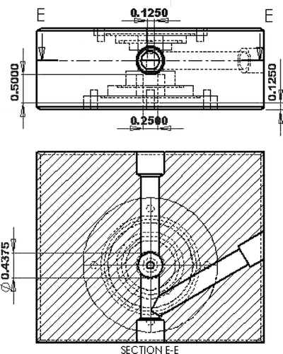
FIG. 3 Theoretical estimation of total particle collection efficiency as a function of thermophoretic flow rate at inlet flow rate, q v − tube , of 2 lpm for particle diameters of 1 and 5 nm.
4. CHARACTERIZATION OF THERMOPHORESIS SAMPLER
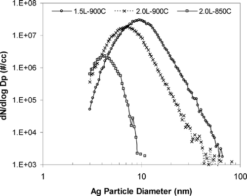
The thermophoretic sampler is evaluated in the laboratory to characterize its nanoparticle collection efficiency. Silver particles are generated with a homogeneous condensation aerosol generator based on the concept described in CitationScheibel and Porstendorfer (1983). The size distributions of lab generated Ag particles at different furnace temperature and flow rate, measured with a SMPS, are shown in .
FIG. 4 Number distributions of Ag particle generated by a homogeneous condensation aerosol generator. The furnace temperature and inlet flow rate are set at 850 and 900°C, and 1.5 and 2 liters, respectively. Note that particle size is shifted to less than 10 nm when furnace temperature is lowered.
The Ag particle generator's temperature is set to 900°C with an inlet flow rate of 2 lpm. Nitrogen is used as carrier gas to prevent any oxidation. The hot side temperature of the thermophoretic sampler is set at 55°C and cold side temperature at 8°C. A holey silicon dioxide coated Ni grid is attached to the center of cold side by magnet. The inlet flow, q v − tube , of 2 lpm is utilized to minimize diffusional loss along the flow channel, and various sampler flow rates, q v − th , are evaluated to estimate the actual collection efficiency. In order to achieve the deposition density of 1 μ m− 2 for TEM analysis, the collecting time can be estimated as
FIG. 5 Ag particles deposited on the transmission electron microscope grid at two different grid locations. The sampling inlet flowrate is 2 lpm, thermophoretic flowrate is 0.015 lpm, temperature gradient is 4.7 × 10⁵ K/m, and the sampling time is 90 minutes.
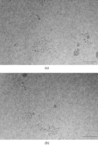
In , on an area of about 0.1 μ m− 2, there are about 90 particles less than 5 nm in diameter giving an estimated deposition density of about 927 #/μ m2, which is far above the deposition density required for TEM analysis. If we project the above deposition density to the whole mesh (about 3511.7 μ m2) of the total 300 meshes, assuming particle deposition is uniform, the number of particles less than 5 nm is estimated to be about 3.3 × 10⁶ on each mesh of the grid base. The thermophoretic sampler collection efficiency can be calculated as
For the application of the thermophoretic sampler in humid environments, water may condense on the cold plate, aggravating later analysis. One potential solution is to use a diffusion dryer upstream to lower the water partial pressure. Likewise, if sampling is to be done in a setting where there are substantial vapor partial pressures, a diffusion denuder will have to be employed to strip these compounds. Care must be taken for both methods to avoid deposition of nanoparticles in the denuder or evaporation of these particles if the vapor contributes to their stability.
5. CONCLUSIONS
A thermophoretic sampler for collecting particles less than 10 nm in diameter directly on a TEM grid has been designed and evaluated with laboratory-generated Ag particles based on the earlier work of Maynard. A bypass flow is added to the collection system to increase the inlet flowrate so that the upstream diffusional loss of nanoparticles onto the flow channel is minimized. A thermoelectric cooler is used to reduce the temperature on the cold side of the thermophoretic sampler, which increases the temperature gradient between the cold and hot sides. Theoretical analysis of nano particle collection efficiency indicates that there exists an optimal volume flow rate through the thermophoretic sampler, at which the maximum collection efficiency can be achieved. The theoretical sampling time for the designed thermophoretic sampler is only 30 minutes at thermophoretic flowrate of 0.015 lpm, ∇ T of 5 × 10⁵ K/m, and particle concentration of 105 cm− 3 for D p < 5 nm. The actual collection efficiency is much less than the theoretical estimate, however, its deposition density is already sufficient for a wide range of off-line analysis techniques.
Related Research Data
REFERENCES
- Bang , J. J. , Trillo , E. A. and Murr , L. E. 2003 . Utilization of Selected Area Electron Diffraction Patterns for Characterization of Air Submicron Particulate Matter Collected by a Thermophoretic Precipitator . J. Air Waste Manag. , 53 : 227 – 236 .
- Einstein , A. 1924 . Theory of Radiometer Energy . Z. Phys. , 27 : 1
- Friedlander , S. K. 2000 . Smoke, dust, and haze—Fundamental of Aerosol Dynamics, , 2nd edition , London : Oxford University Press .
- Kethley , T. W. , Gordon , M. R. and Orr , C. 1952 . A Thermal Precipitator for Aerobacteriology . Science , 116 : 368 – 369 .
- Makela , J. M. , Hoffmann , T. , Holzke , C. , Vakeva , M. , Suni , T. , Mattila , T. , Aalto , P. P. , Tapper , U. , Kauppinen , E. I. and O'Dowd , C. D. 2002 . Biogenic Iodine Emission and Identification of End-Products in Coastal Ultrafine Particles During Nucleation Bursts . J. Geophys. Res. , Vol. 107 : 8110 D19
- Maynard , A. D. 1995 . The Development of a New Thermophoretic Precipitator for Scanning Transmission Electron Microscope Analysis of Ultrafine Aerosol Particles . Aerosol Sci. Technol. , 23 : 521 – 533 .
- Scheibel , H. G. and Porstendorfer , J. 1983 . Ultrafine Particles Adsorbed on HOPG Measured by STM . J. Aerosol Sci. , 14 : 113
- Smith , J. N. , Moore , K. F. , Eisele , F. L. , Voisin , D. , Ghimire , A. K. , Sakurai , H. and McMurry , P. H. 2005 . Chemical Composition of Atmospheric Nanoparticles During Nucleation Events in Atlanta . J. Geophy. Res. , : 110 D22S03, doi:10.1029/2005JD005912
- Tsai , C. J. and Lu , H. C. 1995 . Design and Evaluation of a Plate-to-Plate Thermophoretic Precipitator . Aerosol Sci. Technol. , 22 : 172 – 180 .
- Waldmann , L. 1959 . Advances in Applied Mechanics, Supplement 1: Rarefied Gas Dynamics , Edited by: Talbot , L. 323 London : Academic .
- Wen , J. , Zhao , Y. and Wexler , A. S. 2006 . Marine Particle Nucleation: Observation at Bodega Bay, CA . J. Geophy. Res. , 111 : D8 D08207
- Wright , B. M. 1953 . Gravimetric Thermal Precipitator . Science , 118 : 195