Abstract
A novel Large Particle Inlet (LPI) for accurate sampling of particles larger than 10 μ m (PM > 10 ) over a wide range of wind velocities was designed and evaluated using computational fluid dynamics. The inlet samples air via a narrow circular slit into a funnel-shaped section that turns the sampled flow from a horizontal to vertical direction, facilitating effective post-sampling analysis. The elliptical funnel shape ensures that air drawn through the slit entrance enters omni-directionally and is transported to the vertical section with minimal recirculation. The omni-directional entrance provides a counter-flow effect that aids in turning large particles from the horizontal sample plane to the vertical exit port. The LPI efficiencies are dependent on inlet geometry, particle sizes, sample flowrate, and ambient wind speeds although they are independent of wind direction. At an average wind speed of 2 ms−1, a LPI with a one cm slit entrance width results in sampling efficiencies greater than 27% for particles as large as 100 μ m. The upper cut-size and inlet efficiencies are dependent on the ratio of ambient wind speed and the sample flow velocity at the entrance slit. The aspiration and transport efficiencies as a function of inlet characteristics and ambient wind conditions were determined. This analysis enables optimal inlet design for sampling particles of desired sizes over a broad range of ambient wind conditions.
INTRODUCTION
Particulate Matter (PM) larger than 10 μ m (PM> 10) play an important role in pollutant cycling, especially via mechanisms such as dry deposition and resuspension. Several recent studies have shown that pollutants associated with PM> 10 are responsible for the majority of dry deposition (CitationHolsen et al. 1991; CitationHolsen and Noll 1992; CitationLipiatou et al. 1997; CitationYang et al. 1999; CitationKaupp and McLahlan 1999; CitationYi et al. 2001). For example, the discrepancy between experimental and estimated dry deposition velocities in a recent study of polycyclic aromatic hydrocarbon (PAH) dry deposition (CitationOdabasi et al. 1999) may be due to the presence of large particles (> 10 μ m), which were not considered in the dry deposition velocity estimates by earlier investigators (CitationDoskey and Andren 1981; CitationHoff et al. 1996). This finding is similar to earlier studies that indicated that the contribution of large particles to the dry deposition fluxes of polychlorinated biphenyls (PCBs) and trace metals was important (CitationHolsen et al. 1991; CitationEisenreich 1999; CitationOffenberg and Baker 1999; CitationFranz et al. 1999). CitationLipiatou et al. (1997) also reported that the dry deposition fluxes of PAHs were dominated by large particles (50–90%) in the western Mediterranean Sea. Recently, data collected in the Florida Everglades indicated that dry deposition of Hg bound to PM significantly contributed to the total atmospheric deposition and to the high levels of Hg in runoff (CitationGildemeister 2001). Accurate understanding of deposition, therefore, requires consideration of PM> 10.
Size-segregated large particle sampling is also important for cloud studies. In cloud formation process, size-segregated analysis of activated droplets (typical diameters > 10 μ m) provides critical information about the role of nuclei in droplet formation and precipitation (CitationLovett et al. 1982; CitationCollett et al. 1995). The chemical composition of droplets, which may be the controlling process in acid rain (CitationSeinfeld 1986), is also dependent on droplet size (CitationMunger et al. 1989; CitationCollett et al. 1993 Citation1994). In addition, activated tropospheric ice nuclei that are smaller than ∼ 50 μ m are important for particle growth (CitationChen and Lamb 1999). Physical and chemical characterization studies of activated cloud droplets require accurate sampling and collection of these particles from the atmosphere.
Current efforts to study PM> 10 are hampered by the lack of an effective sampler for large particles. Most particle samplers are focused on sampling particles less than 10 μ m because sampler designs have been largely driven by the environmental community concerned about the role of these particles on human health (CitationJohansson et al. 2007; CitationVerhoeff et al. 1996). There have, however, been a few attempts at designing a sampler for large particles. May [1982 (reprinted)] developed a Swing impactor which captured particles by impaction onto a long slender rectangular arm rotating in free-stream. This impactor was designed to sample/capture particles > 30 μ m in the open air for wind speeds greater than 8 mph. Subsequently, this instrument was extended to form a swing cascade impactor by May in 1942, which eventually became a prototype for the current cascade impactors (CitationMay 1982). The new impactor designs have focused on the collection of smaller particles well into the sub-micron size range, but the size of the largest particles collected is restricted to only 18 μ m (MOUDI, MSP). This upper limit is controlled by the difficulty in sampling large particles from the ambient because of their large inertia.
Here, a design for a new inlet for effective sampling of large particles is presented. The inlet, called the large particle inlet (LPI) was designed using computational fluid dynamics (CFD) modeling. The inlet performance is characterized as a function of varying geometries and operating parameters. The novel LPI can sample particles as large as 100 μ m at wind speeds up to 7 ms− 1 with well-characterized sampling efficiencies.
APPROACH
Inlet Efficiency
There are several established criteria for representative sampling of ambient aerosol (CitationBelyaev and Levin 1974; CitationVincent 1989; CitationHangal and Willeke 1990). In general, it is accepted that isoaxial and isokinetic conditions result in representative sampling of aerosol particles from most environments (CitationGysels and Grieken 1999). It is, however, usually very difficult to satisfy these conditions because of constantly changing wind speeds and wind directions. This difficulty is compounded for large particles because of their significant inertia and gravitational velocity.
Typically inlets sample anisokinetically, which requires that the relationship between inlet efficiency, geometry, and flow parameters be established prior to its deployment. Inlet efficiency is defined as the ratio of the particle concentration delivered to the aerosol measurement section of the sampler to that in the ambient. The net inlet efficiency is dependent on both the aspiration and transmission efficiency. Aspiration efficiency is the ratio of the aspired particle concentration to that present in ambient air. Transmission efficiency is the ratio of the particle concentration transmitted to the sampling section to that aspired into the inlet.
Aspiration efficiency depends strongly on particle inertia which can be characterized by their Stokes number (Stk) given by:
The criteria for representative aerosol sampling have been established using aspiration and transmission efficiencies as a function of Stk, isoaixal, anisoaxial, isokinetic, and anisokinetic conditions (CitationBelyaev and Levin 1974; CitationVincent 1989; CitationHangal and Willeke 1990). In this study, aspiration and transmission efficiencies of LPI were determined as a function of Stk and free stream wind speed (U0).
FLOW MODELING
Deployment of the LPI for large particle measurements requires a prior understanding of the LPI sampling efficiency dependence on inlet geometry and sampling flowrate for varying particle sizes and ambient wind speeds. In addition, interactions between the external and internal flows need to be understood. The commercial computational fluid dynamics (CFD) software, FLUENT (FLUENT Inc., NH; Version 6.1.22) was used to calculate the flow fields in and around a chosen sampler design. FLUENT uses a finite volume technique to solve the mass, momentum, and energy conservation equations. Initial simulations were performed using two-dimensional axisymmetric models and the results from this model were then used to obtain initial conditions for subsequent 3D simulations. The calculations were performed with double precision, standard solution, and the numerical convergence for continuity calculations were ∼ 10−10 for 2D simulations and ∼ 10−6 for 3-D simulations. To further ensure convergence, the simulations were run until velocities at several select locations were unchanged with additional iterations.
The LPI was located in the center of a cylindrical wind tunnel [160 cm diameter (y-z axis), 300 cm long (x-axis)]. The wind velocity direction was assumed to be along the x-axis and the gravity along the y-axis. The boundary conditions for the wind tunnel inlet and outlet were velocity-inlet and outlet-vent, respectively. The wind tunnel walls, LPI inner-curved wall, LPI outer wall, and the top lid were set as stationary wall boundaries. The LPI sampling exit area was set as pressure outlet, with the boundary value adjusted to obtain the required sample flowrate.
For 3D simulations, the complex inlet shapes required the grids to be Tet/Hybrid or TGrid. In addition, Hex element and Cooper methods were also used where applicable. High resolution gridding in regions of large velocity gradients (e.g., near the slot entrance, boundary of inner wall, etc.) was employed. Grid sensitivity was tested by determining the change in velocity field at select locations in the inlet as the grid density was doubled in regions of high velocity gradient. For final simulations with the LPI geometry, the total number of grid cells over the computational domain was ∼ 4 × 10⁶.
Particle trajectories in and around the LPI were calculated using the particle tracking code in FLUENT. To determine inlet efficiency, particles are injected far from the inlet (∼ 50 cm away), where velocities were spatially uniform. Injection points were located equidistantly (0.1 cm spacing) over a rectangular xy-plane of width 26 cm and height 10 cm. This large injection region ensured that the sampled particles were away from the boundaries of the injected area for all test cases. A large number of particles (26,000) were injected to ensure that the sampling efficiency calculation was independent of the injected number.
The typical Reynolds numbers in and around the inlet (∼ 6.7 × 10⁴) suggested turbulent flow; therefore, the k – ε turbulent model was used in the simulations. The sensitivity of the choice of the turbulent model on simulation tests was determined by considering two different turbulent models—the standard k – ε model and the Reynolds Stress Model (RSM). At the Reynolds number of interest, both models should be valid, with the RSM model being more accurate in predicting swirling flow. The RSM is, however, computationally more expensive as it solves an additional system of 7 equations, while the k–ε only requires the solution of two additional equations. Initial calculations with different LPI designs are made using the k – ε turbulence model and a sensitivity analysis was conducted to determine the influence of the choice of turbulence model on the obtained results.
The turbulent eddies in the inlet will influence particle transmission characteristics. For simplicity, however, initial particle trajectory calculations were made using the laminar tracking model. The effect of turbulence on particle calculations was determined by calculating total inlet efficiencies using the particle turbulent tracking code in FLUENT. The influence of the choice of turbulent intensities (5% and 10%) and length scales (1 cm and 3 cm) on the inlet efficiencies was studied.
LPI DESIGN
Horizontal Inlet
CitationHangal and Willeke (1990) established correlations for anisoaxial sampling and calculated aspiration efficiencies based on Stk, the ratio of ambient to inlet velocity, and aspiration angle between the inlet and free stream. Using this correlation, an upward facing inlet (θ = 90°) operating in a wind speed of 3.5 ms−1 will not sample particles larger than 30 μ m (Stk > 0.3). For efficient aspiration of large particles, the inlet must be oriented horizontally (θ = 0) and sample isokinetically (U0/U = 1).
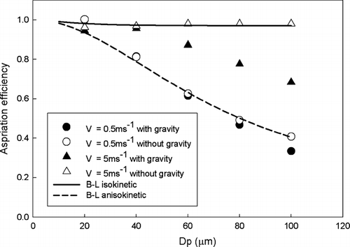
The initial large particle inlet design investigated was a horizontal tube inlet directed into the wind. The effect of gravitational settling on the aspiration efficiency was studied for a sampling velocity of 5 ms−1 and varying wind velocities. As shown in , aspiration efficiency for a wind speed of 5ms− 1 neglecting gravity was the same as that predicted by the correlation of CitationBelyaev and Levin (1974). Considering gravity, however, results in an anisoaxial sampling condition. For example, a particle of 80 μ m diameter with a sedimentation velocity of ∼ 0.19 ms−1 will enter a horizontal inlet at an angle of 2.2° to the horizontal. This anisoaxial effect due to gravitational sedimentation increases as particle size increases. For low wind speeds, however, the aspiration efficiency calculations with and without gravity are both consistent with the predictions of CitationBelyaev and Levin (1974) (U0 = 0.5 ms−1; ). This is because superisokinetic sampling results in higher velocities near the inlet and, hence, reduced gravity and anisoaxial sampling effects. This suggests that superisokinetic conditions could be used to decrease the influence of gravity on aspiration efficiency.
FIG. 1 Aspiration efficiency of horizontal LPI based on particle size and free stream wind speed (U0) and the correlation of CitationBelayaev and Levin (1974) for near isokinetic and anisokinetic sampling conditions.
Misalignment of a horizontal inlet with respect to the mean flow can result in lowered large particle sampling efficiencies, with efficiencies ∼0 for angles > 90° (CitationHangal and Willeke 1990). Typical ambient conditions result in wind velocities and directions that can change over short durations of time. Locating the inlet on a rotating platform can ensure isoaxial flow, but operation of the rotating platform is complicated especially under extreme weather conditions (CitationGysels and Grieken 1999). In addition, isokinetic sampling requires active flow control linked to real-time wind velocities, complicating the instrument and increasing its cost.
An additional complication of a horizontal inlet design is that subsequent particle separation typically requires the flow to be vertical to minimize large particle deposition losses. Particle losses in a 90° turn will be significant and if the inlet is operated at variable velocities to maintain isokinetic sampling, the turning losses will be variable. The particle size information will, therefore, be difficult to extract using a horizontal inlet even with a computer-controlled rotating platform and active flow system.
Novel LPI; Funnel Type (Upward Facing)
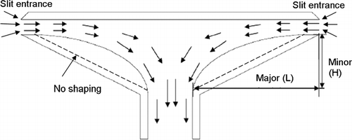
A thin-wall upward facing (vertical) inlet is used in many commercial samplers in part because they do not require rotating parts and are easy to operate. A vertically oriented inlet samples particles from all directions without requiring re-orientation with a change in wind direction. In addition, the sampled particles travel vertically after entering such an inlet, eliminating the need for an additional flow turning section. A simple vertical inlet, however, does not sample large particles (diameter > 30 μ m) efficiently. The LPI design has an omni-directionally open horizontal section to sample flow from the ambient and a vertical section to transport the sample to the analysis/collection section. A general schematic diagram of the LPI is shown in .
Determination of Inner Wall Geometry
LPI Internal Flow
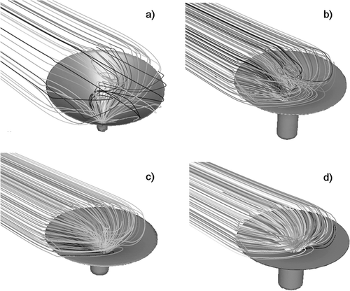
The shape of the funnel-section determines the LPI internal flow and particle sampling characteristics. The air sampled into the LPI needs to turn 90° from the entrance to the exit. For a smooth turn, flow separation and eddy formation inside the inlet must be avoided. In , the top lid was hidden for easy visualization. For an initial design, a flat-shaped funnel inside-wall was examined (). The increase in channel width along the flow direction in the funnel results in large recirculation regions (). To minimize or eliminate these regions the sampler walls were shaped to enable flow expansion without boundary layer separation. Initially, a rounded inner wall (8 cm along both the minor and major axis; ) was considered. Subsequently, elliptical wall shapes with long horizontal and short vertical axes were examined [labeled 8-6 (major axis length 8 cm and minor axis length 6 cm); and 8-4]. The elliptical shaping helps smooth the flow in the funnel section, though for the 8-8 shape, a significant region of recirculation still exists (). For the 8-6 and 8-4 shapes, the flow field was seen to be well developed without significant recirculation regions ( and ).
Counterflow Effect
An advantage of an omni-directional inlet design is that a counterflow effect is created by the flow being sampled from all directions even though large particles only enter the inlet from the upwind direction. This effect is critical to efficiently turn large particles from a horizontal to vertical direction. Effective counterflow requires sufficient pressure drop across the entire circumference of the entrance slit. An examination of the pressure distribution in the xz-plane (parallel to the cover top) at the center of the slit width reveals that the presence of the top lid provides sufficient pressure drop to result in near “axi-symmetric” pressure distribution in the inlet at a moderate wind velocity of 2 ms−1 (). As wind-velocity increases, the counterflow
FIG. 4 Pressure profile around LPI a) at 2 m−s (U0) b) 7 m−s (U0) from top view and 3D reverse path line from exit at c) 2 m−s (U0) d) 7 m−s (U0). Particle trajectory of 100 μ m at e) 2 m−s (U0) and f) 7 m−s (U0).
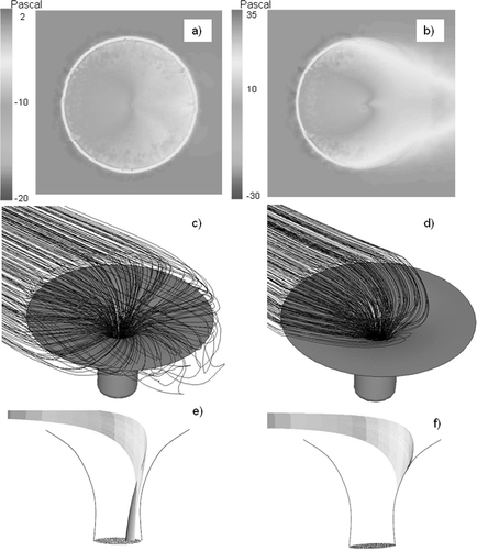
effect diminishes (). The extent of the counterflow effect is determined by the ratio (R) of ambient wind velocity (U0) to the average entrance slit velocity (Uslit). For R < 1, i.e., for low ambient wind velocity or relatively high entrance velocity, the path lines of the sampled flow are seen to enter the inlet omni-directionally (). The lid is hidden in the figure for ease of visualization. When R > 1, the increased pressure differential provided by the wind velocity () results in the majority of the sample flow entering the inlet from the upstream direction diminishing the counterflow effect (). Consequently, for low ambient wind velocities, particles with diameters as large as 100 μ m can be effectively turned 90° because of the counterflow effect (). At higher wind speeds, however, the diminished counterflow effect results in particles being lost on the opposite wall ().
Sampling Flowrate
The inlet aspiration efficiency as a function of sampling flowrate was studied for a wind speed of 5 ms−1 and two particle sizes (30 and 50 μ m). For a low sampling flowrate of 30 LPM [which is consistent with that of existing instruments such as the MOUDI (MSP, MN)], the inlet efficiency was ∼0 for particles larger than 30 μ m. Even for flowrates as large as 300 LPM the inlet efficiency was ∼ 0 for large particles as the small entrance velocities result in little or no counterflow effect (). Effective operation of the LPI requires large sampling flowrates (∼ 1000 to 1400 LPM), consistent with typical high volume air samplers (Tisch, OH). As the pressure drop in the LPI is small, a large flowrate can be obtained with reasonably sized pumps. For sample flowrates of 1000 and 1400 LPM, the LPI can successfully sample large particles. The inlet shaping has a small effect on the aspiration efficiencies, with the 8-6 shape having a slightly higher efficiency than the 8-4 shape ().
TABLE 1 Inlet efficiencies for 30 and 50 μ m diameter particles for the 8-4 and 8-6 LPI designs at different sampling flowrates
The yearly average wind speeds near ground-level at locations such as Potsdam (NY), Albany (NY), Los Angeles (CA), and Gainesville (FL) are in the range of 0.7 to 3.2 ms−1 (weatherunder.com). A LPI sampling flowrate of 1400 LPM results in average inlet slit velocity (Uslit) of 3.5 ms−1. This ensures that the LPI will operate with a counterflow effect for most ambient wind conditions. A large LPI exit diameter (3 cm) was used to minimize the pressure drop in the inlet and permit the use of the same vacuum pump as that deployed with a conventional high volume sampler.
LPI Efficiency
From 3D simulation results, it was determined that 8-4 shape has the best internal air flow patterns (i.e., absence of any recirculation regions) for a wide range of wind speeds at a sampling flowrate of 1400 LPM. For these design conditions (8-4; 1400 LPM sample flowrate; average slit entrance velocity of 3.5 ms− 1), the effect of the operating conditions and inlet dimensions on the performance of LPI was studied.
The aspiration, transmission, and net inlet efficiencies for a slit width of 1 cm were determined for wind speeds ranging from 1 to 7 ms− 1 (). For a selected sampling flow rate, the inlet entrance sampling area (Asample), defined as the subset of the slit entrance region from which airflow enters the LPI, is seen to be dependent on wind velocity. At low wind speeds, the sample flow enters the inlet nearly omni-directionally (), i.e., Asample is almost the same as the area of slit entrance (Aslit). At high wind speeds, because of the dynamic pressure the sample flow enters the inlet primarily from the forward (upstream) direction (). This results in a sampling velocity (Usample) that is greater than the average slit entrance velocity, Uslit. For all ambient wind velocities the simulation results show that the sample velocities are higher than U0, resulting in superisokinetic sampling. Thus, aspiration efficiency, for the range of wind velocities studied (1–7 ms−1) is consistent with superisokinetic sampling, i.e., efficiency decreases with particle size and increases with wind speed ().
FIG. 5 (a) Aspiration efficiency (b) transmission efficiency (c) inlet efficiency for a 1 cm slit width (Q = 1400 LPM) as function of particle diameter at various wind speeds (U0).
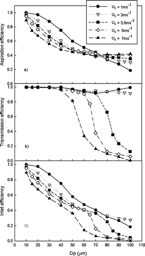
The transmission efficiency is dependent on the ability of the particles to turn 90° towards the vertical exit. For U0 > Uslit, the counterflow effect provided by the omni-directional sample flow results in a transmission of ∼ 100% for particles as large as 100 μ m (). For wind speeds higher than the average entrance velocity, the counterflow effect does not exist and larger particles are lost by impaction on the inner wall (as illustrated in ). The particle size above which impaction losses become important is referred to as the drop-off size. Higher ambient wind speeds result in higher particle inertia, and hence lower particle drop-off size.
The overall inlet efficiency follows a gradual decrease with particle size for wind speeds less than Uslit (1 ms−1 and 2 ms−1 cases). For U0 ≥ Uslit, the inlet efficiencies decrease gradually to a drop-off size, and then drop suddenly due to the transmission loss for larger particles. The LPI design with a 1 cm slit width can sample 50 μ m diameter particles at an overall efficiency of ∼ 36% for a wind speed of 7 ms−1. At low wind speeds, 100 μ m diameter particles can be sampled at an efficiency > 20%. In general, inlet efficiency is limited by aspiration efficiency for smaller particle sizes and transmission efficiency for larger particles.
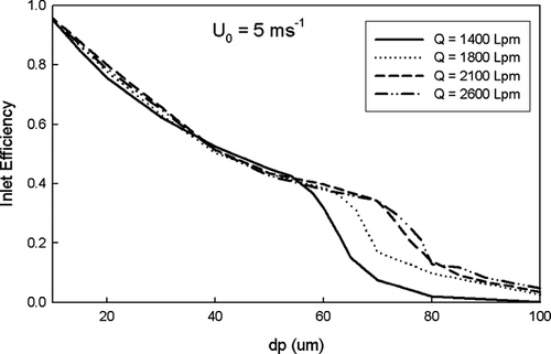
The sampling efficiency of large particles can be increased by increasing the sample flowrates. As shown in , for particles larger than the drop-off size, the inlet efficiency increases due to the improved transmission efficiency with the increased average entrance velocity. For particles smaller than the drop-off size, however, the inlet efficiency is unchanged. This is because, for these sizes, the inlet efficiency is only dependent on the aspiration efficiency which is function of the entrance Stokes number (Equation [1]). The entrance Stokes number is only dependent on the ambient wind speed, and, therefore, the inlet efficiency is independent of the sampling flowrate.
FIG. 6 Inlet efficiencies for different sampling flowrate (Q) for LPI slit width of 1 cm and an ambient wind speed (U0) of 5 m/s.
For comparison with existing large particle inlets, the exponentially tapered inlet of Noone et al. (1992) which is used for cloud studies with a counterflow impactor technique was chosen. This inlet is similar in design to the LPI, without the cover. Based on their analysis, for a particle diameter of 20 μ m and a freestream velocity of 4.9 ms−1, their inlet has a sampling efficiency of 30%. Our analysis suggests that the LPI will have an inlet efficiency of ∼ 80% at a freestream velocity of 5 ms−1 for a 20 μ m diameter particle. The primary difference is the counterflow effect provided by the presence of the cover.
Slit Widths
To determine the role of slit width on the inlet efficiency, three cases were studied: 0.5, 1, and 2 cm. For a selected sample flowrate (1400 LPM), the slit width determines the entrance Stokes number, and, hence the particle aspiration efficiency. The aspiration efficiency increases with the increased slit width. For large slit widths (2 cm), however, slower entrance velocities limit the counterflow effect to low ambient wind speeds. Also, for high ambient wind-speeds, only a fraction of flow entering the large slit width entrance is sampled, while the rest of the flow passes through. A LPI design with a large slit width will, therefore, have low net inlet efficiency at high wind-speeds (). A large slit width design also has strong wind velocity-dependent inlet efficiency. A smaller slit width (0.5 cm) results in higher stokes number and entrance velocity. Hence it operates at a higher superisokinetic condition. While this results in
FIG. 7 Inlet efficiencies for various wind speeds (U0) for LPI slit widths (hs) of 0.5, 1, and 2 cm and a sampling flowrate of 1400 LPM.
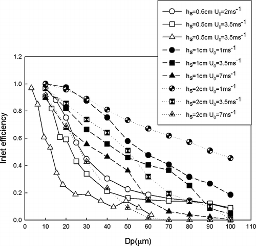
lower net inlet efficiency, its sampling characteristics are less dependent on wind-velocity. For a LPI sampling flowrate of 1400 LPM, a slit width of 1 cm has the best balance between sampling efficiency and wind independence over a wide range of particle sizes.
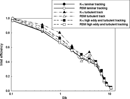
The sensitivity of particle trajectory calculations to the choice of flow models and particle tracking options was studied using two different turbulent models (RSM and standard k-ε) and different freestream turbulence conditions. The effects are quantified based on the changes in inlet efficiencies for varying parameters. In , the total LPI efficiencies calculated using laminar and turbulent models are shown. The efficiencies calculated with both turbulent models were very similar for the range of particle sizes studied. Accounting for the turbulent eddies, results in particle efficiencies that are ∼ 10% different from the values obtained using laminar tracking. The different turbulent intensities and length scales did not significantly alter the inlet efficiency calculation. Based on these tests, we conclude that the use of k-ε turbulent model for flow calculations and laminar particle tracking for LPI inlet efficiency calculations is acceptable.
Empirical Correlation for LPI Inlet Efficiency
Under typical operations, an ambient air sampler will experience a wide range of wind-velocities. To accurately relate the sampled particle concentration to an ambient concentration for the entire range of possible operating conditions, an empirical correlation is required to relate LPI sampling characteristics to operating conditions. In addition, to aid inlet design tailored for a selected size range, a correlation that relates inlet dimensions and operating conditions to its performance is required. The vertical inlet sampling efficiency correlation of CitationVincent (1989) has been used by Noone et al. (1991) to analyze the performance of an omni-directional inlet without the top lid. The CitationVincent (1989) correlation is, however, not seen to accurately predict LPI performance, as it does not account for the effect of the funnel-shape entrance and the inlet cover. Here, we develop an empirical correlation for the LPI design from the simulation results.
The LPI aspiration efficiency curves have a S-shape which can be represented by a 4-parameter equation:
where A asp is aspiration efficiency, A max is asymptotic maximum, A o is minimum aspiration efficiency and Stk is stokes number, Stk 50 is Stokes number corresponding to 50% aspiration efficiency, β is the slope of the S-curve that determines its steepness. To aid curve fitting, A max was assumed to be 1.0. A nonlinear curve-fitting algorithm was used to calculate the parameters, Stk 50, β, and A 0 from the simulation results of A asp as a function of Stk.
A similar approach is used to determine a correlation to relate LPI transmission efficiency to the inlet operating parameters. For the transmission efficiency, the simulation results were used to determine the parameters of the S-curve equation (Equation [2]), assuming A max was 1 and A o was 0, i.e.,
TABLE 2 The parameters for aspiration efficiency correlation determined from the nonlinear curve fitting
TABLE 3 The parameters for transmission efficiency correlation determined by nonlinear curve fitting
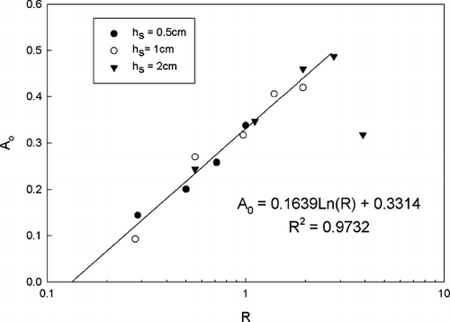
that A0 is strongly dependent on R, the ratio of ambient wind speed (U0) to average entrance velocity (Uslit). From the simulation results (), A0 can be obtained as a function of R as:
To simplify the correlation, an average value of Stk 50 and β was calculated for each slit width design. The final empirical equation for net inlet efficiency for the 1 cm slit width LPI design is:
To ensure that the simplifications used to obtain the inlet efficiency correlations (Equations [2], [3], and [6]) do not affect their accuracy, the correlation predictions were compared with the original simulation results (). The aspiration and transmission efficiency curves are seen to fit the simulation results reasonably. Using the average values for β and Stk 50 based on slit width, the net inlet efficiency correlation accurately predicts efficiencies over the entire range of Stokes numbers of interest (). The correlation curve can, therefore, be used to characterize LPI performance as a function of particle size for the wide range of ambient wind speeds (< 7 ms −1), velocity ratios (R; < 3) and Stokes number (< 45) that are common for ground-level sampling.
FIG. 10 Comparison of empirical predictions and simulation results of (a) aspiration efficiency, (b) transmission efficiency, and (c) inlet efficiency. The slit width for the test cases was 1 cm.
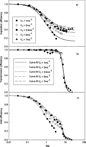
TABLE 4 Maximum and minimum difference (%) between simulation results and predictions of the empirical correlation of inlet efficiency
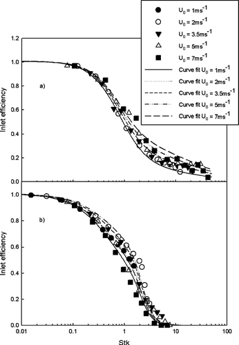
The same procedure was used to determine the correlation parameter values for the 0.5 and 2 cm slit width designs ( and ). The empirical correlation curves for 0.5 and 2 cm slit width cases are compared with the simulation results in . The correlation predictions are within 13% and 20% for 0.5 and 2 cm slit width designs, respectively ().
FIG. 11 A comparison of inlet efficiency predictions with simulation results for slit widths of (a) 2 cm and (b) 0.5 cm.
The obtained correlation curves can be used as a design tool for the development of new LPI designs optimized for the operating conditions of interest or for characterizing a designed LPI.
Validation of LPI Simulation Results
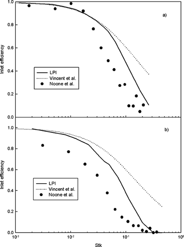
To test predictions of the proposed correlation, the design of Noone et al. (1992) was considered. The Noone et al. (1992) omni-directional inlet (referred to here as the Noone inlet) also has a funnel-shape with and inner wall curved exponentially but without a top lid. The diameter of funnel is 24.5 cm (LPI is 21 cm) and flowrate is ∼ 1414 LPM, similar to the LPI. To validate flow field and particle trajectory calculations, the CFD simulations of the LPI without the top lid were performed and the resultant inlet efficiency curves compared with the experimental results of the Noone inlet. In addition, the experimental results were also compared with the empirical correlation of a thin wall vertical sample probe (CitationBrixey et al. 2005). The correlation of CitationBrixey et al. (2005) was obtained using a foam media at the probe entrance to eliminate the vena contracta effect caused by inertia of the cross wind. The shaped inner wall of the Noone and LPI inlets will also not result in the formation of the vena contracta and hence the correlation of CitationBrixey et al. (2005) is appropriate for comparison here.
The inlet efficiency of the Noone inlet is predicted to decrease with increasing Stokes number (). At small Stokes numbers, the Brixey et al correlation and our simulation results match experimental results closely. At higher Stokes number, the numerical results predict a greater drop in efficiency with increasing Stokes number than that suggested by the Brixley correlation. This is because, with the curved sample probe, particles with large Stokes numbers are lost on the curved wall opposite to the wind direction, and this effect is suppressed in the straight tube correlation with the vena contracta effects reduced. For two freestream velocities studied (4.9 and 8.5 m/s), the predictions of our numerical results match experimental data better than the empirical correlation of Brixley et al. This provides a preliminary validation of the flow and particle trajectory calculation procedure used to obtain the LPI inlet efficiency correlation.
CONCLUSIONS
Analysis of the sampling characteristics of a horizontal inlet suggests that for large particles, gravitational effects are important and not accounted for by the correlation of CitationBelyaev and Levin (1974). The contribution of the gravitational settling velocity results in anisoaxial orientation of large particles, and their effective sampling requires superisokinetic rather than isokinetic sampling. However, a horizontal large particle inlet would be difficult to deploy in typical ground-based sampling applications. For such applications, a novel LPI design is proposed. The LPI is a funnel-shaped vertical inlet with a flat top lid to ensure an omni-directional horizontal sampling plane. An elliptical inner wall shape results in a gradual expansion of the inner volume and hence a smooth turn of the flow and particles to the vertical section of the inlet.
CFD simulations were used to determine inlet efficiencies as a function of the inlet dimensions and operating parameters. The LPI always operates at superisokinetic condition because of the dynamic pressure of the wind. For average slit entrance velocity greater than the freestream velocity, the top lid ensures that the flow is sampled from all directions and this provides a counterflow effect that aids the turning of large particles into the vertical section of the inlet. For a slit width of 1 cm and a flow rate of 1400 LPM, the LPI can sample particles as large as 100 μ m with an efficiency of 27% at low wind speeds (e.g., 2 ms−1) and 50 μ m particles with an efficiency of ∼ 36% at high wind speeds (e.g., 7 ms−1). The CFD simulation results were used to obtain an empirical correlation to relate the inlet sampling efficiency as a function of inlet dimensions, particle size, and operating conditions.
APPENDIX
FLUENT Parameters
The typical parameters used in the flow modeling are listed below:
Models
Solver: Segregated, Implicit, Steady (2D and 3D)
Turbulence: k-ε, Standard formulation, Intensity of 5%, Length scale is same as the slot width (2, 1, 0.5 cm); Intensity of 10% and length scale of 3 cm were used for sensitivity analysis.
For results in , the RSM turbulence model parameters are: Standard formulation 7 equations, Intensity of 5% and 10%, Length scale is 1 and 3 cm.
Particle Calculations
Particle trajectories are calculated using average flow velocities (standard formulation, no turbulent dispersion). Turbulent dispersion was applied for 1cm slot width and wind speed 3.5 ms−1 case to estimate the effect of turbulence on particle trajectories. Turbulent intensity and length scale were also varied to determine the effect of turbulent parameters on inlet efficiencies.
Other Parameters
Fluent defaults were used for all other solver approaches such as Velocity formulation, Gradient option, Under-Relaxation factors, Pressure-velocity coupling, and discretization.
Grid
Tet/Hybrid element and TGrid were mainly used for 3D simulation because of complex geometry of LPI. Hex element and Cooper method were also used when applicable. High resolution in regions of large gradients (e.g., near the slot entrance and boundary of inner wall, etc.) was employed. The simulations were run to convergence, as determined by tracking and ensuring that the flow was unchanged with iterations at different select locations. Sensitivity to grid sizing was tested by ensuring that the flow was largely unchanged by grid refinement. The total grid size was ∼ 4 × 10⁶.
ACKNOWLEDGEMENT
This work was supported by a MRI development grant from the National Science Foundation BES-0521137, Cynthia Ekstein project officer.
References
- Belyaev , S. P. and Levin , L. M. 1974 . Techniques for Collection of Representative Aerosol Samples . J. Aerosol Sci. , 5 : 325 – 338 .
- Brixey , L. A. , Evans , D. E. and Vincent , J. H. 2005 . Aspiration efficiency of a thin walled probe at right angles to the wind . Aerosol. Sci. Technol. , 36 ( 9 ) : 1144 – 1156 .
- Chen , J. P. and Lamb , D. 1999 . Simulation of Cloud Microphysical and Chemical Process Using a Multicomponent Framework: Part II: Microphysical Evolution of a Wintertime Orographic Cloud . J. Atmos. Sci. , 56 : 2293 – 2312 .
- Collett , J. L. Jr. , Iovinelli , R. and Demoz , B. 1995 . A Three Stage Cloud Impactor for Size-Resolved Measurements of Cloud Drop Chemistry . Atmos. Environ. , 29 ( 10 ) : 1145 – 1154 .
- Collett , J. L. Jr. , Bator , A. , Rao , X. and Demoz , B. B. 1994 . Acidity Variations Across the Cloud Drop Size Spectrum and Their Influence on Rates of Atmospheric Sulfate Production . Geophys. Res. Lett. , 21 : 2393 – 2396 .
- Collett , J. L. Jr. , Oberholzer , B. and Staehelin , J. 1993 . Cloud Chemistry at Mt. Rigi Switzerland: Dependence on Drop Size and Relationship to Precipitation Chemistry . Atmos. Environ. , 27A : 22 – 42 .
- Dhaniyala , S. , Flagan , C. R. , McKinney , K. A. and Wennberg , P. O. 2003 . Novel Aerosol/Gas Inlet for Aircraft-Based Measurements . Aerosol Sci. Technol. , 37 : 828 – 840 .
- Doskey , P. V. and Andren , A. W. 1981 . Modeling the Flux of Atmospheric PCBs across the Air/Water Interface . Environ. Sci. Technol. , 15 : 705 – 711 .
- Eisenreich , S. J. 1999 . Increased Atmospheric Deposition of Pops to Aquatic Systems Near Urban Industrial Centers . Epidemiology , 10 ( 4 ) : 502
- Franz , T. P. , Eisenreich , S. J. and Holsen , T. M. 1998 . Dry Deposition of Particulate Polychlorinated Biphenyls and Polycyclic Aromatic Hydrocarbons to Lake Michigan . Envrion. Sci. Technol. , 32(23) : 3681 – 3688 . Dec. 1, 1998.
- Gildemeister , A. E. 2001 . Urban Atmospheric Mercury: The Impact of Local Sources on Deposition and Ambient Concentration in Detroit, MI. , Ph.D. Dissertation, University of Michigan, Ann Arbor, MI
- Gysels , K. and Grieken , R. V. 1999 . Field Evaluation of a Wind Tunnel–Impactor System for Sampling Ambient Aerosols . J. Aerosol Sci. Technol. , 30 ( 5 ) : 639 – 650 .
- Hangal , S. and Willeke , K. 1990 . Aspiration Efficiency: Unified Model for All Forward Sampling Angles . Environ. Sci. Technol. , 24 : 688 – 691 .
- Hoff , R. M. , Strachan , W. M. J. , Sweet , C. W. , Chan , C. H. , Shackleton , M. , Bidleman , T. F. , Brice , K. A. , Burniston , D. A. , Cussion , S. , Gatz , D. F. , Harlin , K. and Schroeder , W. H. 1996 . Atmospheric Deposition of Toxic Chemicals to the Great Lakes: A Review of Data Through 1994 . Atmos. Environ. , 30 : 3505 – 3527 .
- Holsen , T. M. , Noll , K. E. , Liu , S. and Lee , W. J. 1991 . Dry Deposition of Polychlorinated Biphenyls in Urban Areas . Environ. Sci. Technol. , 25 : 1075 – 1081 .
- Holsen , T. M. and Noll , K. E. 1992 . Dry Deposition of Atmospheric Particles: Application of Current Models to Ambient Data . Environ. Sci. Technol. , 26 : 1807 – 1815 .
- Johansson , C. , Norman , M. and Gidhagen , L. 2007 . Spatial and Temporal Variations of PM10 and Particle Number Concentrations in Urban Air . Environ. Monitoring and Assess. , 127 : 477 – 487 .
- Kaupp , H. and McLahlan , M. S. 1999 . Distribution of Polychlorinated Dibenzo–p–Dioxins and Dibenzofurans (PCDD/Fs) and Polycyclic Aromatic Hydrocarbons (PAHs) Within the Full Size Range of Atmospheric Particles . Atmos. Environ. , 34 : 73 – 83 .
- Lipiatou , E. , Tolosa , I. , Simo , R. , Bouloubassi , I. , Dachs , J. , Marti , S. , Sicre , M. A. , Bayona , J. M. , Grimalt , J. O. , Saliot , A. and Albaiges , J. 1997 . Mass Budget and Dynamics of Polycyclic Aromatic Hydrocarbons in the Mediterranean Sea . Deep–Sea Research II , 44 : 881 – 905 .
- Lovett , G. M. , Reiners , W. A. and Olson , R. K. 1982 . Cloud Droplet Deposition in Subalpine Balsam Fir Forests: Hydrological and Chemical Inputs . Science , 218 : 1303 – 1304 .
- May , K. 1982 . A Personal Note on the History of the Cascade Impactor . J. Aerosol Sci. , 13 : 37 – 47 .
- Munger , J. W. , Collett , J. Jr. , Daube , B. Jr. and Hoffmann , M. R. 1989 . Chemical Composition of Coastal Stratus Clouds: Dependence on Droplet Size and Distance from the Coast . Atmos. Environ. , 23 : 2305 – 2320 .
- Noone , K. J. , Charlson , R. J. , Covert , D. S. , Ogren , J. A. and Heintzenberg , J. 1988 . Design and Calibration of a Counterflow Virtual Impactor for Sampling of Atmospheric Fog and Cloud Droplets . Aerosol Sci. Technol. , 8 : 235 – 244 .
- Odabasi , M. , Tasdemir , Y. , Vardar , N. , Sofuoglu , A. and Holsen , T. M. 1999 . Measurement of Dry Deposition and Air-Water Exchange of Polycyclic Aromatic Hydrocarbons with the Water Surface Sampler . Environ. Sci. Technol. , 33 : 426 – 434 .
- Offenberg , J. H. and Baker , J. E. 1999 . Aerosol Size Distributions of Polycyclic Aromatic Hydrocarbons in Urban and Over Water Atmospheres . Environ. Sci. Technol. , 19 : 3324 – 3331 .
- Seinfeld , J. H. 1986 . Atmospheric Chemistry and Physics and Air Pollution , Wiley, New York
- Verhoeff , A. P. , Hoek , G. , Schwartz , J. and van Wijnen , J. H. 1996 . Air Pollution and Daily Mortality in Amsterdam . Epidemiology , 7 : 225 – 230 .
- Vincent , J. H. 1989 . Aerosol sampling: Science and practice , Chichester, UK, Wiley
- Yang , H. H. , Chiang , C. F. , Lee , W. J. , Hwang , K. P. and Wu , E. M. Y. 1999 . Size Distribution and Dry Deposition of Road Dust PAHs . Environ. International , 25 : 585 – 597 .
- Yi , S. , Shahin , U. , Sivadechathep , J. , Sofuoglu , S. C. and Holsen , T. M. 2001 . Overall Elemental Dry Deposition Velocities Measured Around Lake Michigan . Atmos. Environ. , 35 : 1133 – 1140 .
