Abstract
Synthetic fibers with non-circular cross-sections are used in air filters. These fibers may offer performance advantages over traditional fibers with circular cross sections because they have more surface per unit volume of fiber upon which particles can collect. Starting with a solution for the velocity field around fibers with elliptical cross-sections, expressions for predicting the single-fiber efficiency for particle collection by the interception mechanism were developed for elliptical fibers. The interception efficiency predictions depend on filter solidity, fiber properties such as size, aspect ratio, and orientation of the cross section relative to the incoming flow, and particle diameter. The expressions demonstrate that single fiber interception efficiency for elliptical fibers generally increases with increasing particle diameter, increasing solidity, increasing aspect ratio, and as the major axis of the ellipse becomes more perpendicular to the incoming air flow.
LIST OF SYMBOLS
| a | = |
distance between the foci of elliptical fiber cross-section |
| A | = |
factor in Equation (Equation7) from CitationRaynor (2002) |
| B | = |
factor in Equation (Equation7) from CitationRaynor (2002) |
| C | = |
factor in Equation (Equation7) from CitationRaynor (2002) |
| df | = |
circular fiber cross-section diameter |
| dp | = |
particle diameter |
| D | = |
factor in Equation (Equation7) from CitationRaynor (2002) |
| E | = |
factor in Equation (Equation7) from CitationRaynor (2002) |
| F | = |
factor in Equation (Equation7) from CitationRaynor (2002) |
| G | = |
factor in Equation (Equation7) from CitationRaynor (2002) |
| H | = |
factor in Equation (Equation7) from CitationRaynor (2002) |
| Kn | = |
Knudsen number |
| Ku | = |
Kuwabara number |
| lf | = |
length of major axis of elliptical fiber cross-section |
| L | = |
filter thickness |
| n | = |
number of iterations |
| NR | = |
non-dimensional particle diameter for circular fibers |
| R* | = |
particle diameter for elliptical fibers |
| wf | = |
length of minor axis of elliptical fiber cross-section |
| x | = |
x-coordinate in Cartesian coordinate syste |
| xf | = |
x-coordinate of point on fiber surface |
| xp | = |
x-coordinate of point on line normal to fiber surface |
| Xp | = |
non-dimensional x-coordinate of point on line normal to fiber surface |
| Xr | = |
dimensionless distance for calculating efficiency at Δ θ = 90° |
| y | = |
y-coordinate in Cartesian coordinate system |
| yc | = |
distance from centerline that limiting streamline enters domain for circular fiber |
| yf | = |
y-coordinate of point on fiber surface |
| yp | = |
y-coordinate of point on line normal to fiber surface |
| y0 | = |
distance from centerline that limiting streamline enters domain for elliptical fiber with Δ θ = 0° |
| y45 | = |
distance from centerline that limiting streamline enters domain for elliptical fiber with Δ θ = 45° |
| y90 | = |
distance from centerline that limiting streamline enters domain for elliptical fiber with Δ θ = 90° |
| Yp | = |
non-dimensional y-coordinate of point on line normal to fiber surface |
| Z | = |
parameter defined in Equation (Equation22) to ease computations |
| α | = |
filter solidity |
| δ | = |
modified non-dimensional particle diameter for elliptical fibers |
| Δ θ | = |
orientation angle |
| ϵ | = |
aspect ratio |
| ηD | = |
single-fiber diffusion efficiency for fibers with circular cross-sections |
| ηF | = |
single-fiber efficiency for fibers with circular cross-sections |
| ηI | = |
single-fiber impaction efficiency for fibers with circular cross-sections |
| ηR | = |
single fiber interception efficiency for fibers with circular cross-sections |
| ηR,E | = |
single fiber interception efficiency for fibers with elliptical cross-sections |
| ηR,E(90°) | = |
single fiber interception efficiency for fibers with elliptical cross-sections at Δ θ = 90° |
| ηT | = |
total filter efficiency |
| φ | = |
φ-coordinate in elliptical coordinate system |
| φf | = |
φ-coordinate of point on fiber surface |
| φp | = |
φ-coordinate of point on line normal to fiber surface |
| χ | = |
chi;-coordinate in elliptical coordinate system |
| χc | = |
chi; -coordinate of outer boundary of solution domain |
| χf | = |
chi; -coordinate of fiber surface |
| χp | = |
chi; -coordinate of point on line normal to fiber surface |
| Ψ* | = |
non-dimensional stream function |
| Ω | = |
ratio of the interception efficiency at Δ θ = 0° to the interception efficiency at Δ θ = 90° |
INTRODUCTION
Among the most common control methods for reducing exposure to airborne particles are fibrous filters, sheets or pads of small fibers oriented randomly primarily in the two dimensions perpendicular to the air flow passing through the filter. Two parameters are most important for defining the performance of fibrous filters: efficiency and pressure drop. Efficiency, the fraction of particles entering a filter that are collected, is influenced strongly by particle diameter. Pressure drop, a function of the drag force imparted to the air by the stationary fibers, influences the energy required to move air through the filter. Filters made using technologies that allow them to function at a lower pressure drop for the same efficiency or with a higher efficiency for the same pressure drop are considered to have better performance for most applications.
A method for predicting filter efficiency is to use “single fiber theory.” For fibers with circular cross sections, the total efficiency for a filter, ηT, can be related to the efficiency of a single fiber, ηF, by the equation
Interception efficiency is the theoretical collection efficiency by a fiber for spherical particles under the assumption that the particles have size but neither inertia relative to the flow nor the ability to diffuse so that they follow air streamlines around the fiber. If the center of a particle passes within one particle radius of the surface of a fiber, it is considered to be collected by the fiber. As indicated in , there will be a limiting streamline on which a particle following the streamline will barely be able to touch a fiber at a single point. For fibers with circular cross sections, particles on the limiting streamline are captured at the point along the fiber surface that is 90° from the front of the fiber. Single fiber efficiency is defined for circular fibers as the number of particles collected by a fiber divided by the number of particles whose centers would pass through the volume occupied by the fiber if it were not there, assuming the incoming particle concentration is uniform. Thus, referring to , single fiber interception efficiency is yc, the distance from the centerline that the limiting streamline enters the solution domain, divided by the fiber radius, df/2.
FIG. 1 Illustration of particle interception by a circular cross-section fiber with radius df/2. A particle follows the limiting streamline shown until it contacts the fiber at an angle of 90° relative to the incoming flow. The distance from the centerline to the point that the limiting streamline enters the solution domain, yc, divided by df/2 is the single fiber interception efficiency in this case.
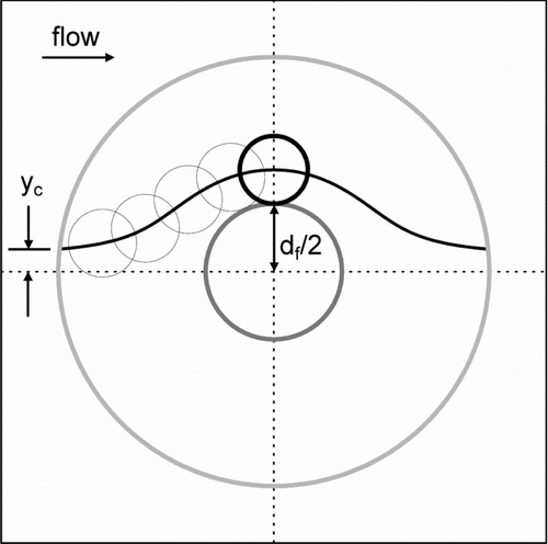
With these definitions, the stream function presented by CitationKuwabara (1959) can be used to calculate the interception efficiency for a circular fiber as
With the increasing sophistication of polymer fiber production, making filters from fibers with non-circular cross-sectional shapes may be an alternative for achieving substantial improvements to filter performance. Fibers with elliptical, lobed, and wedge-shaped cross sections are available (CitationHutten 2007). These non-circular fibers may improve overall filter efficiency by offering a larger surface upon which particles can deposit per unit volume of fiber. However, limited data exist on the potential effectiveness of fibers with non-circular cross-sections. Some authors have utilized analytical and numerical procedures to predict velocity fields and drag for flow around fibers with square or rectangular cross-sections (CitationBrown 1984; CitationFardi and Liu 1992a, Citation1992b; CitationWang 1996; CitationOuyang and Liu 1998; CitationAdamiak 1999; CitationZhu et al. 2000). Most of these papers are complex computationally, limiting their utility for real filter problems. In addition, only CitationFardi and Liu (1992b) provided expressions that are useful for predicting filtration efficiency.
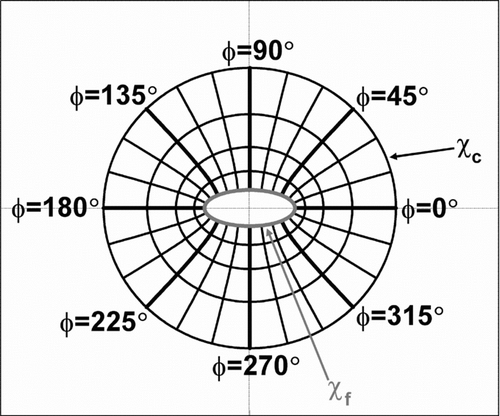
Using methods employed by CitationKuwabara (1959) for fibers perpendicular to incoming air flows, CitationRaynor (2002) solved flow fields around fibers with elliptical cross-sections. As illustrated in , he utilized an elliptical coordinate system (χ,φ) which is related to Cartesian coordinates (x,y) by the expressions
FIG. 2 Diagram of solution domain having a solidity of 0.04 for a fiber with an elliptical cross-section having an aspect ratio of 2.5. The elliptical coordinate system is superimposed on the solution domain. Curves of constant χ are ellipses whereas curves of constant φ are hyperbolas. The surface of the fiber and the outer boundary of the solution domain are indicated as having values of χf and χc, respectively.
THEORY DEVELOPMENT AND METHODS
Development of an Analytical Expression for Δ θ = 90°
Interception efficiency for single fibers with elliptical cross-sections, ηR,E, will depend on ϵ, Δ θ, α, and the non-dimensional particle radius, R*, which can be defined as
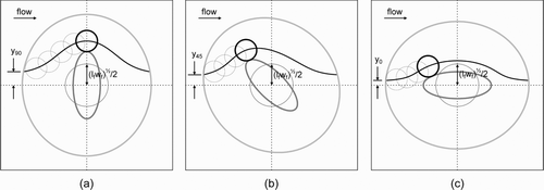
FIG. 3 Illustration of particle interception by elliptical cross-section fibers with the major axis of their cross-sections oriented at (a) 90°, (b) 45°, and (c) 0° to the incoming flow. A circle with radius (lfwf).5ex1−.1em/−.15em.25ex2/2, which has an area equal to the area of the elliptical cross-section, is superimposed on each figure. The particle follows the limiting streamline shown until it contacts the fiber. The starting point of the limiting streamline and the position on the cross-section where the particle contacts the fiber vary with the angle of orientation. The distance from the centerline that the limiting streamline enters the solution domain—y90, y45, or y0—divided by (lfwf).5ex 1−.1em/−.15em.25ex 2/2 is the single fiber interception efficiency in these cases.
As mentioned previously, single fiber efficiency for a fiber with a circular cross-section is defined as the number of particles collected by the fiber divided by the number of particles whose centers would pass through the volume occupied by the fiber if it were not there. For fibers with elliptical cross-sections, however, the number of particles that would pass through the volume occupied by a fiber will vary with ϵ and Δ θ even if the cross-sectional area of the fiber is constant. To provide a consistent basis for comparing single fiber efficiency across fibers having different cross-sectional shapes and orientations, single fiber efficiency for fibers with non-circular cross-sections will be defined as the number of particles collected by the fiber divided by the number of particles that would pass through the volume occupied by a fiber with a circular cross-section of the same area as the original fiber's cross-section if the fibers were not there.
Using Equation (Equation7) for Δ θ = 90°, the value of the stream function of the limiting streamline that passes R* from the surface of the fiber at φ = 0 can be calculated. Then, referring to , single fiber interception efficiency for elliptical fibers with Δ θ = 90° is calculated as y90, the distance from the centerline that the limiting streamline enters the solution domain, divided by (lfwf).5ex1−.1em/−.15em.25ex2/2, the radius of a fiber with a circular cross-section that has the same area as the cross-section of the elliptical fiber. The result for the interception efficiency at Δ θ = 90° is
Development of an Empirical Expression for Δ θ ≠ 90°
As shown in and , the value of φ at which a particle will pass closest to the fiber surface for Δ θ = 45° and 0° is not obvious as it is for a circular fiber or an elliptical fiber at Δ θ = 90°. In fact, the value of φ at which particles will be intercepted varies for fibers with elliptical cross-sections not only as a function of Δ θ, but also as a function of α, ϵ, and R*. With this complication, the interception efficiency for fibers with elliptical cross-sections was not solved analytically for Δ θ ≠ 90°. Instead, the interception efficiency was calculated numerically for 22,850 combinations of α, ϵ, Δ θ, and R*. Using these computed efficiencies, an empirical expression was developed to estimate ηR,E as a function of the relevant variables.
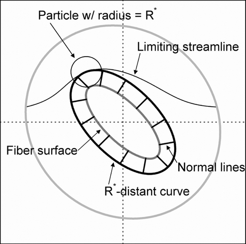
To calculate single-fiber interception efficiency for particular values of α, ϵ, Δ θ, and R*, the goal was to determine the maximum value of Ψ* at a distance R* from the surface of the fiber cross-section. Several steps were required to accomplish this. First, as shown in , a curve R* distant from the surface of the fiber was defined as the set of points R* from the fiber surface along lines normal to each point on the fiber surface. Second, the stream function for each point on the R* -distant curve was expressed in terms of χf and φf, the elliptical coordinates of the point on the fiber surface from which a normal line would pass through the point on the R* -distant curve. Third, the value of φf corresponding to the points on the R* -distant curve for which the maximum value of Ψ* occurred was found by computing the appropriate location where dΨ* /dφf = 0 numerically. Fourth, with the φf at which the maximum Ψ* occurred, the maximum value of Ψ* and the interception efficiency ηR,E were calculated. These steps will be described next in more detail.
FIG. 4 Surfaces and curves used to calculate single-fiber interception efficiency. The R* -distant curve is everywhere a distance R* from the fiber surface. The normal lines are normal to both the fiber surface and the R* -distant curve and connect points on the R* -distant curve to the corresponding closest points on the fiber surface. The limiting streamline intersects the R* -distant curve at only one point. The particle is shown at the location on the limiting streamline where it is intercepted by the fiber.
The equation of the ellipse for the surface of the fiber cross-section can be written in terms of xf and yf, the x and y coordinates on the fiber surface, as
By combining Equations (14) and (15) with the definitions for x and y in Equations (5) and (6), R* in Equation (Equation8), and the identities a2 = lf 2 – wf 2 and ϵ = lf/wf, expressions for the Cartesian coordinates of a point on the R* -distant curve can be developed in terms of the elliptical coordinates of the point on the surface of the fiber to which it is closest. These coordinates, non-dimensionalized by the half the distance between the foci, are
When the expressions in Equations (18)–(23) are substituted into Equation (Equation7), the non-dimensional stream function Ψ * at a non-dimensional distance R* from the surface of the fiber is defined in terms of Xp, Yp, and the parameters ϵ, α, and Δ θ. Because Xp and Yp vary only with χf, φf, R*, and ϵ and because χf depends only on ϵ, Ψ* on the R* -distant curve is defined as a function that varies exclusively with φf, a coordinate of the point on the fiber surface to which a particular point on the R* -distant curve is normal, when ϵ, α, and Δ θ are held constant. Finding the values of φf for which dΨ * /dφf = 0 on the R* -distant curve will allow determination of the value of φf for which Ψ* is a maximum on that curve. This value of Ψ* will be the maximum stream function for which a particle with a non-dimensional radius R* will be intercepted by the fiber.
Computation of dΨ* /dφf can be simplified by using the chain rule for partial derivatives (CitationThomas and Finney 1979):
To determine the maximum value of Ψ* on the R* -distant curve for a particular combination of ϵ, α, Δ θ, and R*, the value of Ψ* was calculated for 1° increments of φf ranging from 0° to 180° using Equation (Equation7) with values of χp, cosh χp, sinh χp, cos φp, and sin φp calculated using Equations (18)–(23). The values of φf that were 1° higher and lower than the value of φf that had the maximum Ψ* were utilized as the initial estimates for determining a more precise value of φf for which dΨ* /dφf = 0 using the secant method (CitationConte and de Boor 1980). The secant method is an iterative process that can be run according to the expression
Using code written by the author in Fortran 90 (Fortran PowerStation, Microsoft Corporation, Redmond, WA, USA), calculations of interception efficiency were performed for combinations of 10 values of ϵ ranging from 1.001 to 20, 10 values of α ranging from 0.004 to 0.25, 10 values of Δ θ ranging from 0° to 90°, and 31 values of R* ranging from 0.0001 to 100. All values utilized for these parameters are shown in . All levels of the four parameters would yield 31,000 separate combinations. However, for many of these combinations, particularly those with large ϵ, α, and R*, no limiting streamline existed within the flow field domain. Combinations of ϵ, α, and R* were excluded if the center of the particle could not pass through the solution domain without contacting the fiber when Δ θ was 90°. Mathematically, it can be stated that combinations of factors were excluded if
TABLE 1 Independent variables and their values for which single-fiber interception efficiency was computed numerically in a factorial design
These calculated efficiency values were used to develop an empirical expression for predicting ηR,E as a function of ηR,E(90°), α, ϵ, Δ θ, and R*. Expressions were developed using SAS 9.1.3 (SAS Institute, Cary, NC). The approach taken was to first develop an empirical expression for the ratio of the interception efficiency at Δ θ = 0° to ηR,E(90°), defined here as Ω, as a function of α, ϵ, and R*. The interception efficiency as a function of Δ θ for angles between 0° and 90° was then determined as a function of ηR,E(90°) and Ω. To linearize dependence of ηR,E on α, ϵ, Δ θ, and R* as much as possible, many variable transforms were attempted. An additional requirement for the final solution was that the expression for ηR,E must simplify to the expression for ηR,E(90°) from Equation (Equation9) when Δ θ = 90°. Furthermore, it was required that the efficiency not vary substantially as a function of Δ θ as ϵ → 1.
RESULTS
The empirical equation developed for single-fiber interception efficiency from the results of the numerical computations is
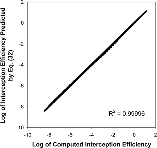
shows the logarithm of the interception efficiency calculated from Equation (Equation32) for each set of conditions modeled numerically using the Fortran program plotted against the efficiency predicted using the program. shows all 22,850 comparisons. The R2 for this relationship is 0.99996, indicating that Equation (Equation32) does an excellent job predicting the computed interception efficiency. No prediction from Equation (Equation32) differed by more than 30.8% from the value computed numerically. Moreover, 99.8% of the predictions were within 20% of the computed values, 98.1% were within 10%, and 86.2% were within 5%.
FIG. 5 The logarithm of single-fiber interception efficiency predicted using empirically developed Equation (Equation32) plotted against the logarithm of interception efficiency computed using numerical methods.
, , , show the influence of Δ θ, ϵ, and α on the relationship between ηR,E and R*. shows results of single-fiber interception efficiency versus particle diameter for ϵ = 6 and α = 0.016 at Δ θ = 0°, 30°, 60°, and 90°. The fibers were assumed to have the same cross-sectional area as a 3 μ m-diameter circular fiber. For ϵ = 6, this would indicate a fiber with a major axis approximately 7.3 μ m long and a minor axis about 1.2 μ m long.
FIG. 6 Single-fiber interception efficiency versus particle diameter for several orientation angles. In all cases, aspect ratio is 6, solidity is 0.016, and the cross-sectional area is equivalent to that of a circular fiber with a 3 μ m diameter, about 7.07 μ m2.
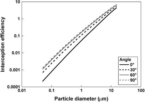
FIG. 7 Single-fiber interception efficiency versus particle diameter for several aspect ratios. In all cases, orientation angle is 90°, solidity is 0.016, and the cross-sectional area is equivalent to that of a circular fiber with a 3 μ m diameter, about 7.07 μ m2.
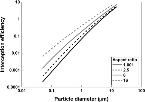
FIG. 8 Single-fiber interception efficiency versus particle diameter for several aspect ratios. In all cases, orientation angle is 0°, solidity is 0.016, and the cross sectional area is equivalent to that of a circular fiber with a 3 μ m diameter, about 7.07 μ m2.
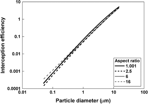
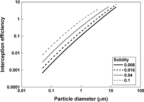
FIG. 9 Single-fiber interception efficiency versus particle diameter for several values of solidity. In all cases, aspect ratio is 6, orientation angle is 90°, and the cross-sectional area is equivalent to that of a circular fiber with a 3 μ m diameter, about 7.07 μ m2.
and present interception efficiency versus diameter for various values of ϵ for α = 0.016 and a cross-sectional area equivalent to a circular fiber with a 3 μ m diameter. assumes Δ θ = 90°, the major axis perpendicular to the incoming air flow, whereas assumes Δ θ = 0°, the major axis parallel to the air flow.
shows results of single-fiber interception efficiency versus particle diameter for ϵ = 6 and Δ θ = 90° with α = 0.006, 0.016, 0.04, and 0.1. The fibers again have the same cross-sectional area as a 3 μ m-diameter circular fiber.
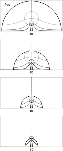
, , , present the limiting streamlines for particles 1, 3, and 9 μ m in diameter collected by elliptical fibers for the conditions plotted in –, respectively. In addition, the figures show the position of the particles along the streamlines where they contact the fiber. In and , the 9 μ m diameter particles are not shown because no limiting streamlines exist in the solution domains.
FIG. 10 Limiting streamlines for particles 1, 3, and 9 μ m in diameter plotted for conditions corresponding to . Orientation angles are (a) 0°, (b) 30°, (c) 60°, and (d) 90°. In all cases, aspect ratio is 6, solidity is 0.016, and the cross-sectional area is equivalent to that of a circular fiber with a 3 μ m diameter. The particles associated with each streamline are shown at the position at which they just touch the elliptical fiber.
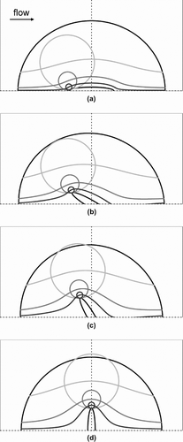
FIG. 11 Limiting streamlines for particles 1, 3, and 9 μ m in diameter plotted for conditions corresponding to . Aspect ratios are (a) 1.001, (b) 2.5, (c) 6, and (d) 16. In all cases, orientation angle is 90°, solidity is 0.016, and the cross-sectional area is equivalent to that of a circular fiber with a 3 μ m diameter. The particles associated with each streamline are shown at the position at which they just touch the elliptical fiber.
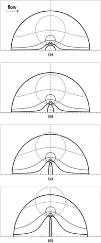
FIG. 12 Limiting streamlines for particles 1, 3, and 9 μ m in diameter plotted for conditions corresponding to . Aspect ratios are (a) 1.001, (b) 2.5, (c) 6, and (d) 16. In all cases, orientation angle is 0°, solidity is 0.016, and the cross-sectional area is equivalent to that of a circular fiber with a 3 μ m diameter. The particles associated with each streamline are shown at the position at which they just touch the elliptical fiber.
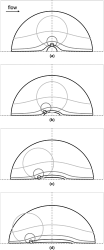
FIG. 13 Limiting streamlines for particles 1, 3, and 9 μ m in diameter plotted for conditions corresponding to . Solidity values are (a) 0.006, (b) 0.016, (c) 0.04, and (d) 0.1. In all cases, aspect ratio is 6, orientation angle is 90°, and the cross-sectional area is equivalent to that of a circular fiber with a 3 μ m diameter. The particles associated with each streamline are shown at the position at which they just touch the elliptical fiber. Particles 9 μ m in diameter are not presented in (c) and (d) because no limiting streamline passed through the solution domain.
DISCUSSION
demonstrates that ηR,E increases as particle diameter increases. Furthermore, the figure shows that ηR,E increases as Δ θ increases when ϵ ≠ 1. indicates that η R,E increases with Δ θ because the gradient of velocity along the line normal to the fiber surface at the point of interception increases with increasing Δ θ as the major axis of the elliptical cross-section becomes more perpendicular to the incoming air flow. In short, more air flows near the surface as Δ θ increases. The interception efficiency increases roughly in proportion to the projected area of the fiber in the direction of air flow. Thus, a much bigger increase in ηR,E is observed between Δ θ = 0° and Δ θ = 30° than between Δ θ = 60° and Δ θ = 90°. also shows that the effect of the velocity gradient is more important for smaller particles than for larger ones. Therefore, the differences in for interception efficiency as a function of Δ θ are greater for smaller particles than for larger ones.
indicates that ηR,E increases substantially as ϵ increases when Δ θ = 90°. demonstrates that the reason for this is the same as the reason for the increase in ηR,E with increasing Δ θ in : as ϵ increases, the gradient of velocity along the line normal to the fiber surface at the point of interception increases. As in , this increase is more pronounced in for smaller particles than for larger ones. In , therefore, the range of ηR,E is much greater on a percentage basis for smaller particles than for larger ones.
shows that ηR,E varies much less with ϵ when Δ θ = 0° than when Δ θ = 90°. The relationship between ηR,E and ϵ is also more complicated at Δ θ = 0°. Although efficiency decreases at all particle sizes as ϵ increases from 1.001 to 2.5, the efficiency generally increases as aspect ratio gets larger, particularly for the smaller particle sizes. The figure indicates that the interception efficiency for ϵ = 16 is larger than the efficiency for ϵ = 1.001 for particles smaller than 1 μ m in diameter. These results are unexpected. Elliptical fibers with large aspect ratios would be expected to block less of the flow at Δ θ = 0° and show a smaller interception efficiency than fibers with small aspect ratios. However, as illustrates, the dependence of ηR,E on the value of φ at which the limiting streamline passes closest influences results considerably. As ϵ increases, the point of interception moves closer to the forward edge of the fiber, which reduces the influence of ϵ on ηR,E. The shifts in the value of φ at which interception occurs also account for the crossing of the curves in .
shows that ηR,E increases as α increases. As indicates, this happens because the streamlines are compressed as α increases, making it more likely that particles will touch the fiber. also demonstrates that limiting streamlines do not exist for many larger particles as α increases. This is the equivalent in a real filter of particles being too large to pass through the voids between fibers.
It should be noted that CitationRaynor (2002) developed the equations for flow around elliptical fibers assuming the air around the fiber is a continuum. This assumption allowed a boundary condition of zero velocity, or no slip, on the surface of the fiber. As characteristic dimensions of the fiber approach the mean free path of the air molecules, the continnum assumption breaks down and slip flow occurs (CitationPich 1971). With slip flow assumptions, the velocity is not zero on the fiber surface. Pich defined the slip flow regime for circular cross-section fibers as beginning when Kn, the Knudsen number defined as the mean free path divided by the fiber radius, was greater than 0.001. More recently, CitationKosmider and Scott (2002) recommended applying slip flow assumptions to air flow modeling around fibers for Kn > 0.1. At standard atmospheric conditions, the computations performed for – were equivalent to Kn = 0.044 for the characteristic fiber dimension (lfwf).5ex1−.1em/−.15em.25ex 2/2. Although these conditions do not appear to require use of slip flow assumptions in the flow model according to Kosmider and Scott, small effects of slip are likely near the fiber surface and are not captured in the calculations for –.
CONCLUSIONS
Using a velocity field for flow around a fiber with an elliptical cross-section, expressions were developed for predicting single fiber efficiency for particles collected by elliptical fibers by the interception mechanism. As with circular fibers, interception efficiency increases with increasing particle diameter. Interception is most efficient for elliptical fibers having large aspect ratios when the major axis of the cross-section is oriented perpendicular to the incoming flow. Efficiency is enhanced when the filters are packed tightly. Although the expressions for elliptical fiber interception efficiency are complicated, they can be programmed into a computer spreadsheet program for repetitive calculations.
REFERENCES
- Adamiak , K. 1999 . Viscous Flow Model for Charged Particle Trajectories Around a Single Square Fiber in an Electric Field . IEEE Trans. Ind. Appl. , 35 : 352 – 358 .
- Brown , R. C. 1984 . A Many-Fibre Model of Airflow Through a Fibrous Filter . J. Aerosol Sci. , 15 : 583 – 593 .
- Conte , S. D. and de Boor , C. 1980 . Elementary Numerical Analysis: An Algorithmic Approach, , 3rd ed. , 78 – 79 . New York : McGraw-Hill .
- Fardi , B. and Liu , B. Y. H. 1992a . Flow Field and Pressure Drop of Filters with Rectangular Fibers . Aerosol Sci. Technol. , 17 : 36 – 44 .
- Fardi , B. and Liu , B. Y. H. 1992b . Efficiency of Fibrous Filters with Rectangular Fibers . Aerosol Sci. Technol. , 17 : 45 – 58 .
- Hinds , W. C. 1999 . Aerosol Technology: Properties, Behavior, and Measurement of Airborne Particles, , 2nd ed. , 190 – 196 . New York : Wiley-Interscience .
- Hutten , I. M. 2007 . Handbook of Nonwoven Filter Media , 103 – 194 . Amsterdam : Elsevier .
- Kirsch , A. A. and Fuchs , N. A. 1967 . The Fluid Flow in a System of Parallel Cylinders Perpendicular to the Flow Direction at Small Reynolds Numbers . J. Physical Society Japan , 22 : 1251 – 1255 .
- Kosmider , K. and Scott , J. 2002 . Polymeric Nanofibers Exhibit an Enhanced Air Filtration Performance . Filtr. Sep. , 39 : 20 – 22 .
- Kuwabara , S. 1959 . The Forces Experienced by Randomly Distributed Parallel Circular Cylinders or Spheres in a Viscous Flow at Small Reynolds Numbers . J. Physical Society Japan , 14 : 527 – 532 .
- Ouyang , M. and Liu , B. Y. H. 1998 . Analytical Solution of Flow Field and Pressure Drop for Filters with Rectangular Fibers . J. Aerosol Sci. , 29 : 187 – 196 .
- Pich , J. 1966 . “ Theory of Aerosol Filtration by Fibrous and Membrane Filters ” . In Aerosol Science , Edited by: Davies , C. N. 223 – 285 . New York : Academic Press .
- Pich , J. 1971 . Pressure Characteristics of Fibrous Aerosol Filters . J. Colloid Interface Sci. , 37 : 912 – 917 .
- Raynor , P. C. 2002 . Flow Field and Drag for Elliptical Filter Fibers . Aerosol Sci. Technol. , 36 : 1118 – 1127 .
- Thomas , G. B. and Finney , R. L. 1979 . Calculus and Analytic Geometry, , 5th ed. , 600 – 601 . Reading, MA : Addison-Wesley .
- Wang , C. Y. 1996 . Stokes Flow Through an Array of Rectangular Fibers . Int. J. Multiphase Flow , 22 : 185 – 194 .
- Zhu , C. , Lin , C. H. and Cheung , C. S. 2000 . Inertial Impaction-Dominated Fibrous Filtration with Rectangular or Cylindrical Fibers . Powder Technol. , 112 : 149 – 162 .