Abstract
The deliquescence of sodium chloride is size dependent for particles smaller than 100 nm, with some discrepancies between measured and predicted deliquescence relative humidity as a function of size. Two sources of uncertainty in current models are the solid–liquid/solid–vapor surface tensions and the curvature dependence of surface tension. Molecular Dynamics simulations are used to calculate surface tensions and their corresponding upper bounds, which compare well with measured values of liquid–vapor (LV) interfaces and significantly reduce uncertainty compared to experimental estimates of solid–liquid (SL) and solid–vapor (SV) interfaces. Surface tensions calculated for nanoparticles in the 2–10 nm size range are related to the corresponding flat interface values using the first-order Tolman length ( δ ). At 1 atm and 300 K, the Tolman length determined from the test-area method is of the order of 0.1 nm with a precision between 5% and 10%. The δ LV (water–air) is 0.15 nm, δ LV (soln–air) is 0.10 nm, δ SL (NaCl–soln:) is 0.13 nm, and δ SV (NaCl–air) is 0.14 nm, with positive values corresponding to a decrease in surface tension for smaller particles. The size-dependent deliquescence relative humidity is calculated using a thermodynamic model of water uptake with these new surface tension estimates and with Tolman length corrections. The reduced uncertainties in surface tension significantly improve agreement with measured deliquescence relative humidity of sodium chloride nanoparticles with 5–150 nm diameters. The size-dependent corrections to surface tension produce a minor improvement in the comparison of predicted and measured deliquescence relative humidity of particles smaller than 3 nm.
I. INTRODUCTION
Sodium chloride is the major component of sea salt particles, which are a significant component in atmospheric aerosols (CitationHeintzenberg 1989). The hygroscopic growth of these particles has important consequences for climate, by forming haze and clouds and affecting atmospheric radiative transfer (CitationAdams et al. 2001). Nanoparticles also play a significant role in atmospheric chemistry (CitationFinlayson-Pitts and Hemminger 2000; CitationHoffmann et al. 2003; CitationMartin 2000; CitationVaknin et al. 2004) by forming solid–vapor and solution–vapor interfaces that serve as sites for surface or aqueous phase reactions. Most studies of hygroscopic behavior of particles involve determination of the relative humidity at which water uptake is initiated, i.e., deliquescence relative humidity (DRH), and the total amount of water accreted, i.e., hygroscopic growth factor (HGF). These studies have focused on particles with initial dry diameters of 100 nm or greater (CitationCruz and Pandis 2000; CitationDavis 1995; Defay et al. 1996; CitationTang et al. 1986). However, recent advances in experimental methods for detecting particles and limiting trace contaminants have prompted both experimental measurements (CitationBiskos et al. 2006; CitationHämeri et al. 2000) and numerical models (CitationMirabel et al. 2000; CitationRussell and Ming 2002) in the nanosize regime, where a strong size dependence of hygroscopic properties is evident.
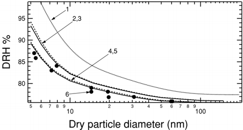
The coated particle model (CitationRussell and Ming 2002) represents the nanoparticle as a solid core surrounded by a solution-like layer prior to deliquescence and correctly reproduces the observed trend of increasing DRH with decreasing particle size, but the magnitude of this effect is over-predicted for particles smaller than 10 nm (CitationBiskos et al. 2006). As illustrated in , a major source of this discrepancy is uncertainty in surface tension of the solid–liquid and solid–vapor interfaces. CitationRussell and Ming (2002) estimated the surface tension from a range of existing indirect measurements (CitationHeslot et al. 1990; CitationPrisciandaro et al. 2001; Wu and Nancollas 1999). The surface tension is expected to be size dependent in the nanosize regime (CitationGibbs 1948; CitationKoenig 1950; CitationTolman 1949). In a previous study, we have reduced the uncertainty in solid–liquid surface tension by estimating a value and a corresponding upper bound from molecular dynamics simulations (CitationBahadur et al. 2007). In Section II, we extend our technique for calculating surface tensions to particles smaller than 15 nm. In Section III, we use the coated particle model and size corrected surface tensions to calculate DRH dependence on size for sodium chloride particles for comparison with experimental measurements.
FIG. 1 The DRH for NaCl particles determined for a range of sizes between 5 and 150 nm. (1) The dotted line is calculated using surface tensions within the experimental range (CitationRussell and Ming 2002). (2,3) DRH calculated using upper bounds of surface tension (CitationBahadur et al. 2007) for σSL = 59 mNm−1 and for σLV = 89 mNm−1. The solid line (2) is calculated using bulk values and the dashed line (3) includes Tolman corrections to the surface tension. (4,5) DRH calculated using solid-liquid surface tension calculated in this work for σSL = 59 mNm−1 and measured liquid-vapor surface tension of σLV = 80 mNm−1. The solid line (4) uses bulk values and dashed line (5) includes Tolman corrections. (6) Solid circles show measured NaCl DRH for nanoparticles (CitationBiskos et al. 2006).
II. SURFACE TENSION SIZE DEPENDENCE
The dependence of the surface tensions of vapor bubbles and liquid droplets on the radius of curvature of the dividing surface is the subject of numerous theoretical (CitationBaidakov and Boltachev 1999; CitationBaidakov et al. 2004; CitationBlokhuis and Bedeaux 1992a; CitationBlokhuis and Bedeaux 1992b; CitationGibbs 1948; CitationKoenig 1950; CitationTolman 1949) and experimental (CitationBarrett 2006; CitationFisher and Israelachvili 1979; CitationWingrave et al. 1981) investigations. The various methods used to determine the size dependence of surface tension have not yet yielded definitive results for either the sign or magnitude of the variation. For an interface curved sufficiently weakly, the size dependence of the surface tension is (CitationBlokhuis and Bedeaux 1992a)
While measurements provide adequate characterization of liquid–vapor interfaces, the relative nondeformability of the solid phases restricts measurements of solid–liquid and solid–vapor surface tensions (CitationHeslot et al. 1990; Wu and Nancollas 1999) to those inferred from measurements of related surface-driven phenomena (such as solubility and crystallization). Such measurements have severe experimental uncertainties (CitationHarbury 1946; CitationHiemenz 1986; CitationPrisciandaro et al. 2001) and rely on theoretical models to infer the surface tension indirectly. Molecular simulation techniques do not suffer from this limitation and provide a convenient methodology to directly study the interfacial profile between two coexisting fluids or between a fluid and an adjacent solid surface (CitationAlejandre et al. 1995; CitationMatsumoto and Kataoka 1987; CitationNicholson and Parsonage 1982; CitationRowlinson and Widom 1982; CitationZykova-Timan et al. 2005). Computational studies of sodium chloride solutions (CitationJungwirth and Tobias 2001; CitationKoneshan and Rasaiah 2000; CitationLisal et al. 2005; CitationLyubartsev and Laaksonen 1996; CitationOhtaki and Radnal 1993), interfaces between solid NaCl and water (CitationShinto et al. 1998a; CitationShinto et al. 1998b), and NaCl in contact with a supersaturated solution (CitationOyen and Hentschke 2002) have detailed the effect of number of simulated molecules, range of molecular interaction, various idealized potentials, system geometry, and corrections for long-range interactions on the simulation results. The ready availability of both well-developed simulation techniques and potentials makes MD accurate and efficient for calculating surface tensions in the NaCl-water-air system.
A. Surface Tension Calculations from MD
Surface tension can be calculated using two general classes of techniques applicable at ambient atmospheric conditions. The first and most widespread is the mechanical technique based on the components of the pressure tensor associated with a planar interface. For an interface perpendicular to the z axis, the surface tension is given by
The second class of techniques determines surface tension based on the thermodynamic work of formation of the interface. These techniques have the advantage of being easily modified for curved interfaces, making them ideal for simulating finite particles. In a constant temperature and pressure ensemble (NPT), the surface tension of an interface between two co-existing phases αand βat equilibrium can be defined in terms of a Gibbs free energy difference per unit area,
The energy difference method rewrites Equation (Equation5) using the relation between Gibbs free energy and enthalpy, such that the surface tension is calculated using the enthalpy (which can be readily simulated) and a correction due to excess surface entropy, i.e.,
The test-area method developed by CitationGloor et al. (2005) allows direct calculation of surface tension without a significant increase in computational costs over the energy difference method. The perturbations in the Helmholtz free energy of a simulation cell due to a small perturbation in the total interfacial area of a reference state are calculated, keeping all other properties constant. An accurate estimate of the surface tension can be obtained as
B. Molecular Dynamics Simulations
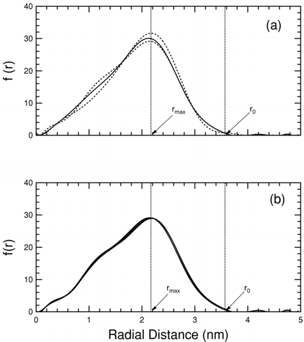
The simulation setup for a planar interface consists of slabs of the two phases of interest in contact replicated with periodic boundary conditions. The cells are set up such that the conditions n αβ = n α + n β and V αβ = V α + V β are satisfied, placing the plane of separation on the physical interface. The model represents a series of parallel semi-infinite interfaces, eliminating curvature effects. The simulation setup for determining the surface tension of a curved interface extends this idea, by replacing the two slabs in contact by a particle of one phase embedded in the other. The thermodynamic treatment of the energy difference method remains identical with the interfacial area in this case being the actual surface area of the surrounded particle. The test-area method is implemented using three simulation cells with the nanoparticles in each constructed with an equal number of molecules, but different surface areas such that A 2 = A 1(1+ 0.005) and A 3 = A 1(1−0.005). The interface is altered by re-scaling the coordinates of the individual molecules such that the volume of the relevant phase is appropriately perturbed. MD simulations of the reference and perturbed cells are carried out for an identical number of steps. Molecular coordinates are recorded at regular intervals and treated as snapshots comprising the ensemble average (CitationBahadur et al. 2007). The surface area of the nanoparticles for both methods is determined by plotting the histogram of the radial distribution of molecules around the particle center, as illustrated in . For a cubic particle, the surface area can be shown to be 24r 2 max, or equivalently 12r 2 0 where r max is the radial distance at which the frequency is a maximum, and r 0 the radial distance at which the frequency drops to 0. shows that distributions determined at five different times during a simulation are nearly indistinguishable, indicating nearly constant surface area with only minor statistical fluctuations.
FIG. 2 Frequency of particle occurrence as a function of radial distance from the average particle center for an example NaCl particle with 3.5 nm edge length. For clarity polynomial fits are shown in this figure. The tail-end peaks are artifacts of the fit, and not a real part of the distribution. Part (a) shows the radial distribution in the test-area method for the reference (solid line) state, and the perturbed (dashed lines) states. Part (b) shows the radial distribution of the reference state at 1, 2, 3, 4, and 5 ns. The lines are colinear.
MD simulations are performed using DL POLY version 2.14 (CitationForester and Smith 1995) in an NVT ensemble for the test-area method and an NPT ensemble for the energy-difference method. The number of molecules included in a simulation cell are determined from measured bulk density of the appropriate phase. The temperature and pressure (where applicable) are held constant at 300 K and 1 atm using the Nosé-Hoover algorithm (CitationHoover 1985; Nosé 1984). All interatomic interactions in the simulation box are calculated within a cutoff distance of 10° A, and the Coulombic long-range interactions are calculated using Ewald's method (CitationAllen and Tildesley 1987; CitationFrenkel and Smit 2000; CitationGibson and Scheraga 1995; CitationRappaport 1987). Simulation cells are cubic with an edge length equal to the embedded particle diameter plus 30 Å and replicated with periodic boundary conditions. The simulation cell edge length and number of molecules in the particle and surrounding phase are listed in for representative examples. Simulations are performed using a time step of 0.75 fs, for a total of 8 × 10⁶ steps (6 ns). The combined system is allowed to equilibrate for 100,000 time steps (75 ps) before thermodynamic properties of the resulting mixture are calculated and recorded after every 5000 simulation steps.
TABLE 1 Simulation cell edge length and number of included molecules
The ion-ion interactions in the simulation are modeled using the Born-Huggins-Mayer potential (CitationHuggins and Mayer 1933), which contains both attractive and repulsive terms, and has been used to successfully model spherical molecules. Water molecules are described using the TIP4P potential model (CitationJorgensen et al. 1983), which describes the polar nature of the water molecule most efficiently. Ion-water interactions are modeled using Lennard-Jones (LJ) type interactions (CitationSmith and Dang 1994). Air is modeled using a 4:1 mixture of nitrogen and oxygen molecules that also interact using the LJ potential. The amount of water vapor in the air phase is small, and its minor influence is neglected. Cross terms for all LJ interactions are calculated using the Lorentz-Berthelot combination rules, i.e., ε ij = ε ii ε jj and σ ij = σ ii + σ jj /2. Further simulation details and parameters values used for the potentials are provided in earlier work (CitationBahadur et al. 2006; Citation2007).
C. Tolman Length
The energy difference and test-area methods provide two alternate pathways for calculating surface tension that allow for inter-comparison between model values. Results from the two methods show good agreement with each other and compare well with experimental measurements (CitationBahadur et al. 2007). Calculated surface tensions for planar interfaces from both methods are summarized in . These values in conjunction with new simulation results for nanoparticles can be used in Equation (Equation3) to determine the size dependence of surface tension. The Tolman length can be determined from either method, providing another basis for comparison for the model results.
TABLE 2 Calculated surface tensions in NaCl-Air-water system
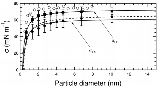
The curvature dependence of the air-water surface tension (from the test-area method) and its corresponding upper bound (from the energy difference method) is shown in . Experimental values are included for comparison (CitationWingrave et al. 1981). The calculated values are smaller than the measured values, as reported in other studies using the TIP4P potential used to model water (CitationIsmail et al. 2006). To quantify the Tolman length, the calculated surface tensions are fit to Equation (Equation3) such that
FIG. 3 Variation in water–air surface tension as a function of water particle diameter. Solid squares are surface tension upper bounds from the energy difference method, solid circles are surface tensions from the test-area method (both from this work), and empty circles correspond to measurements (CitationWingrave et al. 1981). The solid curved lines correspond to a two-parameter fit using Equation (Equation3) allowing both σ0 and δ to vary. Associated dashed lines are single-parameter fits obtained by holding σ0 constant at the calculated values listed in . All values of surface tension and Tolman length are summarized in .
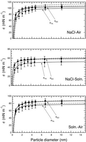
shows the curvature effect in the NaCl–solution, NaCl–air, and solution–air interfaces. The surface tension decreases with decreasing size for all three systems, corresponding to positive Tolman lengths. A significant drop in surface tension for these three interfaces occurs only for particles smaller than approximately 2 nm, as in the water–air interface. The upper bounds from the energy difference method show a slightly weaker size dependence than the corresponding surface tensions obtained from the test-area method but follow a similar trend. The Tolman length determined using two different fit methods is similar in each case, except for the solid NaCl particles where the discrepancy results from using a value of surface tension with a large uncertainty range as a fixed parameter. Values of σ0 and δ for each interface are listed in . The calculated length parameters have a precision between 5% and 10%, based on one standard deviation in the fitting parameters from Equation (Equation8).
TABLE 3 Surface tensions and Tolman lengths from one (OP) and two (TP) parameter fits.
FIG. 4 Variation in surface tension as a function of particle size. The interface in each case exists between a particle of the more condensed phase embedded in the more diffuse phase. Solid squares show surface tension upper bounds from the energy difference method and solid circles are surface tensions from the test-area method. Solid lines correspond to a two parameter (TP) fit used to determine Tolman length, and dashed lines are a one parameter (OP) fit.
III. SENSITIVITY OF DELIQUESCENCE TO SURFACE TENSION
The prediction of water uptake by sodium chloride particles smaller than 100 nm in diameter from crystalline form to liquid particles involves knowledge of both particle size and surface energies (CitationRussell and Ming 2002). Since solid–liquid/solid–vapor surface tension values are not well known, a large range of values has been used in previous studies. The use of surface tensions and upper bounds calculated in a consistent manner has the additional advantage of reducing this uncertainty. CitationRussell and Ming (2002) developed the wetted particle thermodynamic model with distinct solid–liquid and liquid–vapor interfaces prior to water uptake rather than a single solid–vapor interface. The free energy change of deliquescence is then
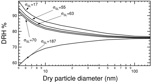
The deliquescence relative humidities for NaCl nanoparticles ranging in size between 5 nm and 150 nm were determined with this iterative calculation using available values for the solid–liquid and liquid–vapor surface tensions, with the liquid being saturated NaCl solution. shows DRH curves determined by holding the solid–liquid surface tension constant at 63 mNm−1 and varying the liquid–vapor surface tension over the entire range of possible values determined from experiments and calculations. The predicted DRH increases with decreasing particle size for the entire range of surface tensions considered. Lowering the liquid–vapor surface tension lowers the DRH for any given particle size, consistent with the wetted particle model since a smaller energetic cost must be paid for the creation of a (larger) liquid vapor interface. shows the complementary DRH curves determined by holding the liquid–vapor surface tension constant at 82 mNm−1 and varying the solid–liquid surface tension over the range of uncertainty. In this case, the opposing effect is observed, i.e., lowering the surface tension increases the DRH, since a smaller energetic benefit is gained by destroying the solid–liquid interface during deliquescence. For high enough values of surface tension smaller particles deliquesce at lower RHs than the expected DRH for large particles.
FIG. 5 Deliquescence relative humidity curves for NaCl at 300 K and 1 atm calculated using a bulk thermodynamic model (CitationRussell and Ming 2002). The solid–liquid surface tension is held constant at 63 mNm−1 and liquid-vapor surface tension is varied as indicated by tags.
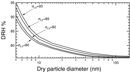
FIG. 6 Deliquescence relative humidity curves for NaCl at 300K and 1 atm calculated using a bulk thermodynamic model (CitationRussell and Ming 2002). The liquid–vapor surface tension is held constant at 82 mNm−1 and solid–liquid surface tension is varied as indicated by tags.
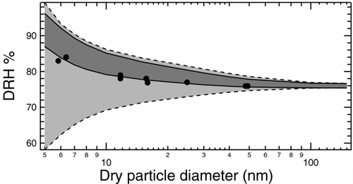
The combined effect of reducing the uncertainty in predicted DRH for sodium chloride by imposing upper bounds on possible solid–liquid/solid–vapor surface tension calculated in this work is illustrated in . Due to the ease and accuracy of measuring liquid–vapor surface tensions, the MD calculated upper bounds and surface tension estimates do not help to constrain the uncertainty (even though they are consistent with the measured values). Only experimental values for σLV are used in subsequent calculations. The region in which possible DRH curves may lie is bound by combining surface tension values that have complementary effects, i.e. the lowest solid–liquid surface tension combined with the highest liquid–vapor surface tension to determine the upper extrema, and vice versa. The region bound using only experimental values is significantly larger than the region bound using our calculated surface tensions, particularly since the uncertainty in measured solid–liquid surface tension allows for a decreasing DRH with decreasing particle size. The region of uncertainty grows with decreasing particle size (with all values converging to near-bulk DRH at large sizes), but the divergence is more extreme if only experimentally inferred values are used. At 50 nm, the range of possible DRHs is reduced from 74.7–78.6% (3.9%) to 75.7–77.8% (2.1%), with the reduction at 10 nm being from 69.2–86.2% (17.0%) to 79.1–85.1% (6.0%). DRH measurements (CitationBiskos et al. 2006), corrected with a shape factor for spheres, lie entirely inside or very close to the region prescribed by the values recommended by the test-area and energy difference methods. One outlier exceeds this range but is close to the upper bound. DRH calculations using the size correction to surface tension determined in Section II are illustrated in . The effect of Tolman length in these calculations is minor with DRHs calculated within 3% at all particle sizes, with and without a size correction for surface tension. This small difference is expected since the relative change in surface tension due to curvature is minor at sizes larger than 3 nm. Additionally, reduction in both solid-liquid and liquid-vapor surface tensions has opposing effects on DRH that partially cancel each other. The closest agreement between calculations and measurements is obtained by combining the experimentally reported lowest value of 80 mNm−1 for the liquid–vapor interface, with a value of 59 mNm−1 calculated as the upper bound for solid–liquid surface tension in this work. The divergence between measurements and predictions increases slightly at smaller sizes, but there is a higher degree of uncertainty associated with measurements of particles smaller than 5 nm (CitationBiskos et al. 2006).
FIG. 7 Region of possible size-dependent NaCl DRH curves at 300 K and 1 atm due to uncertainty in surface tension. The light grey region delimited by dashed lines represents the area determined based on extreme reported values of surface tension. The upper limit uses 85 mNm−1 for σLV and 17 mNm−1 for σSL and the lower limit uses 80 mNm−1 and 187 mNm−1, respectively. The dark grey region delimited by solid lines represents the area determined by combining the reported value of 80 mNm−1 for σLV with the possible extreme values of 56 and 63 mNm−1 for σSL calculated in this work. Shape-corrected measurements of DRH (CitationBiskos et al. 2006) shown as filled circles lie close to or within the dark grey region, which is entirely a subset of the light grey region.
IV. CONCLUSIONS
This work reports size-dependent surface tensions in the NaCl–water–air systems calculated using classical MD simulations at 300 K and 1 atm pressure and their effect on deliquescence properties. Two distinct thermodynamic techniques are utilized for calculating surface tension, with the energy difference method yielding upper bounds and the test-area method yielding surface tension values. The methods have been shown to have good accuracy for water-air and soln.-air σlv (±6 mNm−1 or 7%) and a much lower uncertainty than the current range of experimental results from indirect methods for σsv and σsl (CitationBahadur et al. 2007) for infinitely extended interfaces. Size-dependent results from both models are consistent with each other and with reported measurements. A first order size correction to the surface tension is accomplished by fitting calculations to the Tolman equation. The resulting Tolman lengths from both the energy difference and test-area methods are positive, indicating a decrease in surface tension with particle size, with magnitudes on the order of molecular sizes, i.e., 0.1 nm. The use of size-dependent surface tension from this work to predict DRH of NaCl nanoparticles results in improved agreement with measurements in the 5–150 nm size range. Uncertainties in the magnitude of the solid–liquid and liquid–vapor surface tension are shown to have opposing effects, with the solid–liquid effect dominating. The use of surface tension upper bounds from the energy difference method to determine DRH provides a significant improvement over results using reported measurements, with a further improvement by using solid-liquid and solid-vapor surface tensions determined from the test-area method. The effect of the Tolman correction is negligible for particles larger than 5 nm, but probably significant in nucleation and efflorescence phenomenon.
Acknowledgments
This material is based upon work supported by the National Science Foundation under Grant no. 0304213 and the James S. McDonnell Foundation. Any opinions, findings, and conclusions and recommendations are those of the authors and do not necessarily reflect the views of the National Science Foundation. We thank the San Diego Super Computing Institute (SDSC) for providing computational resources used in our calculations. We thank Saman Alavi for input and suggestions regarding this work.
Notes
c CitationFujii et al. 2005; CitationGaonkar and Neuman 1987; CitationHeller et al. 1966; CitationJasper 1972.
d CitationAbramzon and Gauberk 1993; CitationAdamson 1990; CitationHeller et al. 1966; Wu and Nancollas 1999.
a mNm−1.
b nm.
REFERENCES
- Abramzon , A. A. and Gauberk , R. D. 1993 . Surface Tension of Salt Solutions . Zh. Prikl. Khim. (St. Petersburg) , 66 : 1428
- Adams , P. J. , Seinfeld , J. H. , Koch , D. , Mickley , L. and Jacob , D. 2001 . General Circulation Model Assessment of Direct Radiative Forcing by the Sulphate-Nitrate-Ammonium-Water Inorganic Aerosol System . J. Geophys. Res. , 106 : 1097 – 1111 .
- Adamson , A. W. 1990 . Physical Chemistry of Surfaces , New York : Wiley .
- Alejandre , J. , Tildesley , D. J. and Chapela , G. A. 1995 . Molecular Dynamics Simulations of the Orthobaric Densities and Surface Tension of Water . J. Chem. Phys. , 102 : 4574 – 4583 .
- Allen , M. P. and Tildesley , D. J. 1987 . Computer Simulation of Liquids , New York : Oxford University Press .
- Bahadur , R. , Russell , L. M. and Alavi , S. 2007 . Surface Tensions in NaCl-Water-Air Systems from MD Simulations . J. Phys. Chem. B , 111 : 11989 – 11996 .
- Bahadur , R. , Russell , L. M. , Alavi , S. , Martin , S. T. and Buseck , P. R. 2006 . Void Induced Dissolution in Molecular Dynamics Simulations of NaCl and Water . J. Chem. Phys. , 124 : 154713-1 – 154713-9 .
- Baidakov , V. G. and Boltachev , G. S. 1999 . Curvature Dependence of the Surface Tension of Liquid and Vapor Nuclei . Phys. Rev. E , 59 : 469 – 475 .
- Baidakov , V. G. , Boltachev , G. S. and Chernykh , B. B. 2004 . Curvature Corrections to Surface Tension . Phys. Rev. E , 70 : 011603-1 – 011603-7 .
- Barrett , J. C. 2006 . Some Estimates of the Curvature Dependence of Surface Tension Using Density Functional Theory . J. Chem. Phys. , 124 : 144705-1 – 144705-6 .
- Biskos , G. , Malinowski , A. , Russell , L. M. , Buseck , P. R. and Martin , S. T. 2006 . Nanosize Effect on the Deliquescence an Efloroscence of Sodium Chloride Particles . Aerosol Sci. Tech. , 40 : 97 – 106 .
- Blokhuis , E. M. and Bedeaux , D. 1992a . Derivation of Microscopic Expressions for the Rigidity Constants of a Simple Liquid-Vapor Interface . Physica A , 184 : 42 – 70 .
- Blokhuis , E. M. and Bedeaux , D. 1992b . Pressure Tensor of a Spherical Interface . J. Chem. Phys. , 97 : 3576 – 3586 .
- Cruz , C. N. and Pandis , S. N. 2000 . Deliquescence and Growth of Mixed Inorganic-Organic Atmospheric Aerosol . Environ. Sci. Tech. , 34 : 4313 – 4319 .
- Davis , H. T. 1995 . Statistical Mechanics of Phases, Interfaces, and Thin Films , New York : VCH Publishers .
- Defay , R. , Prigogine , I. and Bellemans , A. 1966 . Surface Tension and Adsorption , London : Longmans Green .
- Finlayson-Pitts , B. J. and Hemminger , J. C. 2000 . Physical Chemistry of Airborne Sea Salt Particles and Their Components . J. Phys. Chem. A , 104 : 11463 – 11477 .
- Fisher , L. R. and Israelachvili , J. N. 1979 . Dirext Experimental Verification of the Kelvin Equation for Capillary Condensation . Nature , 277 : 548 – 549 .
- Forester , T. R. and Smith , W. , eds. 1995 . DLPOLY 2.14 (CCLRC)
- Frenkel , D. and Smit , B. 2000 . Understanding Molecular Simulation , New York : Academic .
- Fujii , H. , Matsumoto , T. , Ueda , T. and Nogi , K. 2005 . A New Method for Simultaneous Measurement of Surface Tension and Viscosity . J. Mat. Sci. , 40 : 2161 – 2166 .
- Gaonkar , A. G. and Neuman , R. D. 1987 . The Uncertainties in Absolute Value of Surface Tension of Water . Coll. and Surf. , 27 : 1 – 14 .
- Gibbs , J. W. 1948 . Collected Works , New Haven, CT : Yale University Press .
- Gibson , K. D. and Scheraga , H. A. 1995 . Crystal Packing Without Symmetry Constraints. 1. Tests of a New Algorithm for Determining Crystal Structures by Energy Minimization . J. Phys. Chem. , 99 : 3752 – 3764 .
- Gloor , G. J. , Jackson , G. , Blas , F. J. and de Miguel , E. 2005 . Test Area Simulation Method for the Direct Determination of the Interfacial Tension of Systems with Continuous or Discontinuous Potentials . J. Chem. Phys. , 123 : 134703-1 – 134703-19 .
- Hämeri , K. , Väkevä , M. , Hansson , H.-C. and Laaksonen , A. 2000 . Hygroscopic Growth of Ultrafine Ammonium Sulphate Aerosol Measured Using an Ultrafine Tandem Mobility Analyzer . J. Geophys. Res. , 105 : 22231 – 22242 .
- Harbury , L. 1946 . Solubility and Melting Point as Function of Particle Size . J. Phys. Chem. , 50 : 190 – 199 .
- Heintzenberg , J. 1989 . Particle Size Distribution and Optical Properties of Arctic Haze . Tellus , 32 : 251 – 260 .
- Heller , W. , Cheng , M. H. and Greene , B. W. 1966 . Surface Tension Measurements by Means of the Microcone Tensiometer . J. Colloid. Inter. Sci. , 22 : 179 – 194 .
- Heslot , F. , Cazabat , A. M. , Levinson , P. and Fraysse , N. 1990 . Experiments on Wetting on the Scale of Nanometers Influence of the Surface Energy . Phys. Rev. Lett. , 65 : 599 – 602 .
- Hiemenz , P. C. 1986 . Principles of Colloid and Surface Chemistry , New York : Dekker Inc. .
- Hoffman , R. C. , Kaleuati , M. A. and Finlayson-Pitts , B. J. 2003 . Knudsen Cell Studies of the Reaction of Gaseous HNO3 with NaCl Using Less Than a Single Layer of Particles at 298 K: A Modified Mechanism . J. Phys. Chem. A , 107 : 7818 – 7826 .
- Hoover , W. G. 1985 . Canonical Dynamic Equilibrium Phase Space Distributions . Phys. Rev. A , 31 : 1695 – 1697 .
- Huber , P. J. 1981 . Robust Statistics , New York : Widom, Wiley .
- Huggins , L. and Mayer , J. E. 1933 . Interatomic Distances in Crystals of the Alkali Halides . J. Chem. Phys. , 1 : 643 – 646 .
- Ismail , A. E. , Grest , G. S. and Stevens , M. J. 2006 . Capillary Waves at the Liquid-Vapor Interface and the Surface Tension of Water . J. Chem. Phys. , 125 : 014702-1 – 014702-10 .
- Jasper , J. J. 1972 . The Surface Tension of Pure Liquid Compounds . J. Phys. Chem. Ref. Data , 1 : 841 – 1009 .
- Jorgensen , W. L. , Chandrasekhar , J. , Madura , J. D. , Impey , R. W. and Klein , M. L. 1983 . Comparison of Simple Potential Functions for Simulating Liquid Water . J. Chem. Phys. , 79 : 926 – 935 .
- Jungwirth , P. and Tobias , D. J. 2001 . Molecular Structure of Salt Solutions: A New View of the Interface with Implications for Heterogeneous Atmospheric Chemistry . J. Phys. Chem. B , 105 : 10468 – 10475 .
- Koenig , F. O. 1950 . On the Thermodynamic Relationship Between Surface Tension and Curvature . J. Chem. Phys. , 18 : 449 – 459 .
- Koneshan , S. and Rasaiah , J. C. 2000 . Computer Simulations of Aqueous Sodium Chloride Solutions at 298 K and 683 K . J. Chem. Phys. , 113 : 8125 – 8137 .
- Laird , B. B. and Davidchack , R. L. 2005 . Direct Calculation of the Crystal Melt Interfacial Free Energy via Molecular Dynamics Computer Simulations . J. Phys. Chem. B , 109 : 17802 – 17812 .
- Lisal , M. , Smith , W. R. and Kolafa , J. 2005 . Molecular Simulations of Aqueous Electrolyte Solubility. 1. The Expanded Ensemble Osmotic Molecular Dynamics Method for the Solution Phase . J. Phys. Chem. B , 109 : 12956 – 12965 .
- Lyubartsev , A. P. and Laaksonen , A. 1996 . Concentration Effects in Aqueous NaCl Solutions a Molecular Dynamics Simulation . J. Phys. Chem. , 100 : 16410 – 16418 .
- Martin , S. T. 2000 . Phase Transitions of Aqueous Atmospheric Particles . Chem. Rev. , 100 : 3403 – 3453 .
- Matsumoto , M. and Kataoka , Y. 1987 . Study on Liquid-Vapor Interfaces of Water. I. Simulational Results of Thermodynamic Properties and Orientational Structure . J. Chem. Phys. , 88 : 3233 – 3245 .
- Mirabel , P. , Reiss , H. and Bowles , R. K. 2000 . A Theory for the Deliquescence of Small Particles . J. Chem. Phys. , 113 : 8200 – 8205 .
- Nicholson , D. and Parsonage , N. G. 1982 . Computer Simulation and Statistical Mechanics of Adsorption , New York : Academic .
- Nose , S. 1984 . A Unified Formulation of the Constant Temperature Molecular Dynamics Methods . J. Chem. Phys. , 81 : 511 – 519 .
- Ohtaki , H. and Radnal , T. 1993 . Structure and Dynamics of hydrated ions . Chem. Rev. , 93 : 1157 – 1204 .
- Oyen , E. and Hentschke , R. 2002 . Molecular Dynamics Simulations of Aqueous Sodium Chloride Solution at the NaCl(100) Interface with a Polarizable Water Model . Langmuir , 18 : 547 – 556 .
- Prisciandaro , M. , Lancia , A. and Musmarra , D. 2001 . Gypsum Nucleation into Sodium Chloride Solutions . AIChE J. , 47 : 929 – 934 .
- Rappaport , D. C. 1987 . The Art of Molecular Dynamics Simulations , New York : Cambridge University Press .
- Rowlinson , J. S. and Widom , B. 1982 . Molecular Theory of Capillarity , Clarendon .
- Russell , L. M. and Ming , Y. 2002 . Deliquescence of Small Particles . J. Chem. Phys. , 116 : 311 – 321 .
- Shinto , H. , Sakakibara , T. and Higashitani , K. 1998a . Molecular Dynamics Simulations of Water at NaCl(100) and NaCl(011) Surfaces . J. Phys. Chem. B , 102 : 1974 – 1981 .
- Shinto , H. , Sakakibara , T. and Higashitani , K. 1998b . Free Energy Profiles for Na+ and Cladsorption onto Water/NaCl Crystal Interfaces Evaluated by Molecular Dynamics . J. Chem. Engg. Jap. , 31 : 771 – 779 .
- Smith , D. E. and Dang , L. X. 1994 . Computer Simulation of NaCl Association in Polarizable Water . J. Chem. Phys. , 100 : 3757 – 3766 .
- Tang , I. N. , Munkelwitz , H. R. and Wang , N. 1986 . Water Activity Measurements with Single Suspended Droplets The NaCl-H2O and KCl-H2O Systems . J. Colloid Int. Sci. , 114 : 409 – 415 .
- Tolman , R. C. 1949 . The Effect of Droplet Size on Surface Tension . J. Chem. Phys. , 17 : 333 – 337 .
- Vaknin , D. , Dahlke , S. , Travesset , A. , Nizri , G. and Magdassi , S. 2004 . Induced Crystallization of Polyelectrolytic Surfactant Complexes at the Gas Water Interface . Phys. Rev. Lett. , 93 : 218 – 302 .
- Wang , Z. L. , Petroski , J. M. , Green , T. C. and El-Sayed , M. A. 1998 . Shape Transformation and Surface Melting of Cubic and Tetrahedral Platinum Nanocrystals . J. Phys. Chem. B , 102 : 6145 – 6151 .
- Wingrave , J. A. , Schechter , R. S. and Wade , W. H. 1981 . Modern Theory of Capillarity (Verlag) Wu, W., and G. H. Nancollas (1999). Determination of Surface Tension from Crystallization and Dissolution Data: A Comparison with Other Methods, Adv. Coll. Interf. Sci., 79, 229–279
- Zykova-Timan , T. , Ceresoli , D. , Tartaglino , U. and Tosatti , E. 2005 . Why are Alkali Halides not Wetted by Their Own Melts? . Phys. Rev. Lett. , 94 : 176105-1 – 176105-4 .