Abstract
The transport and removal characteristics of expiratory droplets at different supply airflow rates and “coughing” orientations were investigated both numerically and experimentally in a three-bed hospital ward setting. A Lagrangian-based particle-tracking model with near-wall correction functions for turbulence was employed to simulate the fate of the expiratory droplets. The model was tested against experimental droplet dispersion data obtained in an experimental hospital ward using Interferometric Mie Imaging and a light-scattering aerosol spectrometer. The change in airflow supply rate had insignificant effect on the transport and deposition of very large droplets (initial sizes ≥ 87.5 μm) due to the dominance of gravitational settling on these behaviors. Smaller droplets (initial sizes ≤ 45 μm) exhibited certain airborne behaviors. The effect of thermal plumes from heat sources was observed only when the supply airflow was low and when the droplet size was small, as observed in the vertical mixing patterns of the droplets of various sizes. Larger droplets tended to settle lower and lateral dispersion of the droplets became weak at the low supply airflow rate. The deposition characteristics for different surfaces in the room are described. The heat plumes seemed to obstruct small droplets from being deposited onto heated surfaces. More deposition was predicted in the lateral injection case compared with the vertical injection case. Adopting near-wall correction for turbulence in the model reduced the predicted deposition removal fraction by 25% for 1.5 μm droplets. This reduction became less significant for larger droplets due to the smaller dependence on turbulent diffusion in their deposition.
NOMENCLATURE
| A | = |
Area [m2] |
| C c | = |
Cunningham correction factor |
| C μ | = |
RNG k − ϵ model constant, C μ = 0.0845 |
| D p | = |
droplet or droplet nuclei diameter [μ m] |
| e | = |
relative error |
| F s | = |
safety factor |
| f D | = |
Stoke's drag modification function for Re p > 1 |
| g | = |
gravitational acceleration [m/s2] |
| k | = |
turbulence kinetic energy [m2/s2] |
| k a | = |
thermal conductivity of air [W/mK] |
| k p | = |
thermal conductivity of droplets [W/mK] |
| Kn | = |
Knudsen number |
| m p | = |
mass of droplets [g] |
| M | = |
Number of meshes |
| N | = |
number of droplets |
| o | = |
order of discretization |
| p | = |
static pressure of air [Pa] |
| q | = |
supply airflow rate [m3/s] |
| r | = |
grid refinement ratio |
| r p | = |
radius of droplets [m] |
| Re p | = |
Reynolds number of aerosols, Rep = [ρDp[u− up]]/μ |
| Re y | = |
Wall-distance-based Reynolds number, Re y = [ρyk 1/2]/μ |
| t | = |
time [s] |
| ΔT | = |
air temperature [K] |
| T 0 | = |
reference air temperature [K] |
| T | = |
temperature gradient [K/m] |
| u | = |
instantaneous velocity of air [m/s] |
| u′ | = |
fluctuation velocity component of air [m/s] |
| u p | = |
instantaneous velocity of aerosols [m/s] |
| v d | = |
deposition velocity [m/s] |
| y | = |
distance from wall surface [m] |
| y + | = |
wall unit, y+ = ρ u* y/μ |
| Greek Symbols | = | |
| β | = |
thermal expansion coefficient [K−1] |
| ϵ | = |
turbulence kinetic energy dissipation rate [m2/s3] |
| μ | = |
molecular viscosity of air [g/ms] |
| μ t | = |
turbulent viscosity [g/ms] |
| κ | = |
Von Kármán constant |
| λ | = |
blending function, λ = 1/2 [1 + tanh (Rey − 200/|ΔRey|/tanh (0.98)] |
| ρ | = |
density of air [g/m3] |
| ρ0 | = |
density of air at reference temperature [g/m3] |
| ρ | = |
density of aerosols |
| σ | = |
Stefan-Boltzmann constant |
| τ ij | = |
stress tensor [N/m2] |
| ν | = |
kinematic viscosity [m2/s] |
| ξ,ζ | = |
random numbers obeying Gaussian distribution |
| Subscript | = | |
| i,j | = |
cartesian coordinate |
| k | = |
surface |
| l | = |
droplet size |
| m | = |
mesh |
| p | = |
measurement position |
INTRODUCTION
Transmission of infectious diseases in indoor environments involves various physical and biological mechanisms (CitationCole and Cook 1998). Many of these mechanisms remain poorly understood. On the physical side, many studies showed that ventilation systems might play a significant role in indoor disease transmission. CitationLi et al. (2007) conducted an extensive review and concluded that the transmission of many infectious diseases can be associated with building ventilation and air movement. CitationQian et al. (2006) investigated the effect of different ventilation systems on the dispersion of contaminants exhaled by patients in hospital settings. However, their major focus was on gas phase behavior rather than polydispersed aerosol behavior of the expiratory droplets. Some recent studies have demonstrated that ventilation airflow has significant influence on the transport and removal characteristics of human expiratory droplets, which are potential airborne carriers of infectious pathogens (e.g., CitationLai and Cheng 2007; CitationGao and Niu 2007; CitationQian et al. 2008). CitationChao and Wan (2006) and CitationWan and Chao (2007) conducted numerical and experimental studies in an empty clean-room environment. CitationWan et al. (2007) extended the study to an empty hospital ward environment. They revealed that the transport and removal characteristics of human expiratory droplets were size specific and the extent of the influence from the ventilation airflow varied with droplet size. Consequently, the spatial distribution of the expiratory droplets was highly non-uniform. The significance of different removal mechanisms also varied with droplet size. These findings indicate some important implications for the control of infectious diseases. The non-uniform distribution of expiratory droplets may lead to the conclusion that people are exposed to different amounts of possible pathogenic materials at different spatial locations in the same indoor zone, suggesting that the relation between the transport characteristics and the spatial distribution of expiratory droplet exposure levels is a crucial link in understanding the transmission mechanisms of airborne diseases. Removal of airborne expiratory droplets by surface deposition may lead to disease transmission by physical contact, which is also a major disease transmission mode in addition to the airborne mode (CitationGarner 1996). Although infectious pathogens do not enter human bodies by the airborne route in the physical contact transmission mode, the air transport characteristics of expiratory droplets affect their surface deposition characteristics. Many studies have shown that ventilation airflow has significant impact on the deposition of aerosols in indoor environments (e.g., CitationChang et al. 2006; CitationBouilly et al. 2005; CitationHu and Hsiao (2005); etc.). One problem with the studies by CitationChao and Wan (2006) and CitationWan et al. (2007) is the use of an empty room in order to focus on the effect of airflows generated by mechanical ventilation systems. In these previous studies, only one airflow condition was used and only one coughing orientation was studied. The thermal plume effect was not considered. Such simplification limits the applicability of the results from these studies to practical situations. Some studies indicated that airflows generated in the form of thermal plumes by occupants and other heat sources as well as the presence of furniture or other objects can influence the transport characteristic of aerosols in indoor environments (CitationQian et al. 2008; CitationChang et al. 2006). Another issue that requires further investigation, as discussed by CitationWan et al. (2007), is the boundary treatment for deposition modeling. Some studies (e.g., Matilda 2004 and Lai and Chen 2006) showed that the simplified isotropic turbulence near-wall treatment employed by CitationChao and Wan (2006) and CitationWan et al. (2007) may lead to over-prediction of expiratory droplet deposition on surfaces. In this study, the transport and deposition characteristics of expiratory droplets were investigated in a three-bed hospital ward with thermal manikins and dummy heat sources to simulate patients and medical equipment. Numerical simulations on the transport of expiratory droplets were conducted using a Lagrangian-based particle-tracking model similar to that employed by CitationWan et al. (2007) but with corrected near-wall turbulence treatments. The numerical simulation was tested against experimental measurements in a real-size hospital ward for validity. The effects of different ventilation rate settings and “coughing” orientations on the transport and removal of expiratory droplets are described below.
NUMERICAL SIMULATIONS
Geometry
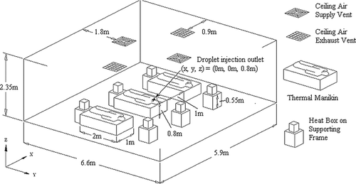
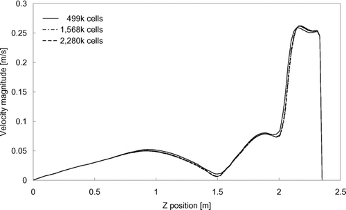
The dimensions of the computational geometry of the ward were adopted from a general hospital ward having dimensions of 5.9 × 6.6 × 2.35 m (W × L × H). Ventilation air was supplied from two four-way-spread type ceiling supply diffusers (0.6 m − 0.6 m) and returned through two ceiling exhaust vents (0.6 m × 0.6 m). Three beds, having the dimensions of 1 × 2 × 0.6 m (W × L × H) each, were placed with a 1m side-to-side gap between each bed. A 0.4 × 1.8 × 0.3 m (W × L × H) rectangular block was placed on each bed to represent a patient. Each block released 75 W of heat as adopted from the value for a sleeping person recommended by ASHRAE (Citation2004). A2 mm3 cube was placed on the top surface of the patient block in the middle bed as the injection inlet of expiratory droplets. The injection inlet was at the center of the ward, 0.8 m above ground. Heat releases from other equipment in the ward were simulated with six heating boxes (0.25 × 0.25 × 0.33 m, W × L × H each) placed on supporting frames of 0.55 m tall. The average per-floor-area internal heat density was 21 W/m2. A schematic diagram of the setting in the ward is shown in . The computational geometry of the ward was created using the GAMBIT (CitationFluent 2004) preprocessor. The grid convergence was tested with three mesh sizes by performing a set of airflow simulations using each grid. The three tested grid systems resulted in a total of 499 k (system 1), 1568 k (system 2) and 2280 k (system 3) meshes in the geometry, respectively. The mean velocity magnitude, turbulence kinetic energy and dissipation rate were selected as checking parameters along a vertical line near the center of the room. shows the distributions of the mean velocity magnitude obtained with different grid systems. Minor differences in the calculated results can be seen between the coarsest and the other two finer grids. The results obtained from the two finer grids are nearly indistinguishable. A similar monotonic converging trend was also observed in the turbulence parameters. To further analyze the convergence of these 3 grid systems, the grid convergence index (GCI) (CitationRoache 1998) was determined using the root-mean-square value of the relative error of the air velocity magnitude at 1000 selected points. GCI was calculated using the following formula:
Airflow Simulation
A multiphase numerical model similar to that employed by CitationChao and Wan (2006) and CitationWan et al. (2007) was adopted in this study. The governing equations of the carrier phase (air) were considered in the Eulerian frame (Navier-Stokes equations). Turbulence closure of the carrier phase was achieved by adopting the RNG k-ϵ turbulence model. Detailed description of the carrier phase equations are given in CitationChao and Wan (2006). Transient species transport model for water vapor was added to the Eulerian carrier phase models to represent the humidity in the air. Since there were heat sources in the ward (thermal manikins and heat boxes), the density of the air was set to follow a second-order polynomial function. The coefficients of the thermodynamic polynomial function were obtained by fitting the density / temperature data of air (CitationMcQuiston et al. 2005).
Near-Wall Treatment
Modeling of near-wall turbulence is of high importance in the current study since air turbulence can have critical influence on the transport of expiratory droplets through the boundary layer, which is a major deposition mechanism. To resolve the turbulent flow characteristics in the near-wall region, an enhanced two-layer wall treatment was adopted instead of the commonly employed standard “laws-of-the-wall” for near-wall turbulence modeling (CitationFluent 2005). Briefly, inside the viscosity-affected near-wall region (walldistance-based Reynolds no., Re y ≤ 200) the turbulent viscosity was calculated as (CitationChen and Patel 1988)
FIG. 3 Number percentages of deposited droplets relative to the total injection number. Test case: 11.6 ACH, vertical injection.
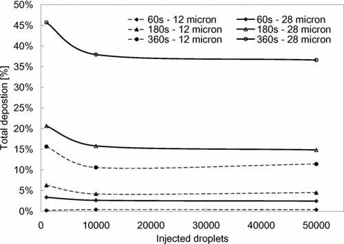
TABLE 1 Boundary conditions and parameter inputs for the numerical simulations
Particle Transport Simulation
The governing equation of the discrete phase (expiratory droplets) was a force balance equation in a Lagrangian frame of reference:
EXPERIMENTAL MEASUREMENTS OF DROPLET TRANSPORT
A. The Experimental Ward Geometry
To test the validity of the numerical simulations, a general hospital ward having the same dimensions as those in the computational geometry was used for the measurement of dispersion of expiratory droplets. The ward was ventilated by a ceiling-mixing-type ventilation system with two four-way-spread-type ceiling supply diffusers (0.6 m × 0.6 m). The air was returned through two ceiling extraction vents (0.6 m × 0.6 m). Measurements were conducted under the total supply airflow rate setting of 1060 m3/hr (11.6 ACH). The thermal conditions of the ward were maintained at 21.5°C, and 60% relative humidity. The same ward was used in another study under unoccupied conditions by CitationWan et al. (2007). Three beds, having the dimensions of 1 × 2 × 0.6 m (W × L × H) each, were placed with a 1 m side-to-side gap between each bed. A 1.8 m-tall thermal manikin was placed on each bed. The surface area of each thermal manikin was estimated to be about 1.9 m2. The thermal manikins were fabricated by coiling electric heating wires on fiber-glass models. The heating wires were evenly distributed throughout the manikins' bodies. On top of the heating wires, a layer of thin aluminum foil was wrapped to even out the heat distribution and to hold the wires in place. Six heating boxes (0.25 × 0.25 × 0.33 m, W × L × H each) were placed on supporting frames that were 0.55 m tall. The heating boxes were fabricated with thin aluminum sheets with a 100 W light bulb inside each of them.
Experimental Arrangements
Airflow at selected area in the ward was measured by particle image velocimetry (PIV) measurements to obtain input for the numerical simulations and for validation purpose. The size of each planar measurement field at each location was about 300 × 225 mm. Measurements were conducted at 11.6 ACH. Flow seeding was achieved by atomizing glycerin solution (75 wt% distilled water; 25 wt% pure glycerin (Acros Organics)) using a four-nozzle atomizer (LaVision Aerosol Generator), which produced seeds with a mean diameter of 0.25 μ m. The PIV images were taken and processed by an integrated PIV system (La Vision FlowMaster). More details regarding the PIV measurement can be found in CitationWan et al. (2007). Test droplets were produced using a self-developed droplet generator to simulate human coughs. Polydispersed test droplets were injected to the ward through the nozzle of the generator using compressed air and a ‘simulated saliva’ liquid solution. Size distribution of the generated droplets was characterized by an interferometric Mie imaging (IMI, La Vision SizingMaster IMI) system at the nozzle outlet. The droplet generator was calibrated to mimic the coughing size distribution reported by CitationDuguid (1946) with the peak initial droplet size at 12 μ m. Details regarding the construction of droplet generator and the size distribution can be found in CitationWan et al. (2007). The nozzle outlet of the droplet generator was mounted on the mouth of the “infector” (the thermal manikin lying in the middle bed), which was at the center of the ward, 0.8 m above the floor. Droplet injection was made in 2 directions: vertically upward and laterally towards the next bed. The ‘simulated saliva’ solution consisted of 12 g of sodium chloride mixed with 76 g of pure glycerin in 1.0 L of distilled water to mimic the nonvolatile content of human saliva. The non-volatile content contributed about 6% in volume to the simulated saliva solution. The compressed air flow rate for producing the injection was 0.4 L/s, which was approximately equivalent to exhaling a tidal volume of air of a normal human lung in each time of droplet injection (cough). At the beginning of each measurement, the injection was triggered by an electrical timer switch and maintained for 1 s. Droplet size distributions at a grid of pre-defined measurement points were measured for 360 s using the IMI system combined with a light-scattering aerosol spectrometer (GRIMM model 1.108). The IMI system measured droplets and droplet nuclei of 2 μ m and above and the aerosol spectrometer had a measurable size range of 0.3–20 μ m classified into 16 channels. The sampling airflow rate of the aerosol spectrometer was 0.02 L/s. More details regarding the measurement instruments can also be found in CitationChao and Wan (2006) and CitationWan et al. (2007). In the case of vertical injection, the measurement positions were distributed in a quarter of the ward at lateral distances (in both the x and y directions) of 0.15, 0.3, 0.6, 1.2, 1.8, and 2.4 m from the generator nozzle outlet. At each position, measurement points were distributed at heights of 0.1, 0.6, 1.1, 1.7, and 2.2 m. The measurement positions covered half of the ward in the case of lateral injection. Measurement points that were blocked by the beds or the heat boxes were skipped. The measured sizes of droplets and droplet nuclei were converted back to their original size by estimating the size shrinkage due to evaporation in the time period between the “cough” and the time of detection.
RESULTS AND DISCUSSION
Airflow Pattern and Validation of Expiratory Droplet Dispersion Results
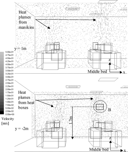
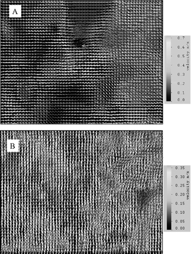
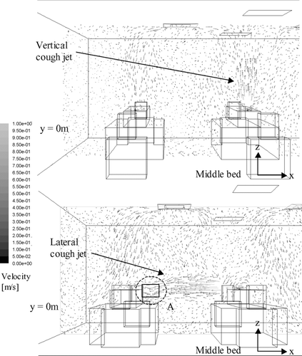
Airflow velocity vector plots on selected planes obtained by numerical simulations under 11.6 ACH are shown in and . shows the plots at the middle-plane (y = 0) of the ward during the production of the cough on half of the ward. Both the vertical and lateral injection cases are shown. In this plane, the supply air jets from the air diffusers and the cough jets were the major airflows. The figure shows that the vertical cough jet extended about 1 m above the injection point. With an initial velocity of 10 m/s, the vertical cough jet velocity at 1.7 m (0.9 m above the injection point) was about 0.5 m/s. In the lateral injection case, the cough jet reached the side of the manikin next bed at about 0.4 m/s. Similar velocity was also measured in the ward by PIV, as shown in . The cool supply air from the air diffusers created downward air currents of about 0.3–0.4 m/s above the manikins. Air velocities outside these major airflows were generally below 0.2 m/s. shows the airflow velocity vector plots at y = 1 m and y = −2 m on half of the ward, where the planes cut through the body of the manikins and the heat boxes respectively. Since these planes were away from the supply jets, the upward heat plumes generated by the manikins and the heat boxes were the major flow currents. The vector plots of the upward airflow velocities of the heat plums were about 0.3–0.4 m/s. The airflows outside the heat plume were generally below 0.2 m/s and the directions of the vectors were scattered. PIV measurements taken at the 1.7 m height (head level) above the heat box captured the generally upward airflow currents of around 0.3 m/s, as shown in . Comparison between the numerical airflow patterns and PIV measurements shows that the simulations were able to capture the major airflow characteristics in the ward. The simulated airflow patterns in the 6.0 ACH case generally followed a similar pattern described above. The supply air velocities at the air diffuser outlets and the downward air currents created by the cool supply air were about half of that observed in the 11.6 ACH case. Velocities of the cough jets and the heat plumes were of similar magnitude as that shown in and .
FIG. 4a Airflow velocity vector plot at the middle plane (y = 0) during injection for the vertical (above) and lateral (below) injection cases (11.6 ACH).
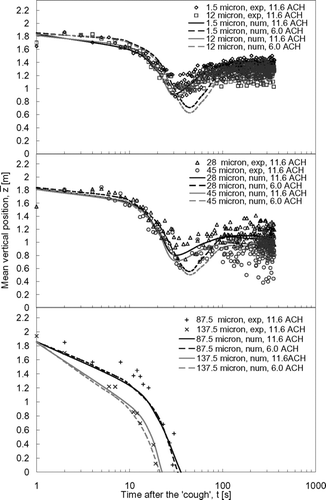
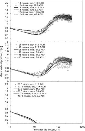
The droplet dispersion results predicted by numerical simulations were compared with the experimental results in , , , . The mean vertical positions of the expiratory droplets, z, for the vertical injection and lateral injection case are shown in and , respectively. The curves in the figures are the polynomial fits of the numerical prediction data (denoted by ‘num’ in the legend) and the symbols represent the experimental data (denoted by ‘exp’ in the legend) obtained in the ward. The sizes indicated in the legend are the initial droplet sizes. The numerical mean vertical position was the mean of vertical positions, z, of all airborne expiratory droplets of size l at time t obtained from the numerical particle tracking data. The experimental mean vertical position was determined by the following method. At a certain time, t, the number of expiratory droplet at each measurement point, p, was counted by the droplet measurement instruments and classified into different sizes, l. The vertical position of each measurement point, zp , was multiplied by the number of expiratory droplets counted at that point. Adding all these products of every measurement point together and dividing the sum by the total counted number of expiratory droplet, the mean vertical position at time t for expiratory droplets of size l could be calculated. This calculation can be expressed mathematically as:
Vertical Mixing Patterns
shows that the vertical “cough” jet pushed the expiratory droplets up for about a meter to an initial mean vertical position of about 1.8 m immediately after the injection. The mean vertical positions then started to drop due to the vertical mixing induced by the airflow. The effect of the droplet size on the vertical dispersion of the droplets has been discussed in our previous paper (CitationWan et al. 2007). Basically, there was not much change at the 11.6 ACH setting between this set of data and the data collected when the room was empty. Here the focus is on the effect of the airflow supply. At the weaker airflow supply rate (6.0 ACH), the drop in the mean vertical position induced by the airflow was slower and lasted for a longer time compared to the 11.6 ACH case. This suggests that, in the 6.0 ACH case, the expiratory droplets might stay longer in the area subjected to downward airflow currents, as shown in . This is related to the fact that lateral dispersion at low ACH was slower, causing the droplets to stay longer in the downward airflow zone. Further discussion will be addressed in the “Lateral dispersion patterns” section. The mean vertical positions of the expiratory droplets that were ≤45 μ m (the initial size) attained relatively stable values after about 100 s. The influence of the gravitational effect on expiratory droplets of different sizes can be seen by comparing the mean vertical positions longer times after the injection. As time went on, larger expiratory droplets tended to settle to lower positions under a weaker ventilation rate setting. For instance, at 360 s after the injection, the mean vertical position of the 1.5 μ m droplets was at about 1.4 m under the 11.6 ACH supply airflow rate setting. The mean vertical position of the 45 μ m droplets was at about 0.9 m under the same ventilation rate. Settling of larger expiratory droplets became more obvious in the 6.0 ACH case. The mean vertical positions of the 1.5 μ m droplets at 360 s were nearly the same as in the 11.6 ACH case but the mean vertical position of the 45 μ m droplets was dropped to about 0.8 m. This indicates that the heat plume effect from the heat sources, as shown in , may have compensated for the loss of the vertical mixing effect with a weaker ventilation rate for the smaller expiratory droplets. As the gravitational effect became more significant in larger expiratory droplets, the contribution of vertical mixing by heat plumes diminished relatively. The transport of very large droplets (≥87.5 μ m) was dominated by gravitational settling. These very large droplets continued to drop after the initial “coughing” injection had pushed them to about 1.8 m high. The time of remaining airborne was less than 36 s and 23 s for the 87.5 μ m and 137.5 μ m droplets, respectively. The change in the ventilation rate had no significant effect on the transport of these very large droplets.
With the ‘coughing’ injection produced in the lateral direction (), the expiratory droplets started at a mean vertical position of ∼ 0.8 m (the height of the droplet injection outlet). The mean vertical positions showed a slight drop in the next 10–20 s, suggesting that the majority of the expiratory droplets remained in low positions in the ward in this period. Similar to the case of vertical injection, the drop in the mean vertical positions was slower at smaller airflow supply rate settings. The mean vertical positions of the expiratory droplets gradually increased to levels that were similar to those observed in the vertical coughing cases after about 100 s. The mean vertical positions of the 1.5 μ m droplets were similar in the two ventilation rate settings but the mean vertical position at 6.0 ACH for the 45 μ m droplets was about 0.1 m lower than that in the 11.6 ACH case. The transport of very large droplets (≥87.5 μ m) was also dominated by the gravitational settling effect. Since the laterally produced cough did not push up these very large droplets, their airborne time was reduced to 13 s and 11 s for 87.5 μ m and 137.5 μ m droplets, respectively, which were much less than the corresponding values in the vertical coughing case.
Lateral Dispersion Patterns
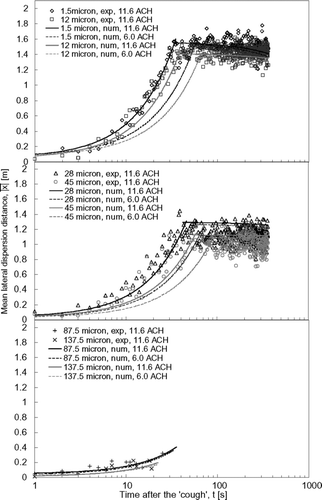
The origin of the y-axis in represents the middle plane of the room. As shown in , this was where the droplet injection point was located. |x| was calculated based on the absolute lateral distance between the droplets and the source point. Therefore, as a reference, in the perfectly mixed condition, |x| would be at the middle of a half of the room, i.e., 1.48 m. Since the lateral dispersion of the expiratory droplets with initial sizes up to 45 μ m exhibited two-stage behavior, i.e., the mean lateral dispersion distance increased rather rapidly in the early stage and became more stabilized in the later stage, the fitting curves of the numerical data were broken into two parts. As demonstrated by CitationWan et al. (2007) in the empty room setting, smaller expiratory droplets dispersed faster laterally compared to the larger droplets. A similar observation can be made in the current case under occupied conditions. Comparing the two supply airflow rate, the lateral dispersion rates were slower at smaller airflow supply rates but eventually the expiratory droplets reached similar mean lateral dispersion distances with both airflow supply rate settings. The 1.5 μ m droplets reached a mean lateral distance of about 1.5 m in 33 s in the 11.6 ACH case. The time taken for reaching a similar mean lateral distance in the 6.0 ACH case was lengthened to 56 s. For the 45 μ m droplets, the time taken for reaching a mean lateral distance of 1 m was 55 s and 87 s in the 11.6 ACH and 6.0 ACH cases, respectively. The slower lateral dispersion in the 6.0 ACH case could be the reason for the longer drop time after the injection as shown in . It took the droplets a longer time to leave the zone where the downward airflow current was strong and also, because of the slower lateral dispersion, the droplets stayed longer in this downward airflow zone and, thus, in , the minimum mean vertical position was found to be lower in the 6 ACH case compared with the 11.6 ACH case. Due to the very short airborne time, the mean lateral dispersion distances of the 87.5 μ m and 137.5 μ m droplets could only reach about 0.4 m and 0.2 m, respectively. The differences between the two supply airflow rates for this size range were insignificant.
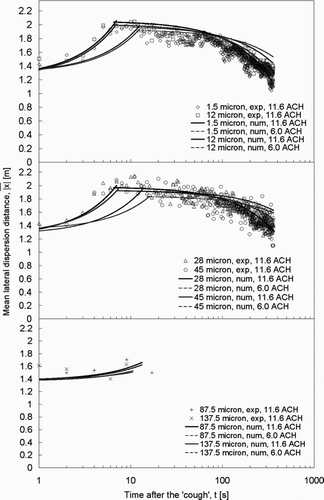
Comparing to , the lateral dispersion patterns of the expiratory droplets in the lateral injection case differed significantly from those obtained in the vertical injection case. Instead of being dispersed entirely by the ventilation airflow, as shown by the gradual increase in the mean lateral dispersion distances from zero in , the expiratory droplets were pushed abruptly by the initial “coughing” injection to a mean lateral distance of ∼ 1.3 m in the lateral injection case. This can be inferred from the lateral cough jet velocity plot shown in . Under the airflow supply rate of 11.6 ACH, the expiratory droplets continued to disperse to a maximum mean lateral distance of about 2 m in the next 6–7 seconds, reaching the breathing zone of the next patient. This indicates that many of the expiratory droplets accumulated in the further side on the half of the ward into which the cough jet was projected. As time moved on, the expiratory droplets continued to disperse throughout the room in the mixing air. The mean lateral dispersion distances started to decrease. By lowering the airflow supply rate to 6.0 ACH, the rate of lateral dispersion became slower. After the initial push by the injection to about 1.3 m, droplets of ≤45 μ m continued to disperse laterally to reach the maximum mean lateral distances in about 13 to 17 s. The maximum mean lateral distances were about 0.05–0.1 m less than the distance in the 11.6 ACH case. The slower rate of reduction in the mean lateral distance after reaching the maximum dispersion distance indicates that more expiratory droplets stayed near the side of the ward for longer times, due to the slower mixing effect by the 6.0 ACH airflow supply rate setting.
Deposition Characteristics
To compare the deposition behavior under different ventilation rate settings, deposition velocities of expiratory droplets ≤ 45 μ m in size were estimated from the numerical results. With the predicted depositions on all the surfaces in the entire computational geometry, the overall deposition velocity for the lth size of the expiratory droplets could be estimated using the following relation:
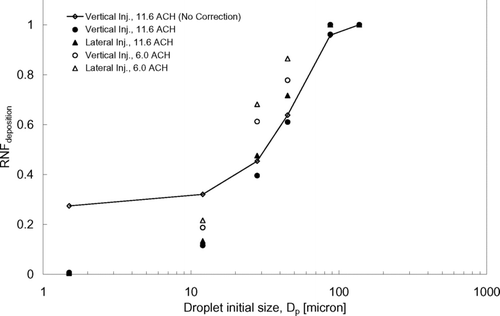
From , nearly all (above 95%) of the very large expiratory droplets (≥87.5 μ m) were lost by deposition. This means that gravitational settling was the dominant removal mechanism for this size range while, comparatively, the injection orientation and ventilation rate had insignificant effects. Some portions of the expiratory droplets ≤45 μ m in size were removed by air extraction. This suggests that this size range exhibited transport behavior favorable for dispersion via the airborne route, which concurs with the observations from the dispersion behaviors described in the previous section. The RNF deposition increased with the size of the expiratory droplets, indicating the increasing importance of gravitational settling with size. Comparing the two injection orientations, higher RNF deposition values were obtained in the lateral injection cases under the same airflow supply rate, which suggests that the expiratory droplets were subjected to more deposition losses when the cough was made laterally. The higher RNF deposition obtained at 6 ACH compared to at 11.6 ACH does not necessarily mean that there was more deposition at a weaker airflow supply. Since the results were obtained at 360s after the injection, the volume of air that was extracted in this time period would certainly be less with a lower airflow supply rate. To compare the deposition behavior due to different ventilation rate settings, deposition velocity should be used.
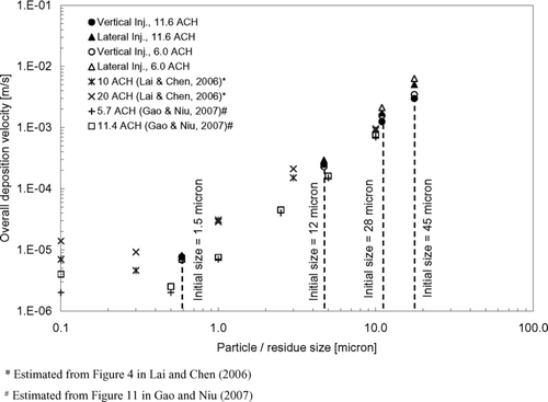
shows the estimated overall deposition velocities using Equation (Equation11). It can be seen that the change in the ventilation rate setting did not have a significant effect on the overall deposition velocities of the expiratory droplets. This may be because major depositions occurred on upward facing horizontal surfaces, on which gravitational settling played a relatively more significant role. Turbulent diffusion, a deposition mechanism that could be affected by the ventilation rate setting, became less significant compared to gravitational settling, especially after applying the near-wall correction. As shown by the RNF, coughing laterally led to more deposition of expiratory droplets compared to coughing vertically. This observation is also reflected in the overall deposition velocities shown in . The difference in the overall deposition velocity between the two injection cases became larger for bigger expiratory droplets. Compared to the vertical injection case, the overall deposition velocity in the lateral injection case increased slightly by around 10% for the 1.5 μ m droplets but it was nearly doubled for the 45 μ m droplets. Recalling the vertical mixing behavior described in the previous section, it has been shown that most of the expiratory droplets remained in the lower part of the room once they were introduced by coughing laterally. Many of the surfaces, especially the upward facing horizontal surfaces (e.g., the floor, manikins, beds, and other objects), are in the lower part of the room, favoring the deposition of the larger expiratory droplets. Deposition velocities reported by CitationLai and Chen (2006) and CitationGao and Niu (2007) were also plotted in for comparison. The modeling approach in CitationLai and Chen (2006) was very similar to the approach employed in the current study. CitationGao and Niu (2007) employed an Eulerian-based drift flux model and adopted the empirical model suggested by CitationLai and Nazaroff (2000) (the L & N model) for particle deposition. Since dry particles were simulated in both the studies by CitationLai and Chen (2006) and CitationGao and Niu (2007), results of the current study were plotted with respect to the residue size of the expiratory droplets to facilitate the comparison. The corresponding droplet initial sizes are indicated in the figure. It can be seen that the predicted overall deposition velocities in the current study agreed with the trend reported by CitationLai and Chen (2006) fairly well. Comparatively, the deposition velocities reported by CitationGao and Niu (2007) are lower by about an order of magnitude in the sub-micron size range. The difference becomes less in the super-micron range.
Modifying Equation (Equation11) for individual surface, k, into the following form, the deposition velocities for different types of surfaces were calculated:
FIG. 11 Deposition velocities of expiratory droplets with initial size = 1.5 μm (a); 12 μm (b); 28 μm (c); and 45 μm (d) for difference surfaces. (Continued)
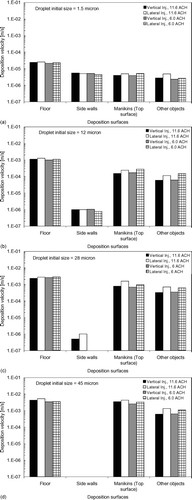
Experiments using fluorescent particles or dye are recommended to validate the predicted depositions on different surfaces in future studies. From , , , , it can be seen that upward-facing surfaces were the major deposition sites for all sizes of expiratory droplets as the deposition velocities for the floor were significantly higher than those for side walls and other objects. In Figures , , it is shown that the deposition velocities for the manikins (top surface) were about five times lower than those for the floor. This suggests that the heat plume generated above the heated manikins as well as the repelling force by thermophoresis greatly reduced the deposition of these small expiratory droplets. The effects of the heat plume and thermophoresis on repelling deposition was much reduced for larger droplets, as shown in . The deposition velocities of the 45 μ m droplets for the heated manikins (top surface) were similar to those for the unheated floor surface. Except for the side walls, the deposition velocities of larger droplets for all other surfaces were substantially higher than those of the 1.5 μ m droplets, indicating the dominance of gravitational settling in governing the deposition behavior on these surfaces. Deposition velocities for surfaces other than the side walls were higher in the lateral injection cases compared to the vertical injection cases. This indicates that lateral injection enhanced the deposition on these surfaces, which explains the higher RNF deposition and overall deposition velocities obtained in the lateral injection cases. Judging from these observations, the deposition velocities for the side walls decreases further while the deposition velocities for all other surfaces increases for larger expiratory droplets. The effects of the heat plumes and thermophoresis also become less significant and the difference in the deposition velocity between manikins (top surface) and the floor would diminish as the droplet size increases. The enhancement of deposition on upward facing surfaces by lateral injection compared to vertical injection becomes more significant for large droplets.
CONCLUSIONS
The transport and removal characteristics of expiratory droplets were investigated in a three-bed hospital ward with typical ceiling-mixing-type ventilation system. The effects of different airflow supply rates and “coughing” injection orientations were studied numerically using a Lagrangian-based particle-tracking model under two supply airflow rate settings (6.0 ACH and 11.6 ACH) and two injection orientations (vertically upward and laterally towards the next bed). The model was tested against experimental expiratory droplet dispersion data obtained in a real hospital ward. Reasonable agreement between the two sets of results was found. Between the two airflow supply rates, settling of larger expiratory droplets (28 and 45 μ m) became more obvious at the lower airflow supply rate, due to the reduced vertical mixing by the airflow. Smaller expiratory droplets (1.5 and 12 μ m) eventually attained similar vertical mixing in the two airflow supply rate settings. This may be because the thermal plumes generated from the heat sources in the ward compensated for the loss in vertical mixing effects by the reduced airflow supply on the smaller droplets. The rate of lateral dispersion became slower with the lower supply airflow rate for the 1.5–45 μ m droplets in both injection orientations. This suggests that the lateral dispersion behavior was dominated by the ventilation airflow and the effect of the thermal plume was relatively minor. Gravitation settling was the dominant transport mechanism for very large expiratory droplets (≥87.5 μ m). These very large droplets settled quickly with airborne times of less than 36 s among all simulated cases. The change in the airflow supply rate had an insignificant effect on the transport phenomena. This suggests that in terms of infection transmission, expiratory droplets of ≤45 μ m exhibit the possibility for being airborne pathogen carriers and their transport is affected by the room airflow.
Adopting near-wall correction for turbulence in the numerical simulations led to a reduction in the predicted deposition. The predicted fraction removed by deposition of the 1.5 μ m expiratory droplets was reduced by about 25%, compared to that obtained without the correction. The reduction became less for larger expiratory droplets. It indicates that the importance of turbulent diffusion, as one of the deposition mechanisms, was diminishing compared to gravitational settling for larger droplets. Heat plumes and thermophoresis led to a reduction in the deposition velocity by several times for droplets ≤12 μ m on heated upward-facing horizontal surfaces. The importance of gravitational settling in deposition increased for larger expiratory droplets. This was shown by the increase in the deposition velocity for upward-facing horizontal surfaces with larger droplet sizes. The repelling effect of heat plumes and thermophoresis became insignificant for larger expiratory droplets. The orientation of the “cough” jet was shown to have an impact on the deposition patterns. More deposition was predicted in the lateral injection case compared to the vertical injection case, especially for larger droplets. The overall deposition velocity for the 1.5 μ m droplets was slightly increased by about 10% but it was nearly doubled for the 45 μ m droplets compared to the vertical injection case. This was because the expiratory droplets remained in the lower part of the room, where many of the upward-facing horizontal surfaces were located, once they were introduced by coughing laterally. More than 95% of expiratory droplets ≥87.5 μ m were removed by deposition due to the dominance of gravitational settling. This suggests that pathogens carried in larger expiratory droplets may not be active in airborne disease transmission but they can be a significant contributor to other modes of transmission such as droplet mode or indirect contact through surfaces. The current study focuses on the physical transport of expiratory droplets which can be a basis for understanding the relationship between dose and exposure of pathogenic materials. Further studies are still required to understand the fate of microorganisms and how the transport of pathogenic materials affects the exposure and infection risk in order to form a more comprehensive picture on this issue.
Acknowledgments
This research was financially supported by Research Grants Council, The Government of Hong Kong S.A.R through grant number RGC 611506. Support and clinical advice provided by Dr. W.C. Yu from Princess Margaret Hospital, Hong Kong, on the hospital ward experiments were appreciated.
REFERENCES
- ASHRAE . 2004 . ANSI/ASHRAE Standard 55-2004 Thermal Environmental Conditions for Human Occupancy , Atlanta : American Society of Heating, Refrigerating and Air-conditioning Engineers .
- Bouilly , J. , Limam , K. , Béghein , C. and Allard , F. 2005 . Effect of Ventilation Strategies on Particle Decay Rate Indoors: An Experimental and Modelling Study . Atmos. Environ. , 39 : 4885 – 4892 .
- Chang , T. J. , Hsieh , Y. F. and Kao , H. M. 2006 . Numerical Investigation of Airflow Pattern and Particulate Matter Transport in Naturally Ventilated Multi-room Buildings . Indoor Air , 16 : 136 – 152 .
- Chao , C. Y. H. and Wan , M. P. 2006 . A Study of the Dispersion of Expiratory Aerosols in Uni-directional Downward and Ceiling-return Type Airflows Using Multiphase Approach . Indoor Air , 16 ( 4 ) : 296 – 312 .
- Chen , H. C. and Patel , V. C. 1988 . Near-Wall Turbulence Models for Complex Flows Including Separation . AIAA J. , 26 ( 6 ) : 641 – 648 .
- Cole , E. C. and Cook , C. E. 1998 . Characterization of Infectious Aerosols in Health Care Facilities: An Aid to Effective Engineering Controls and Preventive Strategies . Am. J. of Infect. Control. , 26 : 453 – 464 .
- Duguid , J. P. 1946 . The Size and the Duration of Air-carriage of Respiratory Droplets and Droplet-nuclei . J. Hyg. , 44 : 471 – 479 .
- Fluent . 2004 . GAMBIT 2.2 User's Guide , Lebanon : Fluent Inc . Fluent (2005) Fluent 6.2 User's Guide Fluent Inc, Lebanon
- Gao , N. P. and Niu , J. L. 2007 . Modeling Particle Dispersion and Deposition in Indoor Environments . Atmos. Environ. , 41 : 3862 – 3876 .
- Garner , J. S. 1996 . Guideline for Isolation Precautions in Hospitals. The Hospital Infection Control Practices Advisory Committee . Infect. Control Hosp. Epidemiol. , 17 : 53 – 80 .
- Kallio , G. A. and Reeks , M. W. 1989 . A Numerical Simulation of Particle Deposition in Turbulent Boundary Layers . Aerosol Sci. Technol. , 15 ( 3 ) : 433 – 446 .
- Hu , S. C. and Hsiao , T. R. 2005 . Particle Dynamics in a Front-Opening Unified Pod/Load Port Unit Minienvironment in the Presence of a 300mm Wafer in Various Positions . Aerosol Sci. Technol. , 39 : 185 – 195 .
- Huang , C. B. and Lin , C. S. 2006 . Modeling of Aerosol Dynamics along a Vertical Flat Plate . Build. Environ. , 41 : 568 – 577 .
- Lai , A. C. K. and Chen , F. 2006 . Modeling Particle Deposition and Distribution in a Chamber with a Two-equation Reynolds-averaged Navier-Stokes model . J. Aerosol Sci. , 37 : 1770 – 1780 .
- Lai , A. C. K. and Cheng , Y. C. 2007 . Study of Expiratory Droplet Dispersion and Transport using a New Eulerian Modeling Approach . Atmos. Environ. , 41 ( 35 ) : 7473 – 7484 .
- Lai , A. C. K. and Nazaroff , W. W. 2000 . Modeling Indoor Particle Deposition from Turbulent Flow onto Smooth Surfaces . J. Aerosol Sci. , 31 ( 4 ) : 463 – 476 .
- Lai , A. C. K. and Nazaroff , W. W. 2005 . Supermicron Particle Deposition from Turbulent Chamber Flow onto Smooth and Rough Vertical Surfaces . Atmos. Environ. , 39 : 4893 – 4900 .
- Li , A. and Ahmadi , G. 1992 . Dispersion and Deposition of Spherical Particles from Point Sources in a Turbulent Channel Flow . Aerosol Sci. Technol. , 16 : 209 – 226 .
- Li , Y. , Leung , G. M. , Tang , J. W. , Yang , X. , Chao , C. Y. H. , Lin , J. Z. , Lu , J. W. , Nielsen , P. V. , Niu , J. , Qian , H. , Sleigh , A. C. , Su , H-J. J. , Sundell , J. , Wang , T. W. and Yuen , P. L. 2007 . Role of Ventilation in Airborne Transmission of Infectious agents in the Built Environment—A Multidisciplinary Systematic Review . Indoor Air , 17 : 2 – 18 .
- Matida , E. A. , Finlay , W. H. , Lange , C. F. and Grgic , B. 2004 . Improved Numerical Simulation of Aerosol Deposition in an Idealized Mouth-Throat . J. Aerosol Sci. , 35 : 1 – 19 .
- McQuiston , F. C. , Parker , J. D. and Spitler , J. D. 2005 . Heating, Ventilating, and Air Conditioning: Analysis and Design , New York : Wiley .
- Qian , H. , Li , Y. , Nielsen , P. V. , Hyldgaard , C. E. , Wong , T. W. and Chwang , A. T. Y. 2006 . Dispersion of Exhaled Droplet Nuclei in a Two-bed Hospital Ward with Three Different Ventilation Systems . Indoor Air , 16 : 111 – 128 .
- Qian , H. , Li , Y. , Nielsen , P. V. and Hyldgaard , C. E. 2008 . Dispersion of Exhalation Pollutants in a Two-bed Hospital Ward with a Downward Ventilation System . Build. Environ. , 43 ( 3 ) : 344 – 354 .
- Roache , P. J. 1998 . Verification of Codes and Calculations . AIAA J. , 36 ( 5 ) : 696 – 702 .
- Schneider , T. , Kildesø , J. and Breum , N. O. 1999 . A Two Compartment Model for Determining the Contribution of Sources, Surface Deposition and Resuspension to Air and Surface Dust Concentration Levels in Occupied Rooms . Build. Environ. , 34 : 583 – 595 .
- Talbot , L. , Cheng , R. K. , Scheffer , R. W. and Willis , D. R. 1980 . Thermophoresis of Particles in a Heated Boundary Layer . J. Fluid Mech. , 101 ( 4 ) : 737 – 758 .
- Wan , M. P. and Chao , C. Y. H. 2007 . Transport Characteristics of Expiratory Droplets and Droplet Nuclei in Indoor Environments with Different Ventilation Air Flow Patterns . J. Biomech. Eng., T-ASME. , 129 ( 3 ) : 341 – 353 .
- Wan , M. P. , Chao , C. Y. H. , Ng , Y. D. , Sze To , G. N. and Yu , W. C. 2007 . Dispersion of Expiratory Droplets in a General Hospital Ward with Ceiling Mixing Type Mechanical Ventilation System . Aerosol Sci. Technol. , 41 : 244 – 258 .
- Wang , Y. and James , P. W. 1999 . On the Effect of Anisotropy on the Turbulent Dispersion and Deposition of Small Particles . Int. J. Multiphase Flow , 25 : 551 – 558 .
- Zhang , Z. , Kleinstreuer , C. , Donohue , J. F. and Kim , C. S. 2005 . Comparison of Micro- and Nano-size Particle Depositions in a Human Upper Airway Model . J. Aerosol Sci. , 36 : 211 – 233 .
