Abstract
The basic equations governing the responses of single and tandem differential mobility analyzer (DMA) systems are summarized. Particle diffusion within the DMA resulting in broadening of the transfer function is included in this analysis. For tandem DMA (TDMA) work, a given particle diameter exiting the first DMA is modeled in the following conditioner as growing into a multi-modal lognormal distribution before entering the second DMA. Approximations and solution techniques for both single and tandem DMA systems are discussed. A new lognormal approximation to the DMA transfer function is introduced leading to a simple lognormal form for the TDMA response function. The maximum absolute error of the transfer function is 0.10 at 200 nm in the range plus or minus one and a half standard deviations of the lognormal fit. It is 0.035 at 3 nm in the range plus or minus two standard deviations of the lognormal fit. The maximum fractional error in the calculated TDMA response is no more than 0.08 at 200 nm and 3 nm in the range plus or minus one standard deviation of the lognormal fit.
DMA NOMENCLATURE
| a* | = |
= (− dln Z p /dln D p ) | D p * |
| b | = |
radial classifier plate separation |
| D | = |
particle diffusion coefficient |
| [Dtilde] | = |
4π LD/(Q m + Q c ) dimensionless particle diffusivity |
| D p | = |
particle diameter |
| D p * | = |
particle diameter associated with Z p * |
| [Dtilde] p | = |
= D p /D p * dimensionless particle diameter |
| [Dtilde] pg | = |
geometric mean of lognormal Ω in [Dtilde] p space |
| erf(x) | = |
error function |
| f c | = |
aerosol charge fraction |
| f cond | = |
aerosol conditioner function |
| f 0cond | = |
fraction of conditioned aerosol in a mode |
| G cond | = |
geometric mean diameter growth factor of conditioned aerosol mode |
| G DMA | = |
dimensionless classifier geometry and flow factor |
| L | = |
axial classifier inlet and outlet slit separation |
| M 0 | = |
zeroeth moment of transfer function |
| M Dg0 | = |
zeroeth moment of lognormal Ω in [Dtilde] p space |
| M Zg0 | = |
zeroeth moment of lognormal Ω in [Ztilde] p space |
| dN/dlog Dp | = |
aerosol size distribution function |
| N 1 | = |
measured aerosol concentration downstream of DMA1 |
| N 2 | = |
measured aerosol concentration downstream of DMA2 |
| Q a | = |
aerosol inlet flow rate |
| Q c | = |
clean sheath air inlet flow rate |
| Q m | = |
main excess air outlet flow rate |
| Q s | = |
aerosol sampling outlet flow rate |
| R 1 | = |
outer radius of axial classifier center rod |
| R 2 | = |
inner radius of axial classifier housing |
| R in | = |
aerosol inlet radius of radial classifier |
| R out | = |
aerosol outlet radius of radial classifier |
| V | = |
voltage applied to classifier |
| Z p | = |
particle electric mobility |
| Z p * | = |
transfer function centroid electric mobility |
| Δ Z p | = |
transfer function base half width |
| [Ztilde] p | = |
= Z p /Z p * dimensionless particle mobility |
| [Ztilde] pg | = |
geometric mean of lognormal Ω in [Ztilde] p space |
| Greek Letters | = | |
| β | = |
= (Q s + Q a )/(Q m + Q c ) |
| δ | = |
= (Q s − Q a )/(Q s + Q a ) |
| ϵ (x) | = |
= x ·erf(x) +e − x 2 /√π |
| Δ φ | = |
change in electric flux function from aerosol inlet to outlet |
| η CPC | = |
CPC counting efficiency |
| σ | = |
√G DMA [Dtilde] dimensionless classifier diffusion parameter |
| σ* | = |
σ evaluated at centroid mobility Z p * |
| σ cond | = |
geometric standard deviation of growth factor of conditioned aerosol mode |
| σ Dg | = |
geometric standard deviation of lognormal Ω in [Dtilde] p space |
| σ Zg | = |
geometric standard deviation of lognormal Ω in [Ztilde] p space |
| Ω | = |
classifier transfer function |
| Ω d | = |
diffusing transfer function |
| Ω nd | = |
non-diffusing transfer function |
INTRODUCTION
The Differential Mobility Analyzer (DMA) was introduced more than three decades ago (CitationHewitt 1957; CitationKnutson and Whitby 1975) and was soon used routinely as a sizing standard for submicron gasborne particles (CitationLiu and Pui 1974). Soon thereafter, CitationKnutson (1976) established the principles for using DMAs to measure submicron aerosol size distributions. Numerous refinements in instrumentation and data analysis methods have increased the time resolution and range of sizes that can be measured by electrical mobility classification, and this is now the most commonly used technique for measuring size distributions of 3–100 nm particles. Several commercial instrument systems complete with software are currently available for measuring aerosol mobility distributions. These instruments are referred to as Scanning Mobility Particle Sizers (SMPS; CitationWang and Flagan 1990). The data inversion is based on the approximation that the aerosol exiting the DMA is “monodisperse” relative to any other particle size-dependent parameter in the system. The end user of such a package no longer needs to know the actual workings of the DMA or the software. All that is required is to input the start and stop voltages (i.e., diameters), number of bins (i.e., resolution) and scan time. When the scan is complete the software outputs the size distribution as well as total number, surface, and volume. In most cases, the data represent the true distributions quite well.
The configuration of two DMAs in series, called the Tandem Differential Mobility Analyzer (TDMA) (CitationRader and McMurry 1986), was first exploited by Liu et al. (1978), McMurry et al. (1983), and Rader et al (1987) to measure particle growth/shrinkage due to hygroscopicity, gas phase reaction, and evaporation, respectively. Hygroscopicity TDMA (HTDMA) measurements of water uptake by atmospheric aerosols was recently reviewed by CitationSwietlicki et al. (2008); observations from more than 100 articles on this topic were summarized in this article. TDMA systems can also be used to study the effects of other processes on mobility size including heating (Volatility TDMA; VTDMA) (CitationKuhn et al. 2005; CitationOrsini et al. 1999; CitationPhilippin et al. 2004; CitationSakurai et al. 2003a; CitationSakurai et al. 2003b) and chemical reactions (Reactivity TDMA; RTDMA) (CitationGupta et al. 1995; CitationHiggins et al. 2002; Citation2003; CitationLiao et al. 2006; CitationLiao and Roberts 2006; CitationNienow et al. 2004). TDMA systems can also be used to evaluate DMA Transfer Functions (CitationFissan et al. 1996; CitationHummes et al. 1996; CitationLi et al. 2006; CitationStolzenburg and McMurry 1988; CitationStratmann et al. 1997).
In TDMA experiments, the raw data consists of number concentration downstream of the second DMA versus voltage on the second DMA. Growth factors can be determined fairly accurately from peak locations in these data. However, to make full use of the power of the TDMA, CitationRader and McMurry (1986) developed the exact equations governing the response of the system and solved them to obtain 1% precision in particle growth factors. An alternative approach for analyzing TDMA data was recently described by CitationCubison et al. (2005), which involved adapting the optimal estimation method of Rogers (1976, 1990). Some researchers have used SMPS software to reduce TDMA data. Again, this will yield fairly accurate peak locations and growth factors. However, the approximation made in SMPS analyses that the aerosol size distribution entering DMA2 is constant over the DMA2 mobility window is not valid for TDMA measurements. This approximation will lead to errors in values of the retrieved size distributions, which will be significantly wider than the true values.
This work provides a summary of the important equations governing the responses of the single DMA and TDMA systems including diffusional broadening of the DMA transfer function. The article includes a summary of our earlier work that has been widely used but not yet published (CitationStolzenburg 1988; CitationStolzenburg and McMurry 1988) as well as some significant new extensions to this work. For TDMA work, the output of the aerosol conditioner is modeled as a multi-modal lognormal distribution for a given input particle diameter. A new lognormal approximation to the DMA transfer function is introduced greatly simplifying the calculation of the diffusing transfer function. It also leads to a simple lognormal form for the calculated TDMA response function.
ANALYSIS FOR DIFFUSING AND NON-DIFFUSING DMA TRANSFER FUNCTIONS
The DMA transfer function, Ω, is defined as the probability of a particle of a given size successfully traversing the classifier (CitationKnutson and Whitby 1975). Specifically, it is the probability of the particle, starting at the aerosol entrance of the classification zone, reaching the aerosol exit. Losses in the inlet and outlet zones outside the classification zone are not included in Ω.
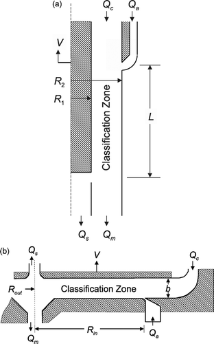
A schematic of an axial flow DMA is shown in . R 1 and R 2 are the inner and outer radii of the annular classification zone. L is the axial length between the midpoints of the aerosol inlet and outlet slits. Q a and Q s are the aerosol inlet and outlet flows; and Q c and Q m are the entering particle-free and exiting particle-laden sheath flows. The voltage, V, applied to the center rod is used to select particle size.
A schematic of a radial flow DMA (CitationZhang et al. 1995) is shown in . R in is the midpoint of the aerosol inlet slit, R out = 0Footnote 1 is the radius associated with the outlet flow and b is the distance between the plates. Q a , Q s , Q c , and Q m are the same as for the axial flow DMA and V is the voltage applied to the top plate.
Non-Diffusing Transfer Function
Non-diffusing particles follow particle streamlines (analogous to fluid streamlines, CitationKnutson and Whitby [1975]). When plotted against electric mobility, Z p , the transfer function, Ω nd , is triangular (or trapezoidal for unequal aerosol flows) with centroid mobility, Z p *, equal to
For the axial flow DMA, the change in the electrical flux from the aerosol inlet to the outlet is:
The rest of the analysis applies to both geometries of the DMA.
Particle diameter, D p , is related to Z p via
The non-diffusing transfer function can now be written as (CitationKnutson and Whitby 1975)
The dimensionless form of the non-diffusing transfer function, Ω nd , is plotted in .
Diffusing Transfer Function
To a good approximation diffusing particles spread in an ever-expanding Gaussian cross-stream profile about the corresponding non-diffusing particle streamline (CitationStolzenburg 1988), as shown in . At the aerosol exit the final standard deviation, σ, of this profile in non-dimensional form is given by
FIG. 3 Schematic of axial flow DMA showing non-diffusing particle streamline (a) and Gaussian cross-stream probability distributions (b) of diffusing particles.

The diffusing transfer function, Ω d , plotted in can now be given in non-dimensional form as (CitationStolzenburg 1988; Eq. Equation2.69)
Moments of the Transfer Function
For both diffusing and non-diffusing particles. (CitationStolzenburg 1988; Eqs. Equation2.88–2.91) the zeroeth moment of Ω is
The mean, E, and standard deviation, S, of Ω about the centroid, [Ztilde] p = 1, are given by
Integrated DMA Response Function
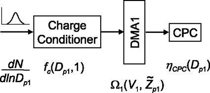
The typical instrument configuration involving a single DMA is shown in . This system measures an unknown size distribution, dN/dln Dp 1, by passing the aerosol through a charge conditioner, a DMA and then into a detector such as a condensation particle counter (CPC). The DMA is characterized by its transfer function, Ω1 (V 1, [Ztilde] p1), and the CPC by its detection efficiency, η CPC (D p1). The charge conditioner is characterized by the charge fraction f c (Z p1,n) = f c (D p1,n , n) where n is the number of charges on the particle, Z p1 is the particle electric mobility and D p1,n is the particle diameter associated with mobility Z p1 and n charges.
FIG. 5 Typical instrument configuration involving a single DMA showing entering size distribution, dN/dln D p1, charge conditioner, DMA and condensation particle counter and their associated characterization functions.
Raw data from this system is of the form (CitationKnutson 1976)
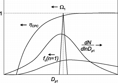
In most cases, the variations in η CPC (D p1), f c (D p1,1) and dN/dln D p1 are relatively small across the non-zero width of Ω1 (). Under these conditions the integrated response function can be approximated as (CitationKnutson 1976)
FIG. 6 Typical shapes of functions in the integrand of the integrated response for a single DMA system showing that variations within the non-zero width of the transfer function, Ω1, are small for all other functions.
To a good approximation over a sufficiently narrow range of sizes particle diameter and mobility can be related as
This is the standard accepted method for recovering the size distribution from a single DMA configuration. Equation (Equation27) is an approximation that is only accurate when the relative variation of the product (dN/dln D p1) · f c (D p1,1) · η CPC (D p1) is small across the non-zero width of the transfer function.
Integrated TDMA Response Function
The basic TDMA configuration is shown in . It consists of a bipolar charge conditioner with charge fraction f c (D p1,1), a first DMA with transfer function Ω1 (V 1, [Ztilde] p1), an aerosol conditioner, a second DMA with transfer function Ω2 (V 2, [Ztilde] p2) and a CPC with detection efficiency η CPC (D p2). The aerosol conditioner is characterized by f cond (D p2,D p1) which gives the normalized distribution of the final size, D p2, given an initial size, D p1. Appendix B presents the case in which f cond (D p2,D p1) can be characterized by a multi-modal lognormal distribution.
FIG. 7 Typical instrument configuration involving tandem DMAs showing entering size distribution, dN/dln D p1, bipolar charge conditioner, first DMA, aerosol conditioner, second DMA, and CPC and their associated characterization functions.

The integrated response, N 2 (V 2, V 1), for the TDMA system is given by (CitationRader and McMurry 1986)
FIG. 8 Typical shapes of functions in the integrand of the integrated response for TDMA system showing that variations within the non-zero width of the product of the transfer functions, Ω1 · Ω2, are small for all other functions.
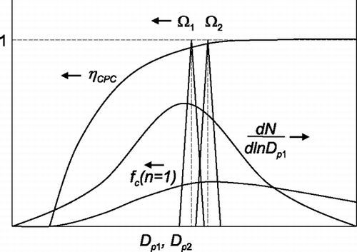
Using Equation (Equation21), Equation (Equation29) can be rewritten in terms of dimensionless diameters as
This can then be put in a more useful form in which the unknown entering size distribution function is eliminated using Equation (Equation27)
In most TDMA experiments, N 1 and N 2 are measured, Ω1 and Ω2 are known from theory and the objective is to determine the unknown aerosol conditioner characterization function, f cond (D p2,D p1). This can be done using a search routine to find values for the adjustable parameters of f cond (D p2,D p1) to optimize the fit of the calculated responses from Equation (Equation31) to the measured responses.
ANALYSIS FOR LOGNORMAL APPROXIMATION OF DMA TRANSFER FUNCTIONS
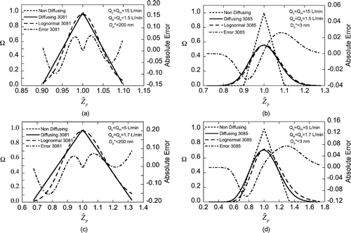
For an ideal DMA and non-diffusing particles the transfer function can be calculated exactly and is triangular in shape (Equation [Equation7]; CitationKnutson and Whitby 1975). CitationStolzenburg (1988) has derived an approximation to the transfer function for diffusing particles (Equation [Equation13]). The result is roughly Gaussian in shape but the calculation requires evaluation of cumbersome error functions. In this section we present a lognormal approximation to the DMA transfer function that is able to closely approximate either form and is easy to calculate.
Lognormal Transfer Function
The DMA transfer function (both diffusing and non-diffusing) can be approximated quite well by a lognormal function. For values of [Ztilde] p close to 1, the approximation that allows the DMA transfer function to be expressed as a lognormal distribution is simply
The lognormal approximation to the transfer function in dimensionless mobility space is then given by
Using Equations (Equation20) and (C.4) the transfer function in dimensionless diameter space is derived from Equation (Equation33) as
FIG. 9 Transfer functions for TSI 3081 and 3085 axial flow DMAs with different sheath and aerosol flows and voltage settings corresponding to 200 nm and 3 nm, respectively. Absolute error of lognormal transfer function is with respect to diffusing transfer function. The non-diffusing and diffusing transfer functions for the TSI 3081 at 200 nm are virtually indistinguishable.
Integrated DMA Response Function
Applying Equations (Equation21) and (Equation35) to the integrated single DMA response function in Equation (Equation25) yields
Integrated TDMA Response Function
The general integrated TDMA response function is given in Equation (Equation30). Assuming a unimodal lognormal conditioner function and applying Equations (EquationB.2), (EquationC.1), and (Equation35).
Applying Equations (EquationC.2), (EquationC.3), and (EquationC.6) yields
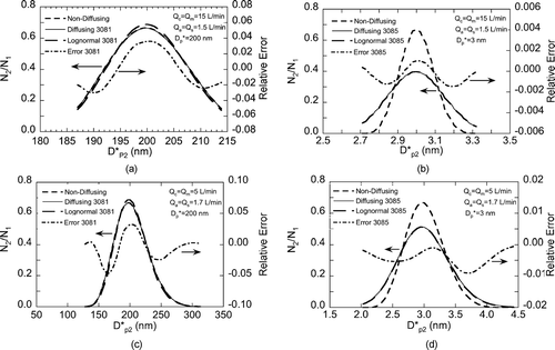
FIG. 10 TDMA responses with no conditioner for pairs of TSI 3081 and 3085 axial flow DMAs with different sheath and aerosol flows and DMA1 voltage settings corresponding to 200 nm and 3 nm, respectively. The relative error is the difference of the lognormal response and the diffusing response divided by the peak diffusing response. The non-diffusing and diffusing responses for the TSI 3081 at 200 nm are virtually indistinguishable as are the diffusing and lognormal responses for the TSI 3085 at 3 nm.
CONCLUSIONS
The basic equations governing the responses of single and tandem differential mobility analyzer (DMA) systems have been summarized. In most cases, single DMA integrated response data can be inverted using the simple, closed-form “monodisperse” approximation. This same approximation can only be used to partially simplify the TDMA integrated response equation and does not result in a closed-form solution. Instead, a best-fit search procedure must be used to determine the values of adjustable parameters in the aerosol conditioner function. Use of SMPS software on TDMA data, while easy and accurate to within a few percent, is not valid and does not allow access to the full power of the TDMA configuration, that is, less than one percent precision and information on the spread of the growth factor distribution.
A new lognormal approximation to the DMA transfer function fits the diffusing transfer function quite well and greatly simplifies the calculations. When this is combined for tandem DMA work with a lognormal aerosol conditioner function it leads to a simple lognormal form for the TDMA response function which can be readily inverted. The maximum fractional error in the TDMA response calculated from the lognormal transfer function is no more than 0.08 at 200 nm and 3 nm. The lognormal approximation could be used in a TDMA data inversion procedure to properly account for diffusional broadening of the DMA transfer function.
APPENDIX A: EVALUATION OF GEOMETRIC FACTOR G DMA
The geometric factor G DMA is the non-dimensionalized integral of v 2 r 2 dt where v is particle velocity, r is radial position and t is time (CitationStolzenburg [1988]; Appendices B and C). The integral is along the non-diffusing particle streamline of the centroid mobility of the transfer function from the aerosol entrance plane to the exit plane. It can be expressed as:
APPENDIX B: LOGNORMAL DISPERSION
A useful case to be considered here is when the aerosol conditioner function can be represented as a multi-modal lognormal distribution
One possible physical description for this situation is an aerosol for which there are several distinct types, each with a distribution of properties. Each particle type would correspond to one of the modes of the growth model with a lognormal distribution of properties. For the case in which a particle type has uniform properties, σ cond = 1, and no size change, G cond = 1, the corresponding term in Equation (EquationB.1) reduces to f 0cond .
Typically, the parameters f 0cond , G cond and σ cond are not known, where for simplicity only the unimodal case is considered here. Best fit values for these parameters can be determined by fitting calculated integrated responses N 2 to the corresponding measurements. The physically meaningful ranges for these fit parameters are
APPENDIX C: LOGNORMAL PROPERTIES
To facilitate the derivations in the main text a shorthand notation for the lognormal distribution is introduced as follows
The integral of the lognormal distribution is just unity
Acknowledgments
We gratefully acknowledge the assistance of Mr. Chongai Kuang, who proofread the manuscript and checked all equations. This research was supported, in part, by the Office of Science (BER), U.S. Department of Energy, grant DE-FG-02-05ER63997.
Notes
1 As with the axial flow DMA and L, R in and R out are defined according to the change in electric flux function from inlet to outlet. The flux function at each of these is equal to the asymptotic value approached deep within the inlet or outlet. For the inlet R in is half way between the walls of the inlet slit. For the outlet R out is on the axis of the exit tube. Hence, R out = 0.
REFERENCES
- Cubison , M. J. , Coe , H. and Gysel , M. 2005 . A Modified Hygroscopic Tandem DMA and a Data Retrieval Method Based on Optimal Estimation . J. Aerosol Sci , 36 : 846 – 865 .
- Fissan , H. , Hummes , D. , Stratmann , F. , Buscher , P. , Neumann , S. , Pui , D. Y. H. and Chen , D. 1996 . Experimental Comparison of Four Differential Mobility Analyzers for Nanometer Aerosol Measurements . Aerosol Sci. Technol. , 24 : 1 – 13 .
- Gupta , A. , Tang , D. and McMurry , P. H. 1995 . Growth of Monodisperse, Submicron Aerosol Particles Exposed to SO2, H2O2, and NH3 . J. Atmos. Chem. , 20 : 117 – 139 .
- Hatch , T. and Choate , S. P. 1929 . Statistical Distribution of the Size Properties of Non-Uniform Particulate Substances . J. Franklin Institute , 207 : 369 – 387 .
- Hewitt , G. S. 1957 . The Charging of Small Particles for Electrostatic Precipitation . Trans. Am. Inst. Engrs. , 76 : 300
- Higgins , K. J. , Jung , H. J. , Kittelson , D. B. , Roberts , J. T. and Zachariah , M. R. 2002 . Size-Selected Nanoparticle Chemistry: Kinetics of Soot Oxidation . J. Phys. Chem. A , 106 : 96 – 103 .
- Higgins , K. J. , Jung , H. J. , Kittelson , D. B. , Roberts , J. T. and Zachariah , M. R. 2003 . Kinetics of Diesel Nanoparticle Oxidation . Environ. Sci. Technol. , 37 : 1949 – 1954 .
- Hummes , D. , Stratmann , F. , Neumann , S. and Fissan , H. 1996 . Experimental Determination of the Transfer Function of a Differential Mobility Analyzer (DMA) in the Nanometer Size Range . Particle & Particle Systems Characterization , 13 : 327 – 332 .
- Knutson , E. O. 1976 . “ Extended Electric Mobility Method for Measuring Aerosol Particle Size and Concentration ” . In Fine Particles: Aerosol generation, measurement, sampling, and analysis , Edited by: Liu , B. Y. H. 739 – 762 . New York : Academic Press .
- Knutson , E. O. and Whitby , K. T. 1975 . Aerosol Classification by Electric Mobility: Apparatus, Theory, and Application . J. Aerosol Sci. , 6 : 443 – 451 .
- Kuhn , T. , Biswas , S. and Sioutas , C. 2005 . Diurnal and Seasonal Characteristics of Particle Volatility and Chemical Composition in the Vicinity of a Light-Duty Vehicle Freeway . Atmos. Environ. , 39 : 7154 – 7166 .
- Li , W. L. , Li , L. and Chen , D. R. 2006 . Technical Note: A New Deconvolution Scheme for the Retrieval of True DMA Transfer Function from Tandem DMA Data . Aerosol Sci. Technol. , 40 : 1052 – 1057 .
- Liao , Y. C. , Nienow , A. M. and Roberts , J. T. 2006 . Surface Chemistry of Aerosolized Nanoparticles: Thermal Oxidation of Silicon . J. Phys. Chem. B , 110 : 6190 – 6197 .
- Liao , Y. C. and Roberts , J. T. 2006 . Self-Assembly of Organic Monolayers on Aerosolized Silicon Nanoparticles . J. Amer. Chem. Soc. , 128 : 9061 – 9065 .
- Liu , B. Y. H. and Pui , D. Y. H. 1974 . A Submicron Aerosol Standard and the Primary, Absolute Calibration of the Condensation Nuclei Counter . J. Colloid Interface Sci. , 47 : 155 – 171 .
- Nienow , A. , Roberts , J. T. and Ajo , H. 2004 . Oxidation of Size-Selected Soot Nanoparticles . Abstracts of Papers of the American Chemical Society , 228 : U226 – U226 .
- Orsini , D. A. , Wiedensohler , A. and Stratmann , F. 1999 . A New Volatility Tandem Differential Mobility Analyzer to Measure the Volatile Sulfuric Acid Fraction . J. Atmos. Oceanic Technol. , 16 : 760 – 772 .
- Philippin , S. , Wiedensohler , A. and Stratmann , F. 2004 . Measurements of Non-Volatile Fractions of Pollution Aerosols with an Eight-Tube Volatility Tandem Differential Mobility Analyzer (VTDMA-8) . J. Aerosol Sci. , 35 : 185 – 203 .
- Rader , D. J. and McMurry , P. H. 1986 . Application of the Tandem Differential Mobility Analyzer to Studies of Droplet Growth or Evaporation . J. Aerosol Sci. , 17 : 771 – 787 .
- Sakurai , H. , Park , K. , McMurry , P. H. , Zarling , D. D. , Kittelson , D. B. and Ziemann , P. J. 2003a . Size-Dependent Mixing Characteristics of Volatile and Nonvolatile Components in Diesel Exhaust Aerosol . Environ. Sci. Technol. , 37 : 5487 – 5495 .
- Sakurai , H. , Tobias , H. J. , Park , K. , Zarling , D. , Docherty , K. S. , Kittelson , D. B. , McMurry , P. H. and Zienmann , P. J. 2003b . On-Line Measurements of Diesel Nanoparticle Composition and Volatility . Atmos. Environ. , 37 : 1199 – 1210 .
- Stolzenburg , M. R. 1988 . An Ultrafine Aerosol Size Distribution Measuring System , University of Minnesota .
- Stolzenburg , M. R. and McMurry , P. H. 1988 . TDMAFIT User's Manual , Minneapolis, MN : Particle Technology Laboratory, Department of Mechanical Engineering, U of Minnesota . 55455
- Stratmann , F. , Kauffeldt , T. , Hummes , D. and Fissan , H. 1997 . Differential Electrical Mobility Analysis: A Theoretical Study . Aerosol Sci. Technol. , 26 : 368 – 383 .
- Swietlicki , E. , Hansson , H.-C. , Hämeri , K. , Svenningsson , B. , Massling , A. , McFiggans , G. , McMurry , P. H. , Petäjä , T. , Tunved , P. , Gysel , M. , Topping , D. , Weingartner , E. , Baltensperger , U. , Rissler , J. , Wiedensohler , A. and Kulmala , M. 2008 . Hygroscopic Properties of Sub-Micrometer Atmospheric Aerosol Particles Measured with HTDMA Instruments in Various Environments–A Review, Tellus B doi: 10.1111/j.1600-0889.2008.00350.x
- Wang , S. C. and Flagan , R. C. 1990 . Scanning Electrical Mobility Spectrometer . Aerosol Sci. Technol. , 13 : 230 – 240 .
- Zhang , S. H. , Akutsu , Y. , Russell , L. M. , Flagan , R. C. and Seinfeld , J. H. 1995 . Radial Differential Mobility Analyzer . Aerosol Sci. Technol. , 23 : 357 – 372 .
![FIG. 2 Non-diffusing transfer function, Ω nd , showing probability of transiting the DMA for a particle with electrical mobility, Z p = [Ztilde] p · Z p * where Z p * is the centroid of the transfer function.](/cms/asset/803517da-648b-47b7-a43e-de44b4a00697/uast_a_315948_o_f0002g.gif)
![FIG. 4 Transfer functions, Ω, as a function of dimensionless particle mobility, [Ztilde] p , for a flow ratio of β = 1.5/15 (δ = 0) at DMA centroid diameter D p * = 3 nm. Diffusing transfer functions, Ω d , for TSI 3085 nano DMA (σ* = 0.058) and TSI 3081 long DMA (σ * = 0.165).](/cms/asset/e494cf9c-9fdc-4b88-85eb-9b2fedf11806/uast_a_315948_o_f0004g.gif)