Abstract
Filtration of aerosol particles using composites of nano- and microsized fibrous structures is a promising method of effective separation of nanoparticles from gases. The multiscale physical system describing the flow pattern and particles deposition in it requires other than a continuous approach for the process analysis. The lattice-Boltzmann method was used for the calculation of deposition efficiency on nanosized particles for the system consisting of two nano- and microsized fibers. The proposed method allows to calculate the deposition efficiency of nanoparticles on both fibers for a very wide range of Knudsen numbers in the case of each nanofiber considering molecular, slip, and continuous flow patterns. The nanofiber is a significant attractor for collecting particles as an element of multiscale fibers of the filtration composite. The results of particle deposition efficiency calculated for the microfiber, using proposed method, are similar to those obtained from the classical continuum approach (CitationFilippova and Hanel 1997; CitationPrzekop et al. 2003). The proposed model was extended to calculate the performance of bilayer filter structures consisting of a nanofibrous front layer and a microfibrous backing layer of the filter. Filtration efficiency, pressure drop and quality factors for uniform and non-uniform distributions of nanofibers in the front filter layer were calculated for a wide range of Knudsen and Peclet numbers.
INTRODUCTION
The collection of nanoparticles at particular stages of their production technology, air purification at the workplace and the atmospheric environment, requires an efficient separation method of particulate matter from the carrier gas.
Filtration is one of the effective methods for the removal of particles from an aerosol stream. The development in the formation of specific fibrous structures promises the construction of highly efficient filters for the collection of nanoparticles. A fibrous material operates by capturing an aerosol particle on the fibers within the filter depth, the result being the deposition and re-entrainment of particles approaching the collector. Its effectiveness depends on the particle and fiber size filter porosity, and the material properties of both objects.
There are many papers published recently, in which the deposition of particles on fibrous collectors is considered, using the classical continuum approach for the description of the process. However, they have been mainly limited to the initial stages of filtration, during which particles are deposited on clean fibers. Such an approach cannot be used in the case of a nanofibers composite with microsized fibers forming the filtration mat, especially when nonsteady effects are considered. Some specific behavior during the interaction of nanosized particles with nanosized fibers is expected during the process. It is mostly due to possible synergism caused by the incidence of long scale objects and critical length associated with the fundamental physics of a given property.
Nanofibers produced by electrospinning or advanced melt-blown technique are unevenly distributed on the surface of a collection. It is an immanent feature of these processes (CitationGradoń et al. 2005). This non-uniformity should be considered with respect to the length scale comparable to the average path length of a particle in Brownian motion in gas, particularly in the case of the filtration of nanoparticles at high Knudsen numbers.
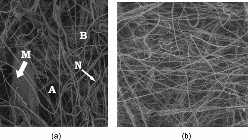
shows the micrograph of the sample nanofibers N with an average diameter of 270 nm, collected on the surface of microfibers M with an average diameter of 5 μ m. The nanofibers were obtained using the advanced melt-blown technique with on-line polymer processing in the extruder, developed in our laboratory. Regions of higher surface concentration of nanofibers (B) and regions with lack of such fibers (A) are observed when a single layer of nanofibers is collected, . This non-uniformity of the assumed thickness of a nanofibrous layer can be removed when multilayer nanofibrous structures are formed, . Our experiments in Podgórski et al. (2006), considering the filtration of nanoparticles of the 10–500 μ m range in a nanofibrous multilayer system, show that the filtration efficiency is strongly influenced by the structure of nanofibrous layers, especially for smaller aerosol particles. We would like to extend our considerations of nanoparticles filtration beyond the continuous regime, taking also into account the possibility of a non-uniform distribution of nanofibers at the front layer of the filter structure.
FIG. 1 Micrograph of the mono- (a) and multilayer (b) nanofibrous structures produced with modified melt-blown technique.
The aim of this paper is to determine the nonsteady-state deposition of nanoparticles on a locally observed system of two fibers, namely nano- and microsized, for different geometrical configurations of both fibers, as well as performance analysis of filter structures consisting of nano- and microfibrous layers of nanofibers with the non-uniform packing densities.
PROBLEM FORMULATION
The pattern of particle deposition in a fibrous filter is highly complex and intrinsically connected with the efficiency, loading capacity and permeability of the system. Therefore, rational design, optimization, operation, troubleshooting, and innovation require intimate understanding and reliable analysis of the deposition process and its effects on the system variables. During the initial period of filtration, aerosol particles are deposited on the collector surfaces forming chainlike agglomerates—dendrites. This phenomenon and its consequences were analyzed originally in the case of submicron particles deposited on the micron-size fibers, by CitationPayatakes and Gradoń (1980). Since then a significant progress in the production of fibrous materials, especially nanofibers, has been observed (CitationGradoń et al. 2005). Recently, the necessity to remove nanosized particles from a gas stream has required the construction of newly designed filters in which the composition of nanofibers and microfibers is used. In the present study we would like to discuss how the presence of nanofiber in the configuration with larger fiber affects the particle deposition pattern, and how the non-uniform distribution of nanofibers in the front layer of the bilayer filter structures affects filtration efficiency.
Bifiber System
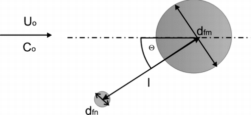
At the beginning, let us consider the system of two fibers of diameter d fm (micronsize) and d fn (nanosized) immersed in a stream of monodispersed aerosol particles (). The configuration is defined by the distance between the centers of both fibers (cylinders) and orientation angle Θ.
The aerosol flows normally to both cylinders (fibers) and the aerosol number concentration and velocity in an undisturbed region are C 0 and U 0, respectively. We assume that the surfaces of both fibers are absorption barriers for aerosol particles. The particle, when it touches the fiber, remains on its surface. The dominant particle transport mechanism is the convective Brownian diffusion. The efficiency of particle deposition on the surface of the fiber is a function of Peclet number, Pe = U · d ƒ/D, where D is the diffusion coefficient.
For the system considered here, two different length scales are observed if one compares the mean free path, λ, of the carrier gas molecule and the dimension of particular fiber d.
For an ideal gas modeled as rigid spheres, the mean free path of the molecules can be related to temperature T and pressure p, via
The continuum assumption of the Navier-Stokes equations, commonly used for the description of carrier gas velocity distribution, is valid, provided the mean free path of molecules is smaller than the characteristic dimensions of the flow domain. If this condition is violated, the fluid will no longer be under local thermodynamic equilibrium and the linear relationship between the shear stress and rate of shear strain (Newton's law of viscosity) cannot be applied. Velocity profiles, boundary wall shear stresses, mass flow rates and pressure differences will then be influenced by non-continuum effects. In addition, the conventional no-slip boundary condition imposed at a solid-fluid interface will begin to break down even before the linear stress-strain relationship becomes invalid. The ratio between the mean free path and the characteristic dimension of the flow geometry d is commonly referred to as the Knudsen number, Kn:
The value of the Knudsen number determines the degree of rarefaction of the gas and the validity of the continuum flow assumption (CitationPayatakes and Gradoń 1980). For Kn < 10−2, the continuum hypothesis is appropriate and the flow can be described by the Navier-Stokes equations using conventional no-slip boundary conditions. However, for 10−2 < Kn < 10−1 (commonly referred to as the slip-flow regime) rarefaction effects start to influence the flow and the Navier-Stokes equations can only be employed provided tangential slip-velocity boundary conditions are implemented along the walls of the flow domain. Beyond, Kn = 10−1 the continuum assumption of the Navier-Stokes equations begins to break down and alternative simulation technique approaches must be adopted. Finally, for Kn > 10, the continuum approach breaks down completely and the regime can then be described as being a free molecular flow. Under such conditions, the mean free path of the molecules is much greater than the characteristic length scale and, consequently, molecules reflected from a solid surface travel, on average, many lengths scales before colliding with other molecules.
The modeling of two-phase flow processes is an extremely difficult task within the classical hydrodynamics discipline owing, mainly, to the inherent free-boundary complication. The lattice-gas, and lattice-Boltzmann methods, which are based on the cellular automata concept, enjoyed rapid development and provided an interesting alternative to traditional numerical techniques for solving the Navier-Stokes equation (CitationPrzekop et al. 2003; Angelopulos et al. 1998). We have to emphasize that discrete models, because of their principles, do not operate directly with the physical quantities characteristic for continua. The dimensional numbers involving these quantities are commonly used.
Digital Fluid Dynamics (DFD)
The description of particle motion in a fluid requires the knowledge of the velocity field of the fluid and particle position at any site of space and moment of time. For the purpose of this work, fluid dynamics is described by the lattice-Boltzmann model, while the solid particle motion is modeled by the Cellular Automata probabilistic model.
The readers can find general information about the fundamentals of the lattices in the references cited below. We will introduce here only some basic information which is necessary for further analysis. The concept of lattice applied to fluid dynamics is based on Ulam's works on cellular automata (CitationUlam 1952). Fluid dynamics, especially, is a sufficiently large system for cellular automaton formulation because there are two rich and complementary ways to picture fluid motion. The kinetic picture, in which many simple atomic elements rapidly collide with simple interactions, tallies with the infinitive picture of dynamics in a cellular space.
The classical approach to the flow phenomena is through partial differential equations (Navier–Stokes equations) that describe collective motion in a dissipative fluid. The kinetic theory models a fluid by using an atomic picture and imposing Newtonian mechanics on the motion of atoms.
Complete information on the statistical description of a gas at, or close to, the thermal equilibrium is assumed to be contained in the one-particle phase-space distribution function ƒ (x, t, Γ) for the atomic constituents of the system. The variables x and t are the space and time coordinates of the atoms and Γ stands for all other phase-space coordinates, e.g., momentum flux or momentum.
For an isolated gas with collisions the Liouville theorem is modified to the form:
The lattice gas methods were those of a pure cellular automaton (CitationHardy et al. 1976; CitationFrisch et al. 1986). Models using this approach assume a totally discrete physical space, time and the node-state. The considered population consists of a set of identical particles (each with unit mass, moving with the same average velocity). The particles occupying the same node collide at each time step. The exclusion principle says that there cannot be more than one particle in the node, moving in the same direction. The collision rules conserve mass and momentum. After collision, a particle moves into the nearest neighbor site on its moving direction. The lattice gas algorithms are very stable and can handle complicated geometry and boundary conditions. The weakness of these methods is that they are “noisy,” requiring spatial and time averaging.
The lattice-Boltzmann model was the next step in developing such a description of fluid dynamics problems, CitationMcNamara and Zanetti (1988). In the case of the lattice-Boltzmann approach, the node state is described by a continuous function.
The analysis of deposition of aerosol particles and description of the structure of growing agglomerates require the knowledge of fluid motion and particle displacement in the considered region.
The Fluid Model
The nine-speed square lattice was used for modeling the fluid flow. The function ƒ i (x,t) denotes the number of fluid particles entering site x at time t with velocity e i , which is the unit vector in the i-th direction. Macroscopic quantities such as density ρ or momentum ρ u are defined as:
The outcome of a collision can be approximated by assuming that the momentum of interacting particles will be redistributed at some constant rate toward equilibrium distribution ƒ i eq (CitationQian et al. 1992). This simplification is called the single-time-relaxation approximation and can be expressed by the equation:
The rate of change toward equilibrium is 1/τ, the inverse of relaxation time, and is chosen to produce the desired value of fluid viscosity:
The equation of state for a discrete space takes the form:
SLIP-FLOW BOUNDARY CONDITIONS
In traditional (continuum) flow analyses, a no-slip velocity constraint is enforced along all solid-fluid interfaces. The notion behind the no-slip condition arises from the fact that there should be no discontinuities in the velocity field within the fluid as this would give rise to infinite velocity gradients and therefore infinite shear stresses. A similar argument can be employed for conditions at the wall. However, the no-slip constraint is strictly valid only if the fluid adjacent to the surface is in local thermodynamic equilibrium; a condition which requires a very high frequency of molecular collisions with the wall. In practice, the no-slip condition is found to be appropriate provided the Knudsen number, Kn < 10−2. If the Knudsen number is increased beyond this value, rarefaction effects start to influence the flow and the molecular collision frequency per unit area becomes too small to ensure thermodynamic equilibrium. Under such conditions, a discontinuity in the tangential velocity will form at any solid-fluid interface.
SLIP-REFLECTION MODEL
In continuum regime, the bounce-back boundary condition is used on the solid level. This means that when a fluid particle enters the solid site, it changes its moving direction for the opposite one. This method naturally leads to zero-velocity at the solid level.
Our model involves two parameters: r, s, representing the probability for a fluid particle to be bounced back and slipped forward, respectively. The boundary kernel takes the form, CitationSucci (2002):
Obviously, the two parameters are not independent and must be chosen such that r + s = 1. Assuming second order slip velocity, one can write
The Knudsen number for lattice is given by ν/(c s d). Parameters A and B are given by:
The analytical solution for the fully continuum case gives the values of A = 1.146 and B = 0.907 (CitationCercignani 1975). The value of A can be obtained by assuming r = 0.603. B is equal to 3.
The Solid Particles Motion Model
CitationChopard and Masselot (1999) proposed a model which was used in this work for the description of solid particles motion. In the model, N i (x, t) denotes the number of aerosol particles entering the site x at time t with velocity e i . Solid particles move to the neighboring nodes at each step in time. The particles at the site x move to the site x+u·Δt during a period of time from the range (t, t+Δt), with the velocity of gas (u). Usually, x+u·Δt does not correspond to a lattice node, so to compute the number of particles reaching each neighboring node, we use a randomized algorithm. The probability of an aerosol particle displacement, p i ,
RESULTS AND DISCUSSION
The models described in the previous chapters were used to simulate the deposition of diffusional particles in the system of two cylindrical collectors (). A cylinder of diameter d fm was placed centrally in the computational domain. A three-dimensional cubic model with 19 moving directions of gas “molecules” and aerosol particles was used in our simulations. The lattice had a dimension of 256 × 256 × 32 nodes. The diameter of the filter microfiber was equal to 64 nodes and the nanofiber and particle diameters were represented by 1 node. The distance between the centers of the fibers was assumed to be l = 64 nodes. In the fluid inlet, plug flow distribution was assumed and no-gradient velocity condition was applied in the outlet or stress on the boundaries normal to the main gas flow. The calculations were carried out assuming r = 0.6 for nanofibers and no-slip boundary conditions on microfibers.
The calculations were carried out for the Reynolds number related to the microfiber Re m = 10−4, which corresponds to the Reynolds number for a fiber of 100 nm diameter and air velocity 1.5 cm/s, which is a common value of gas velocity in fibrous filters. The values of fluid velocity and viscosity were chosen to obtain the desired values of the Reynolds and Knudsen numbers. The diffusion coefficient, and k 0 in the next step, was determined from the assumed value of the Péclet number. The values of k 0 were of the range 0.01–0.2. The dimensionless numbers were calculated as follows
The calculations of particle deposition efficiency were carried out using the collection efficiency definition from classical filtration theory for the microfiber (the fraction of particles flowing towards the collector that make contact with the collector or particles that have already been deposited).
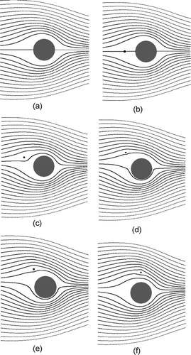
The velocity contours for Re m = 10−4 and nanofiber Knudsen number Kn = 1.0, for different orientation angle Θ, are shown in the . It can be observed that the nanofiber does not perturb the velocity distribution near the microfiber very significantly, especially for the Θ < 45°. Estimated velocity gradients around the nanofiber are higher than those at the microfiber. It causes increased diffusional deposition of the nanoparticles. Strong convectional gradients “prepare” the system for intensive dissipative effects responsible for increasing the entropy of the system. Diffusion predominates deposition effects. Complementary to the velocity contours, represents the gas streamlines around fibers for the same positions of fibers as it is in .
FIG. 3 Velocity contours, Knudsen number related to nanofiber Kn n = 1.0; (a) single microfiber, and micro- and nanofiber system for following positions of the nanofiber: (b) Θ = 0°, (c) Θ = 30°, (d) Θ = 45°, (e) Θ = 60°, (f) Θ = 90°.
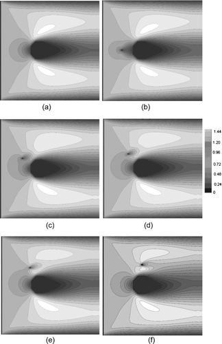
FIG. 4 Streamlines, Knudsen number related to nanofiber Kn n = 1.0; (a) single microfiber, and micro- and nanofiber system for following positions of the nanofiber: (b) Θ = 0°, (c) Θ = 30°, (d) Θ = 45°, (e) Θ = 60°, (f) Θ = 90°.
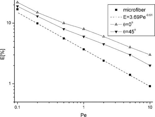
The efficiency of particle deposition on both fibers was calculated in the next step of our investigations. shows the collection efficiency of nanoparticles on single microfiber and microfiber-nanofiber systems as a function of the Peclet number, related to the microfiber, for two values of Θ of the nanofiber position. In classical filtration theory, CitationStechkina and Fuchs (1966), the single fiber efficiency E ∼ Pe −2/3. In our calculations, using the lattice-Boltzmann method, we have achieved the best fitted curve for E ∼ Pe −0.61. The nanofiber placed in front of the microfiber (Θ = 0°) is exposed to the aerosol flow forming higher velocity gradients than the fiber placed in position for Θ = 45°. It causes more efficient particle deposition on this fiber. This results show the consistency of continuous and discrete modeling applied for the same physical situation.
FIG. 5 Deposition efficiency of nanoparticles on microfiber and nanofiber for two positions of the nanofiber Θ = 0° and Θ = 45° as a function of Peclet number and fixed Kn n = 1.0.
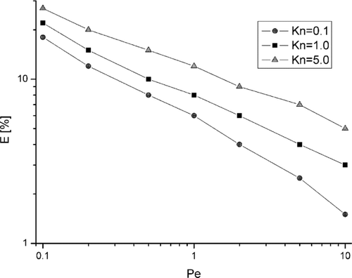
The relation between filtration efficiency of the microfiber and the nanofiber system as a function of the microfiber Peclet number, for different values of the Knudsen number, is shown in . One can observe a significant effect of the Knudsen number on deposition efficiency, especially for small Peclet numbers, when diffusion predominates. The convective effect (higher values of Pe) moderates this behavior.
FIG. 6 Deposition efficiency of nanoparticles as a function of Peclet number for different values of Knudsen number related to nanofiber Kn n , and for position of nanofiber Θ = 0°.
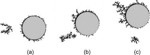
We have extended these calculations for longer exposure times of the filtration. presents the 3D qualitative patterns of deposited particles on the system of nano- and microsized fibers (Θ = 0) during non-steady state filtration. It can be observed that the efficient deposition of particles on the nanofiber causes a drop in the deposition on the microfiber, especially when the part of the microfiber is shadowed by the nanofiber. The nanofiber in this system becomes strong attractor for diffusional deposition. The influence of the nanofiber orientation, with respect to the microfiber position, during the loading of fibers with deposited particles is shown in . Calculations, only for this case, were reduced to 2D just for the purpose of clear presentation of the results on the plane. When the position of the nanofiber changes from the front () to the Θ = 90° (), the microfiber is exposed to aerosol particles and more of them are deposited on the microfiber. Simultaneously, velocity gradients around the nanofiber decrease and less particles are deposited on the nanofiber (). Such calculations will be used at the next step of our modeling, 3D, for the nonsteady-state filtration in a multifiber system.
FIG. 7 Patterns 3D of deposited particles structures on the nano- and microfiber system; Re m = 10− 4, Kn = 1.0, Pe = 2.0, (a) Θ = 0°, (b) Θ = 45°
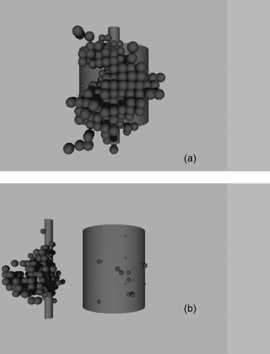
FIG. 8 Patterns 2D of deposited particle structures on the nano-microfiber system for three positions of nanofiber: (a) Θ = 0°, (b) Θ = 45°, and (c) Θ = 90°; Re m = 10−4, Kn = 1.0, Pe = 2.0.
Bilayer Filter Model
The next step of our modeling was devoted to calculating the performance of the filter consisting of two fibrous layers. The front layer of the filter is made of nanofibers and the rear (supporting) layer of the filter is made of microfibers. The structure of the monolayers of nanofibers produced by electrospinning or modified melt-blown techniques (CitationGradoń et al. 2005), are locally strongly non-uniform. One can observe regions with locally concentrated fibers and large empty spaces with no fibers when observation is reduced to a small-scale object, comparable with fiber diameters.
Taking the above into account, we analyze the behavior of the bilayer filter for three cases—uniformly distributed nanofibers on the microfiber backing layer, and two patterns with nonuniform distribution (locally concentrated) nanofibers. The backing layer of the filter consists, for all cases, of microfibers distributed uniformly in the space. Due to limited computational abilities of the available equipment, the model of the filter structure was reduced to a small scale.
The calculations of particles deposition were performed for the lattice of 512 × 768 × 64 dimension. The nanofiber filter structure had dimension 512 × 256 × 64 nodes and its mean porosity was ϵ = 95%. The fiber diameter was equal to 1 node of the lattice. The microfiber structure had dimension of 512 × 512 × 64 nodes and its porosity was also ϵ = 95%. The microfiber diameter was equal to 64 nodes of the lattice. The fibers have hexagonally ordered structures in both layers. The calculations were carried out for three different structures of a nanofibrous layer (). In the first case (A) nanofibers were distributed uniformly in the whole layer volume (ϵ = 95%). In the second (B) and third (C) case, the structures of the dimensions 64 × 128 × 64 and 64 × 64 × 64 nodes and porosity, in the regions of concentrated fibers (shadowed regions), was equal to 90% for structure B and 80% for structure C, respectively. The regions that included fibers were adjacent to the regions without nanofibers, ϵ = 100%, (empty space for structures B and C). The number of nanofibers in the front layer of the filter was the same for all tree cases. The average porosity of non-uniform nanofiber distribution for models B and C was the same as in case A and was equal to 95%.
FIG. 9 Bilayer filter structures with uniform A, and nonuniform (B, C) distribution of nanofibers in the front layer.

Calculations of an initial pressure drop and filtration efficiency were made for different sets of operating conditions, given by the Reynolds, Peclet, and Knudsen numbers.
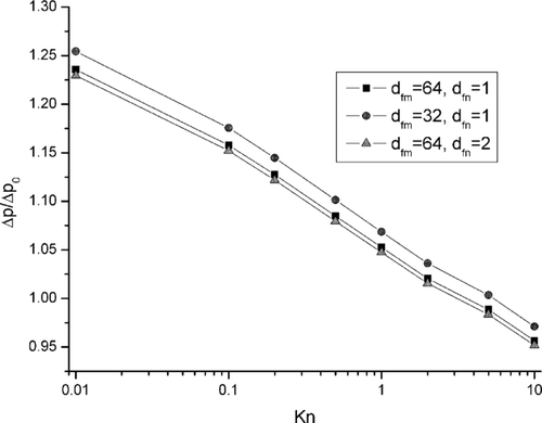
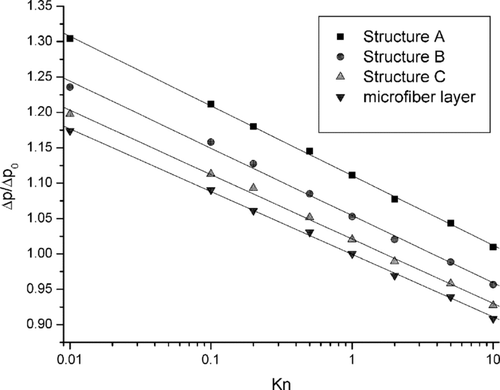
The pressure drop, Δ p, of the aerosol flow through the filters structures A, B, and C, related to the pressure drop Δ p 0 calculated for aerosol flow through the microfibrous backing layer at the Kn = 1, as a function of the Knudsen number is shown in . The pressure drop was calculated for the Reynolds number, related to the nanofiber diameter, equal to 1· 10−4.
FIG. 10 Initial pressure drop to filter structures A, B, and C as a function of Knudsen number. Δ p0 denotes pressure drop for microfiber layer and Kn = 1.0.
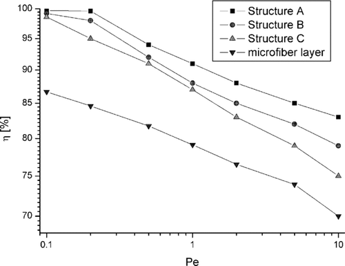
presents the relation between initial filtration efficiency and the Peclet number for three bilayer filter structures and the back filter layer only. The Knudsen number equaled Kn = 1 and the Reynolds number related to nanofiber—Re = 1· 10−4. Difference in the pressure drop are relatively significant for different filter structures due to possible channeling of the gas flow, especially structure C, and are similar for all values of Kn. However, the differences in filtration efficiency, for diffusional particles are not very significant.
For small Pe values (close to zero), when deposition is due to pure diffusion, there is no difference in filtration efficiency for all filter structures. All three structures have the same surface area of nanofibers. Deposition efficiency on nanofibers is very high, and the length scale of the particle displacement for high values of Kn causes aerosol particles not to “recognize” differences in the filter structure. This effect is reduced when Pe increases, and convection plays an important role in particle deposition. Filtration efficiency decreases and differences of this parameter are more significant for different filter structures because of the channeling effect (convective diffusion).
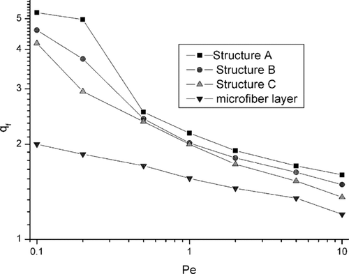
Relation between the quality factor, defined as qƒ = − lnP i /(Δ p/Δ p 0), (where P i is penetration of particles through the filter, P i = (1−η), and Δp pressure drop), and the Peclet number is shown in . As one can see, the quality factor of micro- and nanofibers composites does not differ significantly, although higher values are observed for uniform distribution of nanofibers in the filter structures. It indicates that the effect of a pressure drop predominates in the evolution of the filter performance as pointed out by the quality factor definition. The quality factor of the microfiber layer is much lower, especially when the diffusional effect predominates (small values of the Peclet number).
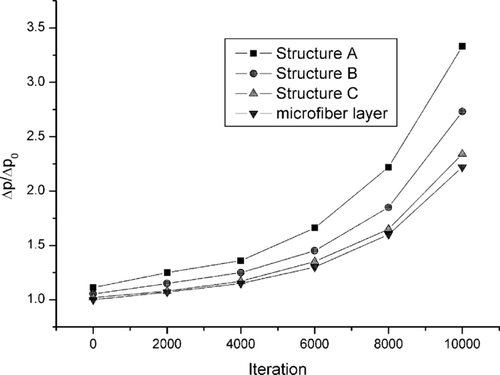
The next step of our research was devoted to the analysis of non-steady state performance of filter structures. In this work we present the results of calculations obtained for the Knudsen and Reynolds numbers related to the nanofiber equal, respectively Kn = 1.0 and Re = 1· 10−4, and for the particle the Peclet number Pe = 2.0. The volume fraction of particulate matter in the inlet gas stream was equal to 0.01.
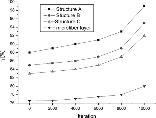
shows pressure drop evolution during the filter loading. The exposure time is emphasized through the number of iterations is the procedure of calculations. The Δp 0 denotes the initial pressure drop for the air flow through the microfibrous layer of the filter. The pressure drop for structure C is much smaller than for structures A and B, and is comparable to the pressure drop of microfiber layer. It is also related to the stronger effect of channeling in this structure in comparison to structures A and B (see also ).
presents the filtration efficiency throughout filter loading. These results are consistent with these shown in and . When particles are deposited on fibers, the porosity of structures decreases, which leads to an increase in both, pressure drop and filtration efficiency.
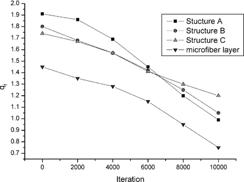
The evolution of the quality factor of filter structures with exposure time is shown in . The quality factor of structure C decreases much more slowly than for structures A and B. The possible explanation of this phenomenon is that dendrite structures formed by deposited particles grow also towards the regions of 100% porosity, which are more densely packed in structure C. The influence of this effect on filtration efficiency is higher than on pressure drop. The filter with structure C clogs more slowly than filters A and B.
FIG. 15 Time evolution of the quality factor for different filter structures A, B, and C during filter loading.
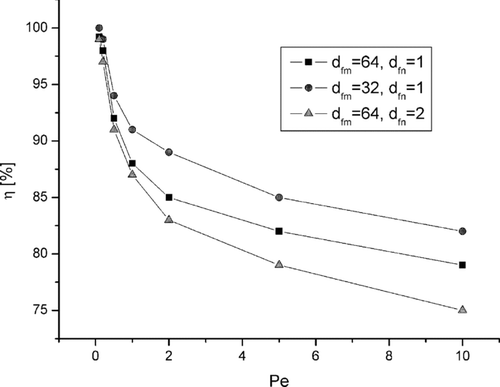
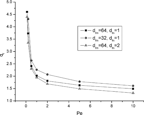
, , show the effect of micro- and nanofibers diameters combination on pressure drop, filtration efficiency and quality factor. In the first additional case, the microfiber size was decreased to 32, and in the second one, the nanofiber diameter was increased to 2. Calculations were carried out for structure B () for the same gas flow and diffusion coefficient of particles. The dimensionless numbers describing the figures are related to the diameters combination discussed in the previous paragraphs. As one can see, a decreasing microfiber diameter increases slightly the pressure drop, but also results in higher filtration efficiency. An increased nanofiber diameter has no influence on the pressure drop, but results in decreased collection efficiency. The highest quality factor is obtained for the combination of small microfibers and small nanofibers. Reduction of the diameter of fibers causes the increasing of the total surface area of fibers in the filter structure of the same volume and porosity.
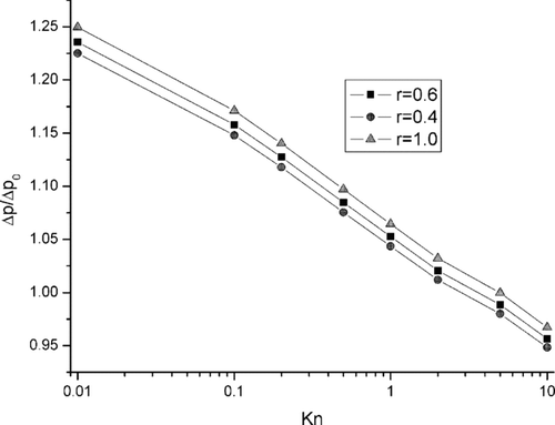
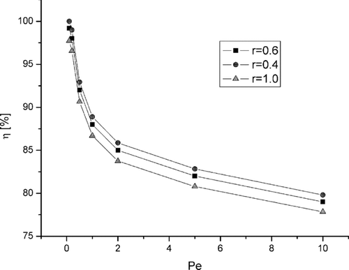
and show the influence of the fluid particle reflection parameter r on the pressure drop and filtration efficiency, respectively, for different values of Knudsen and Peclet numbers. The conditions of calculation were the same as those for and done for filter structure B (). As one can see, the assumption of higher values of r results in the prediction of a higher pressure drop and smaller collection efficiency. The higher values of r determine the reduction of the effect of fluid particle slipping towards the main direction of the gas flow. It results in decreasing of the energy dissipation according to the model described above.
CONCLUSIONS
The lattice-Boltzmann model is a useful tool to describe the growth dynamics of structures of deposited matter during the flow of aerosol particles through a system of micro- and nanosized fibers. This method can be effective in cases when the continuum approach breaks down and boundary conditions for the solution of the Navier-Stokes equation describing the local and temporary velocity distributions change significantly due to the development of a complicated structure of deposits. This effect cannot be modeled using the classical continuum approach. As a consequence, changes in the deposition efficiency of the aerosol particles during filter loading can be observed.
The proposed model is useful for the calculation of deposition efficiency on a single fiber as well as filtration efficiency of the assumed filter structures for high Knudsen numbers. Proposed model makes possible the observation of the evolution of the filter quality during its loading with filtered out particles. It is particularly important for designing nanostructured fibrous filters envisaged for the removal of nanoparticles from the ambient or technological gases.
ACKNOWLEDGMENTS
This work was supported by the Cummins Filtration Ltd, USA.
REFERENCES
- Angelopoulos , A. , Paunov , V. N. , Burganos , V. N. and Payatakes , A. C. 1998 . Lattice-Boltzmann Simulation of Nonideal Vapor-Liquid Flow in Porous Media . Phys. Rev. E. , 57 : 3237 – 3245 .
- Boltzmann , L. 1995 . Lectures on Gas Theory , New York : Dover Publishing .
- Cercignani , C. 1975 . Theory and Application of the Boltzmann Equation , New York : Scottish Academic .
- Chopard , B. and Masselot , A. 1999 . A Cellular Automata and Lattice Boltzmann Methods: A New Approach to Computational Fluid Dynamics and Particle Transport . Future Generation Computer Systems , 16 : 249 – 257 .
- Dorfmann , J. R. 1999 . An Introduction to Chaos in Nonequilibrium Statistical Mechanics , Cambridge : Cambridge University Press .
- Filippova , O. and Hanel , D. 1997 . Lattice-Boltzmann Simulation of Gas-Particle Flow in Filters . Computers and Fluids , 26 : 697 – 712 .
- Frisch , U. , Hasslacher , B. and Pomeau , Y. 1986 . Lattice-Gas Automata for the Navier-Stokes Equation . Phy. Rev. Lett. , 56 : 1505 – 1508 .
- Gradoń , L. , Podgórski , A. and Balazy , A. Filtration of Nanoparticles in the Nanofibrous Filters . FILTECH EUROPA 2005—Conference Proceedings . Wiesbaden, Germany. vol. II , pp. 178 – 185 .
- Hardy , J. , de Pazzis , O. and Pomeau , Y. 1976 . Molecular Dynamics of Classical Lattice Gas: Transport Properties and Time Correlation Functions . Phys. Rev. A , 13 : 1949 – 1961 .
- Hirschfelder , J. O. , Curtiss , C. F. and Bird , R. B. 1954 . Molecular Theory of Gases and Liquids , New York and London : Jon Wiley and Son, Chapman and Hall .
- Masselot , A. 2000 . A New Numerical Approach to Snow Transport and Deposition by Wind: A Parallel Lattice Gas Model , Ph.D. Thesis Geneve University .
- Maurer , J. , Tabeling , P. , Joseph , P. and Willaime , H. 2003 . Second Order Slip Laws for Helium and Nitrogen . Physics of Fluids , 15 : 2613 – 2621 .
- McNamara , G. G. and Zanetti , G. 1988 . Use of the Boltzmann Equation to Simulate Lattice Gas Automata . Phys. Rev. Lett. , 61 : 2332 – 2335 .
- Payatakes , A. C. and Gradoń , L. 1980 . Dendritic Deposition of Aerosols by Convective Brownian Diffusion for Small, Intermediate and High Particle Knudsen Numbers . AJChE J. , 26 : 443 – 454 .
- Podgórski , A. , Baazy , A. and Gradoń , L. 2006 . Application of Nanofibers to Improve the Filtration Efficiency of the Most Penetrating Aerosol Particles in Fibrous Filters . Chem. Eng. Sci , 61 : 6804 – 6815 .
- Przekop , R. , Moskal , A. and Gradoń , L. 2003 . Lattice-Boltzmann Approach for Description of the Structure of Deposited Particulate Matter in Fibrous Filters . J. Aerosol Sci. , 34 : 133 – 147 .
- Qian , Y. H. , d'Humieres , D. and Lallemand , P. 1992 . Lattice-BGK Models for Navier-Stokes Equation . Europhysics Letters , 17 : 479 – 484 .
- Stechkina , I. and Fuchs , N. 1966 . Studies on Fibrous Aerosol Filters—I. Calculations of Diffusional Deposition of Aerosols in Fibrous Filters . Ann. Occupat. Hyg , 9 : 59 – 64 .
- Succi , S. 2002 . Mesoscopic Modeling of Slip Motion at Solid-Fluid Interfaces with Heterogeneous Catalysis . Phys. Rev. Lett. , 89 : 64502
- Ulam , S. Random processes and transformations . Proceedings of the International Congress of Mathematicians . August 30–September 6 1950 , Cambridge, Massachusetts. vol. 2 , pp. 264 – 275 . Providence, RI : American Mathematical Society .
