Abstract
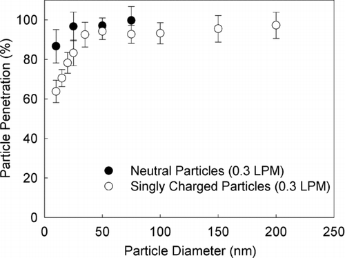
We have developed a low-cost, miniaturized disk-type electrostatic aerosol precipitator for a personal nanoparticle sizer, often needed in applications requiring spatially distributed measurement or personal exposure monitoring. The performance of prototype mini-disk precipitator was evaluated in this study. Measurement of particle transmission through the precipitator for both neutral and singly charged particles shows that the compact size of the disk precipitator does not lead to serious particle loss resulting from particle diffusion and/or electrical image force. The transmission of singly charged particles of 10 nm is 64% at an aerosol flowrate of 0.3 lpm. The device consists of two precipitation chambers, separated by a metal disk. The design further allows the device to be configured to precipitate charged particles by establishing electrical fields in one or both precipitation chambers. Both operations work well to precipitate particles by electrical mobility. The operation of dual-chamber precipitation, with electrical field established on both sides of the middle disk, is preferred since it lowers the maximum requirement of applied voltage to precipitate particles with a specific electrical mobility for a given flowrate. Semi-empirical models were also developed to describe the dependence of the particle penetration curves on particle electrical mobility.
1. INTRODUCTION
Particles in the submicron and nanometer range have been reported in the exhausts of different combustion sources, chemical processes and aerosol reactors (CitationKauppinen 1990; CitationBiswas and Wu 2005). Examples include the exhausts of diesel and jet engines, the emission from coal-combustion power plants, and welding fumes. Such nanoparticulate matter is considered environmental pollution, and thus harmful (CitationWarheit 2004). Separately, many modern industrial applications have begun to utilize nanoparticles as part of a growing technology. For example, the photocatalysis of nano-sized TiO2 has been proposed or implemented for many practical applications including bacteria sterilization, oxidation of soot particles, decomposition of kitchen oils, super-hydrophilic surface coating, and hydrogen production (CitationFujishima et al. 1997). Nanoparticles of different materials are synthesized in chemical reactors for a variety of modern industrial applications (CitationMaynard and Kuempel 2005; CitationBiswas and Wu 2005), and are the building blocks for the recent national initiative in nanotechnology in the United States. Meanwhile, the number of scientific publications on the toxicity of newly synthesized nanoparticles is increasing (CitationWarheit 2004; CitationOberdörster et al. 2005). Workers in current and future nanotechnology-related manufacturing facilities are increasingly likely to be exposed to nanoparticles. It is thus desired to develop a low-cost, miniaturized personal device for monitoring workers' exposure to nanoparticles.
Currently available instruments to measure particle size distributions in submicron and nanometer range, e.g., scanning mobility particle sizer (CitationWang and Flagan 1990), are primarily designed for scientific studies. These instruments provide good size resolution and sensitive particle concentration detection. However, they are also overly large and expensive for use as personal particle monitors. Existing personal particle samplers are primarily focused on particles with sizes larger than 0.1 μ m. In these devices, particles are initially separated by inertial effects, and the particle mass collected on different stages of impactors or cyclones are measured manually after exposure (CitationLee et al. 2006; CitationMisra et al. 2002; CitationKoch et al. 1999; CitationChen et al. 1999). These instruments have been widely applied for particulate measurements in indoor, outdoor, and personal environments (CitationLiu et al. 2002, CitationMader et al. 2001). While the inertial-separation based technology works well in classifying particles in the supermicron and larger submicron range, they are impractical for particles of much smaller diameters. Electrical-mobility based techniques are better suited for measuring particles in the submicron and nanometer ranges. A typical electrical-mobility-based particle sizer consists of three essential components: a particle charger to electrically charge sampled particles to a known charge distribution, a particle-electrical-mobility-based separator to size particles and an aerosol counter to measure the concentration of sized particles. To develop the miniaturized version of electrical mobility particle sizer we will need to have a miniaturized aerosol charger, a particle separator and a particle counter. The radioactive neutralizer commonly used in SMPS could be used as the aerosol charger because of its simplicity and reproducible charge distribution. However, the safety regulation of radioactive sources limits its application for distributed measurement or personal monitoring. Corona-discharge-based unipolar charger is another option for particle charging but the problems of multiple charges and being affected by environmental factors complicate the data reduction for the sizer. For particle counting, miniaturized aerosol electrometer and condensation particle counter (CPC) are two potential options. Due to the sensitivity of small current measurement, aerosol electrometers are in general more suitable for counting particles with the concentration larger than 150 particles/cm3 at the aerosol flowrate of 0.3 lpm. CPC has the potential to count particles at the concentration lower than that detectable by aerosol electrometers. The portability and robustness of miniaturized CPCs are however questionable because of the use of working fluid in the devices. Therefore, the selection of aerosol charger and counter for a miniaturized particle sizer will depend on specific applications and remains unanswered.
In this study, we have designed and constructed a prototype miniaturized electrostatic aerosol precipitator, more suitable to be used in a miniaturized electrical mobility particle sizer. Low cost solution with great miniaturization takes the highest priority in the design. Among different types of electrical mobility analyzer designs, the simplest one is the precipitation type. Both the cylindrical and disk configurations of precipitators have been constructed and studied in the literature. The performance of a precipitator is characterized by the penetration efficiency as a function of applied voltage at a fixed aerosol flowrate. A critical electrical mobility Zpc for any given voltage can then be determined from the penetration curves. Charged particles having electrical mobility larger than Zpc are completely precipitated by a given voltage. Particle size distribution can be obtained by stepping the voltage through the entire range and measuring the electrical charges associated with penetrating particles (CitationAdachi et al. 1991; CitationForsyth et al. 1998). A disk-type electrostatic aerosol precipitator was first studied by CitationHurd and Mullins (1962). The basic construction consists of a central metal disk sandwiched between two parallel metal disk electrodes. Electrically insulating spacers create two flow chambers between the middle and top/bottom disks. An electrically charged aerosol flow is introduced into the top flow chamber by a straight tube connected to the centre of the top disk, and flows radially outwards. By creating an electrical field across the flow chamber, particles with sufficient electrical mobilities are removed from the aerosol stream. The outflow is then directed to the flow chamber between the middle and bottom disks through an annular slot. In this bottom flow chamber the aerosol flow moves inward and converges to an exit tube connected to the centre of the bottom disk. No electrical field is established in the bottom flow chamber since it is used for aerosol transport only. The diameter of the device developed by Hurd and Mullins is about 203.2 mm (8 inches) in diameter, and the thickness of the flow chambers is 2 mm.
Our new mini-disk precipitator modifies the Hurd and Mullins design to utilize both top and bottom flow chambers for particle removal. This operational change further makes this new device more compact. We have also developed a simple model to predict the performance of particle removal for this new disk-type electrical aerosol precipitator under the proposed operational condition.
2. AEROSOL PRECIPITATOR AND EXPERIMENTAL SETUP
2.1. Construction of Mini-Disk Electrostatic Aerosol Precipitator
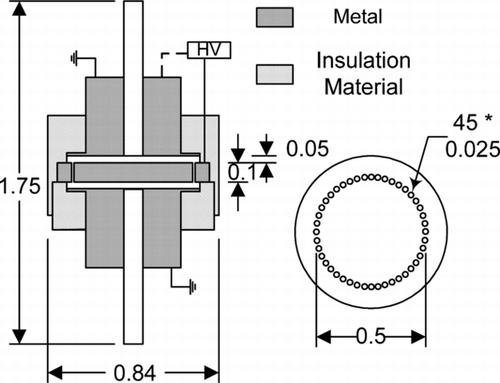
The mini-disk electrostatic aerosol precipitator is weighted only 24 grams, and its design and dimensions are shown in . The basic construction sandwiches the middle metal disk between symmetric top and bottom metal plates, using electrically insulating spacers to create two equal flow chambers 0.05 inch high (1.27 mm). An annulus of small orifices is located close to the outer edge of the middle disk, connecting the top and bottom flow chambers. An electrically charged aerosol stream is introduced into the top flow chamber through the central tube connected to the top plate. The other central tube connected to the bottom plate is used as the aerosol flow exit. Voltage can be applied through a high voltage cable connected to the outer edge of the middle disk. The top and bottom metal plates can be either electrically grounded or biased to separate potentials with respect to the middle disk. This option allows users to configure the device to establish independent electrical field in either flow chambers. The aerosol enters the device from one of the central tubes, moves outwards radially, passes through the orifices, and converges radially to the opposite central exit tube.
When a fixed electrical field is established on either chamber, the trajectories of charged particles are deflected. All particles with sufficiently large electrical mobilities will be deposited on the plates, and those with lower mobilities will partially or fully escape and exit the device. When integrated into the nanoparticle sizer, a sensitive aerosol electrometer can be used downstream of the device to measure the concentration of escaped charged particles. In this study, we focused on the laboratory evaluation of the precipitator's performance as an electrostatic aerosol classifier, so an Ultrafine Condensation Particle Counter (UCPC, TSI 3025A) was used to count particle number concentration.
2.2. Experimental Setup for the Performance Evaluation of Prototype Precipitator
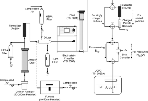
Shown in is the schematic diagram of the experimental setup for the evaluation of the disk electrostatic aerosol precipitator. The disk precipitator was tested with laboratory generated test particles in the size range of 10–200 nm, both neutral and charged. Monodisperse test particles (NaCl) in the size range of 50–200 nm were produced using the atomizer-Differential Mobility Analyzer (DMA)-classification technique (CitationLiu and Pui 1974). For particles of diameters less than 50 nm, monodisperse silver particles were generated by the evaporation-condensation-DMA-classification technique with a tube furnace (CitationScheibel and Porstendörfer 1983). For all particle sizes, the transmission efficiencies through the disk precipitator with the disk and all plates electrically grounded were measured for both singly charged and neutral particles. Electrically neutral particles were obtained by passing charged particles classified by a DMA, through a Po210 neutralizer and a home-made charged particle remover, consisting of a high voltage electrode and a grounded outer housing. Particle number concentrations upstream and downstream of the disk precipitator, Nup and Ndn(0), were measured by a UCPC operated at the low flow mode (0.3 lpm), and the particle transmission efficiency was then obtained as the ratio of Nup and Ndn(0) shown in Equation (Equation1):
In the measurements of both particle transmission and cutoff curves, the flowrate through the disk precipitator was set at 0.3 lpm and controlled by the UCPC operated at the low flow mode. The low flowrate operation is preferred because it reduces the voltage required to precipitate all the particles with a given electrical mobility, and consequently reduces the size of the required air mover. This further translates into energy saving and improvement of device portability for the targeted applications. The selection of 0.3 lpm was based on the fact that for measuring singly charged particles up to 300 nm in diameter, it would require the voltage about 7.6 kV applied on the prototype when using only one precipitation chamber. The operation of test prototype with the flowrate higher than 0.3 lpm will require to apply even higher voltage to precipitate singly charged particles of 300 nm in diameter. It is therefore undesired to operate the prototype with the flowrate high than 0.3 lpm. The aerosol flowrate selection is also due to the availability of miniaturized pump to be used with the prototype.
3. RESULTS AND DISCUSSION
3.1. Particle Penetration
Two reasons led us to perform the particle penetration measurements. One concern in developing a compact aerosol classifier is particle loss. As shown in , the size of the flow chambers between the end plates and middle disk are much reduced. Even without the voltage applied, charged particles could be deposited by electrical image forces if they travel close to the grounded metal plates. The second reason for performing particle penetration measurements is that the data will be needed in the data reduction process to recover the particle size distributions being sampled.
The experimental particle transmission through the prototype disk aerosol precipitator for singly charged and neutral particles is shown in . Monodisperse particles between 10 and 200 nm were used for these measurements. More than 85% penetration is measured for neutral particles larger than 10 nm. The loss of neutral particles is solely due to diffusion. A greater proportion of charged particles are lost than neutral particles. This tendency is especially marked for particles smaller than 50 nm. The loss of singly charged particles increases as particle size reduces. It indicates, in addition to the particle diffusion, that image forces do play the role in the loss of charged particles. At 10 nm in diameter the particle penetration through the prototype reduces to 64%, which is still considered enough for subsequent precipitation measurement and analysis.
3.2. Precipitation Measurement
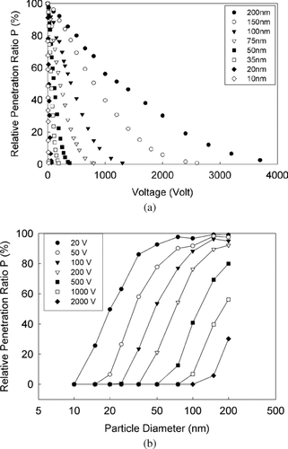
Given the geometry of the precipitator, at a fixed operational flowrate the performance is characterized by the particle cutoff curve (or transfer function), i.e., the particle penetration as a function of voltage applied to the middle disk. Although the prototype aerosol precipitator is designed to make use of both flow chambers, it is useful to evaluate its performance when electrical field is established in only one flow chamber, as in the study of CitationHurd and Mullins (1962). This condition was used to investigate the basic device performance, and to evaluate the presence of possible manufacturing defects. For this evaluation, the top plate with the inlet tube was electrically grounded, and both the middle disk and the bottom plate with the outlet tube were set at the same voltage. Shown in are the particle cutoff curves for different particle sizes. In the figure, the penetration is normalized to 100% with no voltage applied. As expected, larger particles require higher voltage than smaller particles to achieve the same penetration. The results demonstrate that the disk precipitator is capable of differentiating particles of different sizes by virtue of their electrical mobilities. Further, penetration is a linear function of the applied voltage for a given particle size. This result is consistent with the performance of much larger electrostatic precipitators (CitationForsyth et al. 1998). The particle precipitation results (relative penetration ratio P) were also plotted against particle diameter for different applied voltage, as shown in . Such information will be useful to determine critical electrical mobility Zpc for any given voltage.
FIG. 4 Particle cutoff curves of the mini-disk aerosol precipitator for single chamber precipitation (Q = 0.3 lpm).
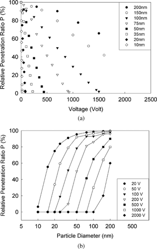
As stated in the introduction, the miniaturization of the precipitator is one of our primary goals. Making use of the flow chambers located at the top and bottom of the middle disk in the prototype device is thus proposed for particle precipitation. This is obtained by applying a high voltage on the middle disk and keeping both top and bottom plates electrically grounded. The proposed operation also reduces the maximum voltage required to completely deposit particles of a given electrical mobility. The experimental particle cutoff voltage curves using both flow chambers are shown in and , and exhibit similar trends to those seen in and . In contrast, however, the particle cutoff curves appear slightly nonlinear. We hypothesized that the nonlinearity is due to the mixing and redistribution of particle concentration after the aerosol stream passes through the small orifices to enter the bottom chamber of the precipitator. Particles emerging from the top chamber have a non-uniform spatial distribution due to the deflection and precipitation of charged particles by the electric field. In our hypothesis, remixing of this non-uniform aerosol stream in the orifices presents the second chamber with a newly uniform stream. In the following section, we modeled results for both single and dual chamber experiments. The model for the single chamber operation is straightforward, and the model for the dual chamber operation supports our remixing hypothesis.
4. DEVELOPMENT OF SEMI-EMPIRICAL MODELS TO PREDICT THE PARTICLE CUTOFF CURVES
There are two motivations for developing model(s) to predict the particle cutoff curves. The first is to understand the fundamental precipitation mechanisms affecting this miniaturized aerosol precipitator. The second is that the model(s), once experimentally verified, can be applied to estimate the upper particle size limit of the precipitator when the operational condition changes, and to predict the particle cutoff curves of different particle sizes. The latter are needed in the data-reduction process required to obtain particle size distributions.
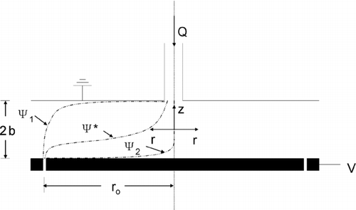
Shown in is the simplified aerosol precipitator geometry used for model development. Only the top flow chamber of the prototype device is considered. Cylindrical coordinates are used, with r and z denoting the radial and axial coordinates, respectively. Neglecting particle inertial and Brownian motion, the particle trajectories are governed by the following equations:
FIG. 6 Illustration of the top flow chamber to be modeled in the prototype precipitator, where charged particles are precipitated when an electrical field is established.
CitationKnutson and Whitby (1975) showed that non-diffusive particles would traverse their similar device along trajectories of constant particle stream function,
The limiting streamlines, ψ1 and ψ2 (shown in ) form two boundaries which contain the entire volumetric aerosol flow in the mini-disk precipitator. The volumetric flow rate, Q can be expressed by,
Assume that the particle concentration profile at the aerosol entrance is uniformly distributed between two limiting streamlines. When a voltage is applied to the middle disk, the resulting electrical field deflects the charged particles toward the top grounded plate. From Equation (Equation8),
The condition for particles penetration can be defined by Equation (Equation12),
Substituting Equations (Equation9), (Equation10), and (Equation11) into Equation (Equation12) we conclude that the particle penetration, P, through the disk precipitation zone can be described as,
Note that the particle penetration is independent of the detailed flow profile in the mini-disk precipitator, as long as the flow remains steady and laminar.
The assumptions of a steady, axisymmetric laminar flow and no radial component to the electrical field may not reflect the actual conditions in practice. An empirical coefficient is thus included into Equation (Equation14) to account for the discrepancy between ideal and real conditions:
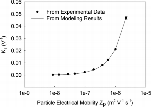
Equation (Equation15) is then used to fit the particle cutoff curves given in , using a single flow chamber for charged particle precipitation. Since the curve for each particle size is linear, the slope, K1, can be retrieved from the experimental data. shows the comparison of the K1 values from both experimental data and the model calculation, as a function of test particle electrical mobility. It is found that the experimental slope, K1, is well fitted with that predicted by the model when the empirical factor,α1, is set as 0.95, indicating the validity of the model as well as its assumptions.
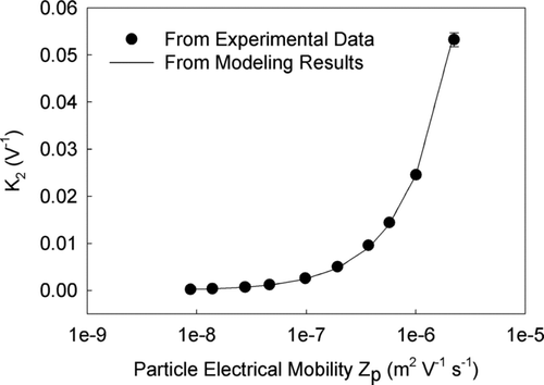
The performance of the prototype when only using the lower chamber for charged particle precipitation had also been investigated in this study. Under such operation the curves of particle penetration v.s. applied voltage at different particle size are again linear. Similar data analysis was also done on the data collected. It has shown that the model agrees well with the experimental data when α1 is set as 1.05.
For operation using dual chamber precipitation, the penetration of charged particles through the device is described as follows, based on the assumption of remixing into a uniform particle distribution in the small orifices between the upper and lower flow chambers:
FIG. 8 Plot of P1/2 v.s. applied voltage for experimental data on the dual chamber precipitation operation (Q = 0.3 lpm).
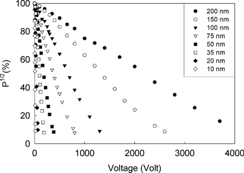
In addition to the advancement of the modeling on the performance of disk-type precipitator, the developed models have two practical applications: one is to use them in the data reduction scheme to recover particle size distribution for any nanoparticle sizer, and the other is to optimize the performance of disk-type precipitator under a variety of physical and space constraints.
5. CONCLUSION
A mini-disk precipitator was designed to serve as an electrostatic aerosol classifier and its performance was experimentally evaluated. This newly designed prototype device provides a low-cost solution for applications needing the spatially distributed measurement or personal exposure monitoring of nanoparticles. Despite its compact size, the prototype device provides satisfactory penetration for charged particles. The design of the device allows it to be operated utilizing one or both flow chambers between the middle disk and top/bottom plates for particle precipitation. Both operations work very well in differentiating particle sizes by electrical mobility. The performance of the precipitator when operated at a fixed flowrate was experimentally characterized by the particle cutoff curves, i.e., the penetration v.s. applied voltage. Semi-empirical models were also developed to describe the particle cutoff curves for both operational conditions. Dual chamber precipitation is preferred because the arrangement reduces the voltage requirement to remove all particles of a given electrical mobility. The particle cutoff curves under such an operation are not strictly linear. Our modeling results indicate that the nonlinearity is probably a result of the aerosol mixing and redistribution when it moves between the flow chambers.
The authors are grateful for the manufacture and financial support provided by the NASA Glenn Research Center under Research Grant NAG3-2625.
REFERENCES
- Adachi , M. , Liu , B. Y. H. and Pui , D. Y. H. 1991 . Development of an Automatic System for Measuring Particle Charge and Size Distribution in a Clean Room. . Part. Part. Syst. Charact. , 8 : 200 – 208 .
- Biswas , P. and Wu , C. Y. 2005 . Nanoparticles and the Environment. . J. Air & Waste Manage. Assoc. , 55 : 708 – 746 .
- Chen , C. C. , Huang , S. H. , Lin , W. Y. , Shih , T. S. and Jeng , F. T. 1999 . The Virtual Cyclone as a Personal Respirable Sampler. . Aerosol Sci. Technol. , 31 : 422 – 432 .
- Forsyth , B. , Liu , B. Y. H. and Romay , F. J. 1998 . Particle Charge Distribution Measurement for Commonly Generated Laboratory Aerosols. . Aerosol Sci. Technol. , 28 : 489 – 501 .
- Fujishima , A. , Hashimoto , K. and Watanabe , T. 1997 . TiO2 Photocatalysis: Fundamentals and Applications , BKC, Inc. .
- Hurd , F. K. and Mullins , J. C. 1962 . Aerosol Size Distribution from Ion Mobility. . J. Coll. Sci. , 17 : 91 – 100 .
- Kauppinen , E. I. 1990 . Coal Combustion Aerosols—A Field Study . Environ. Sci. Technol. , 24 : 1811
- Knutson , E. O. and Whitby , K. T. 1975 . Aerosol Classification by Electric Mobility: Apparatus, Theory, and Applications. . J. Aerosol Sci. , 6 : 443 – 421 .
- Koch , W. , Dunkhorst , W. and Lodding , H. 1999 . Design and Performance of a New Personal Aerosol Monitor. . Aerosol Sci. Technol. , 31 : 231 – 246 .
- Lee , S. J. , Demokritou , P. , Koutrakis , P. and Delgado-Saborit , J. M. 2006 . Development and Evaluation of Personal Respirable Particulate Sampler (PRPS). . Atmos. Environ. , 40 : 212 – 224 .
- Liu , B. Y. H. and Pui , D. Y. H. 1974 . A Submicrion Aerosol Standard and the Primary, Absolute Calibration of the Condensation Nuclei Counter . J. Coll. Interface Sci. , 47 : 155
- Liu , B. Y. H. , Whitby , K. T. and Pui , D. Y. H. 1974 . A Portable Electrical Analyzer for Size Distribution Measurement of Submicron Aerosols . J. Air Poll. Control Assoc. , 24 ( 11 ) : 1067 – 1074 .
- Liu , L.-J. , Slaughter , J. C. and Larson , T. V. 2002 . Comparison of Light Scattering Devices and Impactors for Particulate Measurements in Indoor, Outdoor, and Personal Environments. . Environ. Sci. Technol. , 36 : 2977 – 2986 .
- Mader , B. T. , Flagan , R. C. and Seinfeld , J. H. 2001 . Sampling Atmospheric Carbonaceous Aerosols Using a Particle Trap Impactor/Denuder Sampler . . Environ. Sci. Technol. , 35 : 4857 – 4867 .
- Maynard , A. D. and Kuempel , E. D. 2005 . Airborne Nanostructured Particles and Occupational Health. . J. Nanopart. Res. , 7 : 587 – 614 .
- Misra , C. , Singh , M. , Shen , S. , Sioutas , C. and Hall , P. M. 2002 . Development and Evaluation of a Personal Cascade Impactor Sampler (PCIS). . J. Aerosol Sci. , 33 : 1027 – 1047 .
- Oberdörster , G. , Oberdörster , E. and Oberdörster , J. 2005 . Nanotoxicology: An Emerging Discipline Evolving from Studies of Ultrafine Particles . Environ. Health Perspect. , 113 ( 7 ) : 823 – 839 .
- Scheibel , H. G. and Porstendörfer , J. 1983 . Generation of Monodisperse Ag- and NaCl-Aerosol with Particle Diameters between 2 and 300 nm . J. Aerosol Sci. , 14 : 113 – 126 .
- Wang , S. C. and Flagan , R. C. 1990 . Scanning Electrical Mobility Spectrometer. . Aerosol Sci. Technol. , 13 : 230 – 240 .
- Warheit , D. B. 2004 . Nanoparticles: Health Impacts. . Materials Today , 7 : 32 – 35 .
