Abstract
A convenient way to synthesize aluminum nanoparticles is to evaporate the metal, direct this vapor into a tubular reactor and quench it with a radial flow of cold gas. The supersaturated vapors nucleate and grow into the desired nanoparticles. For small-scale operations, because of the high temperatures and relatively low flow rates involved, the conditions of operation are usually laminar. As the units are scaled up to higher production rates, the flows become transitional or even fully turbulent. This work reports on the use of a Low Reynolds Number (LRN) turbulent model to simulate this system and its scale up for the synthesis of pure aluminum powders. Coagulation was identified as the dominating mechanism in particle growth for the conditions and scales studied. Scale up with dynamic similitude results in increased residence time which significantly changes the particle properties during scale-up. In scale-up with constant residence time, the flow field regime changes from laminar to turbulent. These changes in the flow regime affect the particle characteristics significantly for reactors of small length to diameter ratio (L/D = 6), but are almost insignificant for large length to diameter ratios (L/D = 12). Turbulent reactors showed small changes in the particle characteristics, plus a better percentage of metal vapor recuperated as particles at the end of the reactor.
NOMENCLATURE
| D m | = |
reactor diameter |
| d p m | = |
particle diameter |
| d pg m | = |
geometric mean diameter |
| L m | = |
reactor length |
| N 1/m3 | = |
particle concentration |
| Q m3/s | = |
initial volumetric flow rate |
| Re | = |
Reynolds number |
| S | = |
scaling factor |
|
| = |
residence time in reactor |
| T K | = |
temperature |
| V m3 | = |
reactor volume |
| W m | = |
Injection slot width |
| σ g — | = |
geometric standard deviation |
1. INTRODUCTION
The unique properties associated with nanosize metal particles, which are due to the high fraction of atoms that reside at the grain boundaries, make them very attractive for different applications such as super alloys, thick film conductors, catalysis for the chemical industry, coatings, and others (CitationKear and Skandan 1999). A common method of producing metal nanopowders is the Inert Gas Condensation (IGC) process, where particles are produced when hot metal vapor is quenched with a cold inert gas. Pure product due to the inert atmosphere, relative ease of control by adjusting operation parameters, and possible continuous operation are the main features that make the IGC method appropriate for the production of aluminum nanoparticles (CitationKruis et al. 1998).
The increasing interest in commercial applications of nanomaterials puts pressure on the nanopowders manufacturing industry to increase production rates while keeping particle characteristics within desired limits. The question of how to scale-up the current process to the required production rates and the impact of such on powder characteristics has recently been attracting the attention of the scientific community (CitationWegner and Pratsinis 2003; CitationWegner and Pratsinis 2005; CitationMarchisio et al. 2006). The objective of the present work is to give a first estimation of the effects of two different scale-up practices (i.e., dynamic similitude and constant residence time) on the particle characteristics. The approach taken was to use a mathematical model to describe the main phenomena in the nanoparticle production process.
A two dimensional axi-symmetric turbulent model of a particle generator (or reactor) with radial injection of a quenching gas was used to gain a better understanding of the particle forming process using the Inert Gas Condensation method (CitationAristizabal et al. 2006). (Although the particle generator is not in this instance a true reactor, similar vessels have been used in our laboratories to synthesize nanoparticles using chemical reaction rather than only condensation so we use the term reactor by analogy.) The model uses the Jones-Launder Low Reynolds Number (LRN) Turbulence model to calculate the fluid flow field (CitationJones and Launder 1972) coupled to the energy equation and the conservation of metal vapor. The evolution of the particle size distribution is calculated using the method of moments (MOM) assuming a lognormal particle size distribution (CitationPratsinis and Kim 1989; Girshick el al. 1992). The model considers three mechanisms that shape the particle size distribution; they are: nucleation, condensation, and coagulation. Particle nucleation was modeled using the self-consistent nucleation rate (CitationGirshick 1991), while condensation of metal vapor on existing particles is governed by molecular bombardment, and the coagulation of particles takes place in the free-molecular regime. Furthermore, particles are transported by convection, Brownian diffusion, and thermophoresis.
At temperatures lower than the aluminum melting point, the particles were treated as rigid spheres with no coalescence or agglomeration. This may underestimate growth at low temperatures. Furthermore, the model does not consider particle evaporation; therefore particles are allowed in zones where the metal vapor saturation ratio is below one. The volume of particles that exist in low saturation zones is smaller than 0.5% of the total metal condensed, thus omitting the particle evaporation in the model is expected to have only a small influence in the calculations. Finally, the conservation equations were discretized using the Finite Volume Finite Difference Method (FVFDM). The SIMPLER method (Semi-Implicit Method for Pressure-Linked-Equations Revised) was used (CitationPatankar 1980) to solve for the fluid flow.
The model provides information on the spatial distributions of velocities, temperature, metal vapor concentration, and particle size distribution characteristics within the reactor (i.e., particle number concentration, geometric mean diameter, and geometric standard deviation). The particle size distribution characteristics are calculated from the first three moments of the number distribution. Finally, mixing cup averages are calculated from the 2D axi-symmetric results.
Due to the large amount of data generated in this scale-up study, it is impossible to include all the profiles in the discussion. Even though the spatial distribution information is important to understand the changes in the particle characteristics with scale-up, from a production point of view it is the final product that matters the most. Mixing cup averages represent the final product powder characteristics assuming that the product is collected over the entire cross sectional area at the end of the reactor. The scale-up results presented here use mixing cup averages, however, the analysis and interpretation was done considering the spatial distribution of the different variables.
A detailed description of the mathematical equations, boundary conditions, and solution methodology used is presented in CitationAristizabal et al. (2006). In this publication the 2D profiles for turbulent viscosity, temperature, metal vapor concentration, particle number concentration, particle geometric mean diameter, and the geometric standard deviation are discussed in detail. For instance, it was found that depending on the strength of the quenching jet, the particle generator operates in the laminar or the turbulent regime. Also, a recirculation zone after the injection was identified. This recirculation zone extends for longer distances for laminar compared to turbulent conditions, explaining the differences in particle characteristics in the transition regime. Furthermore, for the particular set of boundary conditions studied two nucleation spots were identified, one at the entrance of the reactor where the hot vapor is rapidly cooled by the wall, and the second one at the injection where the main flow is mixed with the quenching jet. The relative strength of these nucleation spots was found to be important in explaining the changes in the particle characteristics estimated by the model.
It is customary to use the principle of similarity to assist the scale-up of a process. This principle involves maintaining the dimensionless groups characterizing the phenomena of interest constant from the smaller to the larger scale of equipment. However, for complex systems where several dimensionless numbers should be considered, maintaining all of them constant is impossible. Two systems are said to be geometrically similar when the ratios of corresponding dimensions in one system are equal to those in the other. Hence, geometrical similarity exists between two pieces of equipment of different sizes when both have the same shape. Kinematic similarity exists between two systems of different size when they are not only geometrically similar but when the ratios of velocities between corresponding points in each system are also the same. Dynamic similarity exists between two systems when, in addition to being geometrically and kinematically similar, the ratio of forces between corresponding points in each system are equal (CitationBisio and Kabel 1985). Two different types of scale-up are examined in the present article. The first compares reactors having the same flow regime but different residence times while the second compares reactors having the same residence time but necessarily different flow regimes (Reynolds number). Both treatments start with the base case discussed in the previous publication (CitationAristizabal et al. 2006) and assume that process scale-up is as a single reactor.
2. REACTOR AND BASE CONDITIONS
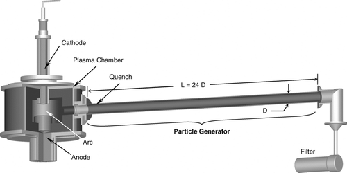
shows a schematic drawing of the process, the plasma metal vapor generating chamber and the particle generator. The particles are collected at the end of the particle generator by a filter. It is assumed that the particles are only formed inside the particle generator. For the base case, the particle generator is 60 cm in length and 5 cm in diameter. The quenching gas is injected through a circumferential slot 0.25 mm wide, located 5 cm from the entrance. The model has been developed for dilute systems, where the concentration of metal vapor in the gas phase is small (∼ 10−3 kg Al/kg gas). The properties of the metal vapor and carrier gas mixture are assumed those of the carrier gas (CitationAristizabal et al. 2006). Because the system is very dilute, no heats of condensation or vaporization are considered. The base case parameters are summarized in . The mathematical model used in this work only describes the phenomena taking place inside the particle generator. Although the scale-up of the heat source (i.e., transferred arc plasma shown in ) is also of great interest, it is outside of the scope of this work.
TABLE 1 Base case parameters
Inside the particle generator the predicted flow is a mixture of laminar and turbulent regimes as shown in . In this figure, the turbulent viscosity is compared with the gas viscosity. When the turbulent viscosity is at least one order of magnitude greater than the gas viscosity the flow is considered turbulent. Similarly, when the gas viscosity is at least ten times greater than the turbulent viscosity the flow is considered laminar. When the magnitude of both viscosities is comparable, the flow is considered to be in transition. Because of the boundary conditions chosen (), shows that the flow entering the reactor is in the transition zone. However, the flow close to the wall changes to laminar because of the rapid decrease of fluid velocity near the wall. Once it reaches the injection point, the jet induces the transition to turbulence. The turbulent zone in the second part of the reactor occupies almost the entire reactor with a small transition zone near the wall, and a very small laminar sublayer.
FIG. 2 Laminar, transition and turbulent zones inside the reactor for the base case operating conditions in .
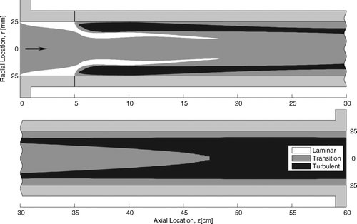
By comparing the nucleation, condensation, and coagulation rates of the moment conservation equations it is possible to determine the zones inside the reactor where one rate dominates over the others. Nucleation takes place in two different spots, one at the entrance and the second at the injection point. Only the much larger nucleation zone is identified in . Both nucleation spots occur at places of steep temperature drops where the saturation ratio increases significantly favoring nucleation. Condensation on the other hand, dominates in the zones where temperature gradients are less steep and the saturation ratio slowly increases above one. The recirculation zone after the injection is dominated by condensation because of the large number of particles generated at the injection and the assumption in the model that at low temperatures coagulation stops. Coagulation dominates the rest of the reactor where particles exist and the metal vapor has been depleted. Although not shown in , coagulation dominates most of the second half of the reactor.
3. EFFECT OF THE MEAN RESIDENCE TIME
The first approach to scale the process maintains geometrical similitude (Equation [Equation1]), and constant Reynolds number (Equation [Equation2]). Because body forces such as gravity have been neglected, the constant Reynolds number constraint can be regarded as a dynamic similitude condition. Combining these two equations and using the definition of the Reynolds number it is possible to obtain an expression for the scale factor, S (ratio of the large (2) production rate to the small (1) production rate) in terms of the dimensions of the two systems (Equation [Equation3]). The mean residence time or space time can be defined by the ratio of the volume of the reactor to the volumetric flow rate, which in this case is the sum of both the main flow and the quench injection. One of the main disadvantages of using constant Reynolds number is that the mean residence time of the reactor cannot be maintained constant; it changes with the scale factor (Equation [Equation4]). The simulation conditions are as reported for the base case of but are modified according to the scale-up equations (Equations [Equation1], [Equation2], [Equation3]). The results are presented with a parameter of interest as the ordinate, the reactor diameter and scale factor as the abscissas, and the reactor length as a second variable.
presents the change in the particle number exit concentration in terms of the diameter of the reactor for different reactor aspect ratios. The concentration decreases as the reactor length increases at the same diameter and decreases by about three orders of magnitude as the reactor is scaled-up by a factor of 16, i.e., from 1/2 the base case to 8 times the base case. As shown by Equation (Equation3), the mean residence time increases as the square of the reactor diameter, thus the time that the particles have to be formed by nucleation, coagulation, and condensation is much longer for bigger reactors. Keeping this in mind, it is possible to analyze the dependence of the product characteristics with respect to the size of the reactor by considering the effect of increasing or decreasing the mean residence time of the reactor on the different processes that modify the particle size distribution. Also, for the flow conditions studied (i.e., 60% injection) the particle generator operates in the turbulent regime as described by CitationAristizabal et al. (2006).
FIG. 4 Mixing cup particle number concentration as a function of the reactor diameter—Constant Reynolds number.
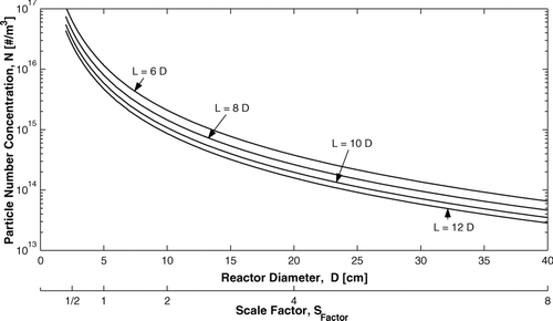
Particle growth is mainly driven by coagulation when high quenching rates are used because of the high particle concentrations normally associated with this process. At first sight, the decrease in the particle number concentration presented in seems to indicate that the improved coagulation due to longer residence times is responsible for this decrease. However, condensation also plays an important role in this decrease in particle concentration. As the reactor size increases the total number of particles nucleated decreases due to nucleation suppression by condensation; as explained in the following paragraph.
Nucleation and condensation are both responsible for gas-to-particle conversion; they compete for the available metal in the gas phase to form condensed matter. At first, nucleation is responsible for particle formation. However as the concentration of particles increases the available surface area for condensation also increases, thus increasing the condensation rate. Once the condensation rate is significantly higher than the rate of nucleation it is said that the nucleation is suppressed by condensation, and the available metal in the gas phase preferably condenses on existing particles rather than forming new ones. The effect of nucleation suppression becomes increasingly important with scale-up, because the nucleation length scale (i.e., critical particle diameter) does not scale directly with reactor size. Thus, nucleation suppression and longer time for coagulation are the reasons for the decrease in particle number concentration as the reactor size increases as shown in .
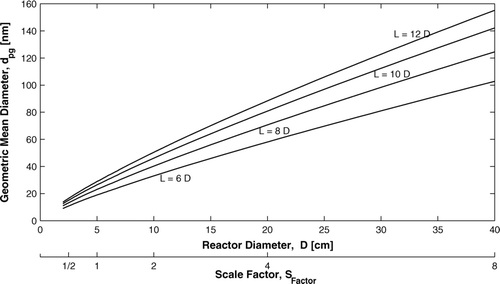
Even though the effect of condensation over nucleation increases as the size of the reactor increases, the main mechanism responsible for particle growth is still coagulation of particles. Coagulation of particles has two major impacts on the characteristics of the final product. It decreases the particle concentration and increases their size. This increase in the particle diameter as the mean residence time increases (as a consequence of the increasing size of the reactor) can be seen in . For a given aspect ratio, the increase is almost linear with the increase in the reactor diameter. As the reactor size decreases, the particle size decreases towards the critical size. The analysis of reactors larger than presented here is not possible with the present model, because the Knudsen number of the particles starts to move into the continuum regime, while the present model is limited to the free molecular regime.
FIG. 5 Mixing cup geometric mean diameter as a function of the reactor diameter—Constant Reynolds number.
The spread of particle size is also affected by changes in the mean residence time. It would be expected that as the mean residence time increases the geometric standard deviation should approximate that of the asymptotic value for coagulating aerosols in the free molecular regime, 1.355 (Lee et al. 1984); this is not observed. shows the change in the geometric standard deviation with scale-up. As the size of the reactor increases, the geometric standard deviation also increases. The decrease in the particle number concentration and the limitation of the present model to a single mode are responsible for this increase in the geometric standard deviation estimated by the model. As the size of the reactor increases, the concentration of particles decreases due to suppressed nucleation. Thus the expected increase in coagulation due to increased residence time is attenuated by the decrease in particle concentration. The geometric standard deviation for a given reactor diameter decreases as the length of the reactor increases showing the expected effect of coagulation.
FIG. 6 Mixing cup geometric standard deviation as a function of the reactor diameter—Constant Reynolds number.
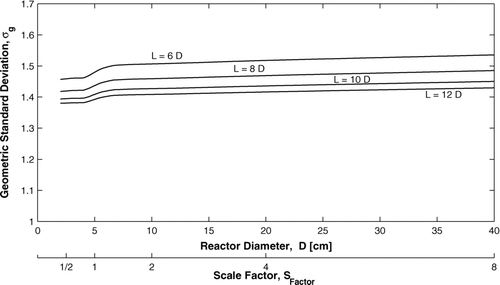
It is also important to note that nucleation takes place in two different spots in the reactor. At the entrance the cold wall induces a first nucleation spot, while the second one takes place at the quenching gas injection. When the mean residence time is small, particles generated at the first spot will reach the injection nucleation spot with a mean geometric diameter close to the critical size. The formation of new particles at the quench injection will not increase the standard deviation significantly. However, when the mean residence time is larger, the particles generated at the entrance grow before reaching the quench injection location, where particles of critical size are formed; thus the geometric standard deviation is significantly increased since the bimodal distribution actually formed is being represented by a mono-modal distribution with a high standard deviation. This may be observed at a reactor diameter of about 5 cm in . As the size of the reactor increases the standard deviation after the injection nucleation spot increases. Since broader particle distributions take longer to reach the coagulation asymptotic value (CitationLee et al. 1984), the geometric standard deviation at the end of the reactor increases as the size of the reactor increases.
4. EFFECT OF FLOW REGIME
Scale up maintaining constant Reynolds number is a common practice for applications where the fluid flow plays a paramount role in the process (laminar heat exchangers, for example). However, reacting flows are normally scaled by using constant residence time instead (CitationBisio and Kabel 1985). The effect of changing the mean residence time of the reactor has been shown to change the characteristics of the particles; therefore a better approach would be to maintain the mean residence time constant in the scaling process (Equation [Equation5]), while allowing other parameters such as the main and injection flow rates (Equation [Equation6]) to change. Note that since the Reynolds number also changes with the scaling factor (Equation [Equation7]), the reactor may change from the laminar to the turbulent regime as it is scaled up. The base case presented in has been modified to study the case where flow transition occurs during scale-up. The injection flow rate was decreased from 60 slpm to 20 slpm (i.e., 60% to 20%) to ensure that the base case lies in the laminar operating region (CitationAristizabal et al. 2006).
This change in the flow regime with scale-up (at constant residence time) can be seen in , where the mixing cup temperature is presented as a function of the diameter of the reactor for different axial positions. The presence of three different zones can be clearly seen. For small diameters, the Reynolds number of the reactor is small. It increases with the scale factor, as shown in Equation (Equation7). Note that the term laminar does not indicate that the flow is laminar inside the entire reactor. Instead it indicates that the quench injection jet, which is responsible for the abrupt changes in the flow field, remains laminar. The turbulent zone, on the other hand, refers to the introduction of turbulence by the jet. For both the laminar and turbulent zones some parts of the reactor, particularly the end of the reactor, are affected by turbulence since the decrease in temperature (decrease in viscosity) along the reactor increases the local Reynolds number. The double solution for the “transition” zone was obtained by a zero order continuation (i.e., use of a previous solution as initial guess for the new set of conditions). The arrows in the graph indicate the direction of continuation, i.e., whether the solution comes from the direction of increasing or decreasing diameters. When the solution is calculated in the direction of increasing scale factors, the solution tends to remain laminar (upper curve), while it remains turbulent (lower curve) when the continuation is done in the other direction.
FIG. 7 Mixing cup temperature as a function of the reactor diameter for different reactor length to diameter ratios—Constant mean residence time and 20% injection.
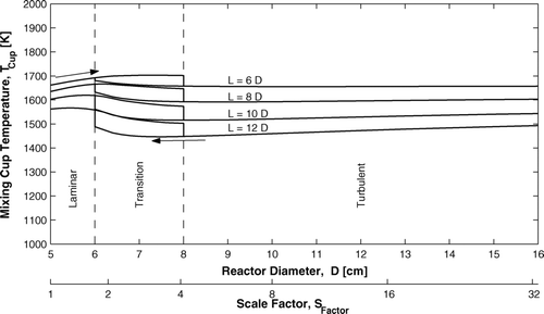
It may be seen from , that as the diameter of the reactor increases, the flow field changes from laminar to turbulent, probably affecting the characteristics of the particles. In the scale-up process presented here, the mean residence time has been maintained constant. Therefore it would be expected that the properties of the particles remain unchanged with the change in size of the reactor, and be only affected by changes in the flow and temperature fields.
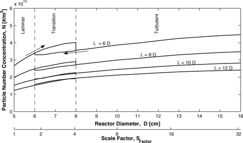
shows the effect of changes in the flow regime on the particle number concentration for reactors of different diameters and lengths. Note that the particle number concentration is significantly affected in the transition regime for short reactors. The concentration is higher for laminar behavior and lower for turbulent behavior. The magnitude of this effect decreases with increasing reactor length and essentially vanishes for L ≥ 10D. The main reason for the differences between these two solutions is the enlargement of the recirculation zone after the injection for the laminar case. This zone is at a temperature lower than the melting point of aluminum, thus particle coagulation and sintering stop (assumption of the model) decreasing the time particles have to coagulate inside the particle generator. A second important observation is that when the reactors are entirely in the turbulent regime, there is relatively little change in particle concentration as the reactor size increases, as expected since the mean residence time is held constant and the flow field changes very little.
FIG. 8 Mixing cup particle number concentration as a function of the reactor diameter for different reactor length to diameter ratios—Constant mean residence time and 20% injection.
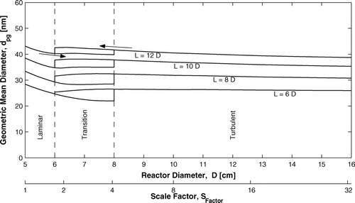
shows the effect of scale-up on the particle geometric mean diameter. Within a regime, the size decreases as the reactor diameter increases and increases as the reactor length increases. Within the transition zone, larger particles are predicted for turbulent behaviour, primarily due to longer coagulation times because of the shorter recirculation zone. The overall effect of the transition is less for longer reactors. Finally, within the turbulent regime, the particle size changes very little as the reactor is increased in size from a scale factor of four to a scale factor of 32.
FIG. 9 Mixing cup geometric mean diameter as a function of the reactor diameter for different reactor length to diameter ratios—Constant mean residence time and 20% injection.
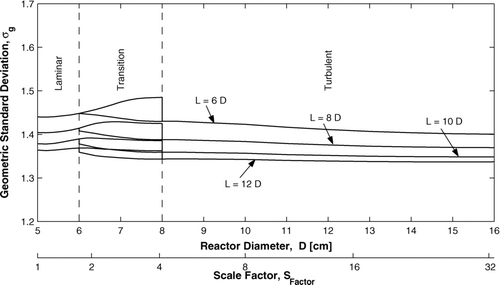
The geometric standard deviation is also affected by changes in the flow regime as is shown in . Within the laminar regime, the geometric standard deviation increases as the reactor is scaled up and decreases as the reactor length increases. The increase with scale is closely related to the enlargement of the recirculation zone in the laminar regime and the reduced coagulation time associated with it. Similarly, within the transition zone, higher standard deviations are observed for the laminar continuations. As in the particle concentration and size, the importance of the transition zone decreases as the reactor length increases, since the importance of the recirculation zone enlargement decreases as the reactor length increases and coagulation drives the standard deviation towards the asymptotic value. Finally, in the turbulent regime, the standard deviation decreases slowly as the reactor scale factor increases and decreases as the reactor length increases. As the reactor is scaled-up in the turbulent regime, the jet is capable of penetrating deeper into the main flow producing more particles, thus increasing the coagulation rate and speeding up the process to reaching the asymptotic value.
FIG. 10 Mixing cup geometric standard deviations a function of the reactor diameter for different reactor length to diameter ratios—Constant mean residence time and 20% injection.
It is also important to examine the behaviour of condensed material as the flow regime changes from laminar to turbulent due to scale-up. For a reactor with L = 12D, shows the distribution of metal reaching the end the reactor as particles and vapor, as well as the amount of metal lost from the flowing gas stream by different mechanisms. It is seen that the conversion of inlet vapor to particles increases from about 75% to almost 90% as the reactor is scaled up by a factor of 32 at constant residence time; most of the increase occurs during the transition from the laminar to the turbulent regime. The increase in conversion to particles is primarily because more of the metal vapor is condensed.
FIG. 11 Percentage metal losses and metal percentage from the input as a function of the reactor diameter—Constant mean residence time and 20% injection.
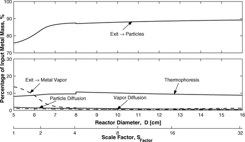
The losses to the reactor walls are little affected by the changes in flow regime during scale-up. The thermophoretic effect, i.e., the transfer of particles to the walls by temperature differences, represents the greatest loss of metal. It remains almost constant at about 10% of the total input of metal. It is slightly affected by the change in the flow regime, since the temperature distribution inside the reactor also changes. Particle and vapor diffusion to the wall are almost negligible for the range of reactor sizes studied; they each represent about a 2% loss of the total mass. It is important to note that since the reactor wall operates at above the melting point of the metal, the “losses” to the wall can in principle be recycled. The cost to the process of this recycling is in the energy and capital cost of the equipment but not the raw material cost of the feed material.
An overview of the results of the scale-up keeping residence times constant suggests the following strategy. The base case should be chosen to fall within the turbulent regime and to give the particle diameter desired in the process. The reactor operating conditions and product characteristics are then relatively insensitive to the reactor size. The efficiency of conversion of metal vapour to particle product increase as the reactor diameter increases.
5. CONCLUSIONS
A previously described model for the production of ultrafine aluminum powder has been used to examine scale-up of the process (CitationAristizabal et al. 2006). Scale-up under conditions of constant flow regime and constant residence time were examined separately. Coagulation was identified as the dominating mechanism in particle growth for the conditions and scales considered. The study was limited to ranges where the product particles remain in the free molecular regime.
Scale-up at constant Reynolds number with geometric similitude, to have dynamic similitude between the small and large scale results in increased mean residence time which significantly changes the particle properties during scale-up. As the size of the reactor is increased, the particle number concentration decreases due to nucleation suppression. The particle geometric mean diameter increases almost linearly with the size of the reactor, mainly due to the decrease in particle number. Therefore condensation generates larger particles that grow even larger by coagulation. The geometric standard deviation is almost constant showing a slight, but unexpected, increase with increasing reactor size. This was attributed to the decrease in the coagulation rate due to the decrease in the particle number concentration. Since the Reynolds number is maintained constant there is no change in the turbulent flow regime as the reactor is scaled.
In scale-up with constant residence time, the flow field regime changes from laminar to turbulent. These changes in the flow regime affect the particle characteristics significantly for reactors of small length to diameter ratio (L/D = 6), but are almost insignificant for large length to diameter ratios (L/D = 12). Turbulent reactors showed small changes in the particle characteristics, plus a better percentage of metal vapour recuperated as particles at the end of the reactor, indicating that it would be recommended to operate in this regime.
Financial support from the Natural Sciences and Engineering Research Council of Canada is gratefully acknowledged.
REFERENCES
- Aristizabal , F. , Munz , R. J. and Berk , D. 2006 . Modeling of the Production of Ultra Fine Aluminum Particles in Rapid Quenching Turbulent Flow . J. Aerosol Sci , 37 : 162 – 186 .
- Bisio , A. and Kabel , R. L. 1985 . Scaleup of Chemical Processes , New York : Wiley .
- Girshick , S. L. 1991 . Comment on: Self-Consistency Correction to Homogeneous Nucleation Theory . J. Chem. Phys. , 94 : 826 – 827 .
- Girshick , S. L. , Chiu , C. P. , Muno , R. , Wu , C. Y. , Yang , L. , Singh , S. K. and McMurry , P. H. 1993 . Thermal Plasma Synthesis of Ultrafine Iron Particles . J. Aerosol Sci , 24 : 367 – 82 .
- Jones , W. P. and Launder , B. E. 1972 . The Prediction of Laminarization with a Two-Equation Model of Turbulence . Int. J. Heat Mass Transfer , 15 : 301 – 314 .
- Kear , B. H. and Skandan , G. 1999 . Overview: Status and Current Developments in Nanomaterials . Int. J. Powder Metall , 35 : 35 – 37 .
- Kruis , F. E. , Fissan , H. and Peled , A. 1998 . Synthesis of Nanoparticles in the Gas Phase for Electronic, Optical and Magnetic Applications—A Review . J. Aerosol Sci , 29 : 511 – 535 .
- Lee , K. W. , Chen , H. and Gieseke , J. A. 1984 . Log-Normally Preserving Size Distribution for Brownian Coagulation in the Free-Molecule Regime . Aerosol Sci. Technol , 3 : 53 – 62 .
- Marchisio , D. L. , Rivautella , L. and Barresi , A. 2006 . Design and Scale-Up of Chemical Reactors for Nanoparticle Precipitation . AIChE J. , 52 : 1877 – 1887 .
- Patankar , S. V. 1980 . Numerical Heat Transfer and Fluid Flow , New York : Hemisphere Publishing Corporation .
- Pratsinis , S. E. and Kim , K. S. 1989 . Particle Coagulation, Diffusion and Thermophoresis in Laminar Tube Flows . J. Aerosol Sci , 20 : 101 – 111 .
- Wegner , K. and Pratsinis , S. E. 2003 . Scale-up of Nanoparticle Synthesis in Diffusion Flame Reactors . Chem. Eng. Sci , 58 : 4581 – 4589 .
- Wegner , K. and Pratsinis , S. E. 2005 . Gas-phase Synthesis of Nanoparticles: Scale-up and Design of Flame Reactors . Powder Technol , 150 : 117 – 122 .
