Abstract
A stochastic model for the motion of a particle initially at rest on a surface is explored. Fluid and adhesive forces are quantified based on first principles, and turbulent fluctuations are addressed probabilistically from probability distribution functions. A Monte Carlo process yields the distributions of particle position and velocity under a wide range of wind conditions and soil sizes. Results indicate that particle size and friction velocity are the most important factors in determining if a particle will resuspend and in predicting its subsequent motion. Larger wind speeds produce more violent fluctuations, which have a greater effect on small particles than on large particles. A theoretical analysis of the threshold friction velocity supports earlier experimental findings. The aerodynamic lift force cannot be neglected, and the torque exerted on a particle can be important in some cases. Applying the results of this work may contribute to reducing uncertainty in large-scale aerosol models.
INTRODUCTION
The resuspension of crustal material is a major input into global atmospheric models, regional air quality models, and exposure models. However, the upward flux of soil is highly variable and uncertain.
When soil and dust contain toxic chemicals, resuspension can also be a major transport route for pollutants. Soil contaminated with lead, for example, is an important source of airborne lead in southern California (CitationHarris and Davidson 2005; CitationYoung et al. 2002; CitationLankey et al. 1998). It may be that urban soil, which is a known reservoir for lead, poses a significant but as yet unquantified air quality problem in other urban areas as well (CitationLaidlaw et al. 2005).
Early work on resuspended particles was performed by CitationBagnold (1941) and CitationChepil (1945a, Citation1945b), who analyzed soil erosion and the roles of surface creep, saltation, and full suspension. The analyses of Bagnold and Chepil suggested that saltation—the type of movement in which particles stay close to the surface and move in smooth, approximately parabolic trajectories—was the primary mechanism for transferring kinetic energy from wind to surface particles. Originally, it was believed that particles too small to undergo saltation were incapable of being resuspended directly by wind. However, experiments of CitationKjelgaard et al. (2004), CitationBraaten et al. (1990), CitationGarland (1982), and others have shown that direct suspension of particles from turbulent wind activity can occur under some circumstances. Review articles on resuspension have been published by CitationZiskind et al. (1995), CitationNicholson (1988), and CitationSehmel (1980).
Whether or not a particle resuspends depends on the balance of external forces. To achieve an accurate picture of resuspension, an analysis must include the transfer of turbulent wind energy to surface particles. CitationCleaver and Yates (1973) were the first to quantify the impact of wall-induced shear on particle resuspension. They inferred that viscous forces give rise to lift, drag, and torque, all of which affect a particle on a surface. Cleaver and Yates's hypothesis, that coherent structures near the wall contribute considerably to the observed particle resuspension, has since been corroborated both by experiments (e.g., CitationKaftori et al., 1995; CitationRashidi et al., 1990; CitationBraaten et al., 1990; CitationYung et al., 1989) and theoretical calculations (e.g., CitationSoltani and Ahmadi 1995a; CitationPedinotti et al. 1992; CitationWen and Kasper 1989).
Despite the extensive resuspension modeling that has occurred, there is still a significant lack of information about the path of a particle very close to the surface. Considerable uncertainty also exists about how coherent structures near the wall affect this process. The knowledge of particle adhesion is similarly inadequate; this is often an empirical or assumed value in resuspension models in contrast to the extensive knowledge of capillary, van der Waals, and electrostatic forces.
For this study we built a model for the resuspension of a single particle based on first principles. The primary goals of this work were to improve our understanding of the impact of turbulent wind fluctuations on resuspension, examine the threshold value for the friction velocity, determine the primary aerodynamic forces responsible for initiating particle motion, and make quantitative predictions for the motion of a soil particle over a range of soil and meteorological parameters.
METHODS
We have built a model that describes the resuspension of a single particle initially at rest by analyzing the external forces exerted on the particle. Forces considered here are derived from wind (lift, drag), molecular interactions (van der Waals), soil moisture (capillary), and gravity. Each is considered in succession below and is used to determine the particle trajectory under turbulent flow conditions. The model helps identify the physical nature of particle resuspension and can serve as the basis for future resuspension flux models. A schematic of our modeling domain is shown in .
FIG. 1 Force balance acting on a single soil particle subject to aerodynamic and adhesive forces (adapted from CitationGreeley and Iversen, 1985).
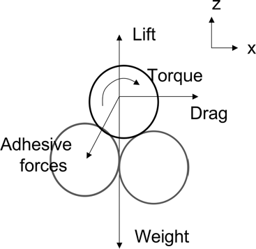
We approach this in a two-dimensional framework, where the mean wind flows in the x-direction and where the z-direction is perpendicular to the surface. Particles are assumed to be spherical with uniform density.
Aerodynamic Lift Force
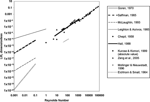
The lift on a small particle is extremely difficult to calculate particularly in turbulent flow. A number of studies have described quantitatively the lift on a rigid sphere in creeping flow where the Reynolds number ≪1 (CitationAsmolov 1999; CitationMcLaughlin 1993; CitationLeighton and Acrivos 1985; CitationGoren 1970; CitationHarper and Chang 1968; CitationSaffman 1965). However, there is significant disagreement among these authors about the magnitude of the lift coefficient, as shown in . Throughout this paper we are referring to the Reynolds number, Re, defined as Dp u∞ /2 ν where D p is the diameter of the particle, u∞ is the free stream velocity, and ν is the kinematic viscosity taken here to be 1.47 × 10⁻⁵ m2 s− 1. For the situations we are modeling, typical of wind blown soil grains, flows are in the moderate (Re ∼ 1–200) flow regime for which there are even fewer theoretical attempts to estimate the magnitude of the lift force.
FIG. 2 The lift force acting on a non-rotating particle over a range of Reynolds numbers. The lift force has been non-dimensionalized as FL|*bsup*| + |*esup*| = FL/ν | *bsup*| 2| *esup*| ρ where FL| *bsup*| +| *esup*| is the dimensionless lift force, FL is the dimensional lift force, and ρ is the density of the fluid taken here to be 1.225 kg m| *bsup*| -3|*esup*|. Equations for the lift force as functions of Re are represented as lines. Tabular data for the lift force are represented by discrete points.
By definition, the lift force causes a suspended particle to move perpendicular to the direction of mean flow. This occurs as a result of two different processes: a pressure differential or a viscosity induced shearing stress. A pressure differential across a curved streamline exerts a centripetal force that causes particles to migrate in the radial direction towards the outside of the circle. Viscosity in the flow exerts some shearing stress that can also cause particles to cross streamlines. An important additional factor is the presence of a wall: the suspended particle creates a disturbance in the flow field, which then interacts with the wall. This disturbance generates additional inertia that has the net effect of pushing a particle in the direction normal to the wall toward the outer flow (CitationHo and Leal 1974). At high Reynolds numbers inertial forces dominate over viscous forces. Near the wall, viscous forces are more important than inertial forces.
A form of the lift force suggested by dimensional analysis is:
Saffman's lift force shown in is generally regarded as a fundamental result that has been corroborated by a number of experiments and subsequent theoretical estimates. CitationSaffman (1965) used the method of asymptotic expansion to solve the particle equations of motion from the Navier-Stokes equations. This holds for Re ≪ 1 in simple shear flow, i.e., no curvature in the flow field. The lift calculated in linear shear flow has been suggested as a reasonable approximation for the lift on a particle in the region closest to the wall (CitationAsmolov 1999).
Since we are more interested in how particles react in turbulent flow conditions than in creeping flow, we focus on estimates of lift at mid-range to high Reynolds numbers. Several investigators have measured the lift on particles in turbulent flow (CitationMollinger and Nieuwstadt 1996; CitationHall 1988; Eichhorn and Small 1964; CitationChepil 1958). Others have calculated theoretically the lift force on a rigid sphere for intermediate Reynolds numbers (CitationZeng et al. 2005; CitationNiazmand and Renksizbulut 2003; CitationBagchi and Balachander 2002; CitationKurose and Komori 1999; CitationDandy and Dwyer 1990).
From , a surprising number of lift force estimates in the mid-range of Reynolds numbers appear to be continuations of the CitationSaffman (1965) lift on a log-log scale. Furthermore the studies for Re > 1 agree well with one another, considering the amount of uncertainty and variability inherent in near-wall turbulent flows. We look first at the findings of CitationMollinger and Nieuwstadt (1996). Their experiments were performed at 35 ≤ Re ≤ 101 but their results appear to be generalizable over a wide range of Reynolds numbers. For a comparison with a theoretical lift force, we consider the results of CitationZeng et al. (2005).
We focus on these two studies for several reasons. The Mollinger and Nieuwstadt result builds on the very similar, earlier outcome of CitationHall (1988). CitationChepil (1958) performed measurements on rigid hemispheres not spheres. CitationEichhorn and Small (1964) performed their experiments in Poiseuille flow near a curved surface, not near a flat surface, although flow profiles near curved and flat plates are remarkably similar (CitationSabersky et al. 1999, p. 290). Several authors have investigated lift force through computational methods (CitationDandy and Dwyer 1990; CitationKurose and Komori 1999; CitationBagchi and Balachander 2002; CitationNiazmand and Renksizbulut 2003; CitationZeng et al. 2005). Each of these results has a complicated dependence on Reynolds number, and the CitationZeng et al. (2005) result was chosen to minimize computing time.
Mollinger and Nieuwstadt quantify their lift force as:
We use these equations to calculate the lift force in our model, and the Zeng et al. regression fits expected results remarkably well. Using the Zeng et al. regression introduces a 3–37% error depending on the Reynolds number of the flow. This is significant, but comparable in size to the variability in the Mollinger and Nieuwstadt equation.
The forms of the lift equations of CitationSaffman (1965), CitationHo and Leal (1974), and CitationMcLaughlin (1993) imply that the direction of lift—either towards the wall or away from the wall—depends on the magnitude of the particle velocity relative to the undisturbed flow. A particle that is moving faster than the flow will experience a positive lift (moves away from the wall), a particle moving slower than the flow will experience a negative lift (moves toward the wall). CitationDandy and Dwyer (1990) commented that the pressure contribution of the lift could go negative, but the viscous contribution would not. CitationKurose and Komori (1999) observed a lift in the negative direction for Re > ∼ 60 (the absolute values of their estimates are shown in for comparison purposes). However, CitationAsmolov (1999) used Fourier transforms of the horizontal velocity to show that the lift would always be positive even for distances comparable to the large length scale of Kurose and Komori. In an oscillatory flow, CitationFischer et al. (2005) also observed both positive and negative lift in their simulations. CitationZeng et al. (2005) described the contradictory directions by pointing to two competing processes. In the first process, vorticity in the flow is generated by the particles, and this vorticity is broken up by the presence of the wall. The velocity distribution is changed such that the particle is moved away from the wall. In the second process, fluid flow relative to the particle will accelerate faster in the gap between the particle and the wall. The reduced pressure in the space between the particle and the wall produces a “lift” force acting towards the wall according to inviscid theory.
Additional lift is felt by a particle that is rotating in a fluid. This is known as the Magnus or Robins effect. Saltating particles have been observed to rotate between 200 and 1000 revolutions per second (CitationSehmel, 1980), and our calculations show that the Magnus effect contributes significantly to the lift force for friction velocities in excess of about 0.6 m/s. The Magnus lift force can be quantified as follows (CitationTemple 1958):
An additional source of lift is the hydrodynamic or buoyancy force. Our analysis indicates that, within our modeling domain of 0 < Re < 200 and 0.1 < D p < 1000 this component of lift is several orders of magnitude smaller than the forces shown in and the Magnus force.
Aerodynamic Drag Force—Translational
For the translational drag exerted on a particle by the wind, we use the Stokes drag with the CitationZeng et al. (2005) corrections to the drag coefficient for mid-range Reynolds numbers. The Stokes drag force is given by the following equation:
At the low end of the range of the particle sizes we are looking at the slip correction factor that can affect the drag force by up to a factor of three. As with the lift force, the Zeng et al. analysis is based on direct numerical simulation of a rigid sphere translating parallel to a surface. Their drag force calculations were found to match experiments quite well for Reynolds numbers less than 50. The drag coefficient C D is fit to the following equation:
The additional drag force produced by the added or virtual mass and the Basset history integral (CitationClift et al. 1978) were found to be 3–5 orders of magnitude smaller than the Stokes drag and were neglected in this analysis.
Aerodynamic Drag Force—Rotational
In shear flow the drag can exert a torque on a particle. Experimentally it has been observed that a particle begins to roll before it is lifted off the surface (e.g., CitationNiño and Garcia 1998; CitationYung et al. 1989; CitationWilliams 1986), and several studies have conjectured that torque may be responsible for overcoming adhesion (CitationVainshtein et al. 1997; CitationZiskind et al. 1995; CitationSoltani and Ahmadi 1994). Thus torque may be an important but often overlooked component of the equations of motion for a particle at rest on a surface. Note that rolling detachment occurs at much lower shears than sliding detachment (CitationSoltani and Ahmadi 1994) so the latter has no practical importance in this study.
The torque on a particle in shear flow has been quantified in several studies. CitationO'Neill (1968) solved for the exact solution in laminar flow bounded by a wall. CitationTsuji et al. (1985) used a torque quantified by CitationDennis et al. (1980) to verify experimental results. CitationWang (1990) calculated the critical moment required to start a particle in motion. CitationZiskind et al. (1995) modified O'Neill's result by adding fluctuating components in the streamwise and vertical directions to account for the impact of coherent structures in the sublayer. CitationZeng et al. (2005) used direct numerical simulation of a rigid sphere translating parallel to a wall to quantify the moment.
Here we use O'Neill's result since we are interested in situations close to a wall where wind speeds are quite low even in turbulent flow. Since the torque is proportional to windspeed, we allow the input of the turbulent flow field to accommodate turbulent fluctuations and forgo the analysis of turbulent moment components as in CitationZiskind et al. (1995).
The net torque on the particle is taken as:
This equation can be used to find the angular rotation:
The analysis of CitationZeng et al. (2005) indicates that torque is induced when the wall breaks the symmetry of the flow. Their results show that the moment approaches zero as z+ approaches 4 where z+ is the nondimensional distance from the wall (z+ = z u*/ν). We include this boundary condition in the model.
Soil Adhesion Force
Adhesion is defined here to mean any force that acts to draw the particle closer to the surface. The four forces of adhesion considered here are gravity, electrostatic forces, capillary forces, and van der Waals forces (CitationBowling 1988; CitationRanade 1987). Gravity is an important component of adhesion for particles larger than about 50 μ m (CitationMcKenna Neuman 2003; CitationSoltani and Ahmadi 1995b; CitationBowling 1988), and it becomes the dominant adhesion force for particles > 200 μ m (CitationMcKenna Neuman 2003). We include it in the force balance for particles of all sizes since it is mathematically simple and can be important for saltating particles.
Electrostatic forces—notably the electrostatic image force and electrical double layer forces—are important primarily for polymers and for particles larger than 50 μm (CitationBowling 1988; CitationRanade 1987). Electrostatic forces have been noted elsewhere to be negligible compared to capillary and van der Walls forces (CitationLu and Likos 2006). A rigorous, mathematical comparison of the electrostatic forces measured by CitationZheng et al. (2003) for soil grains in a windtunnel to the forces described above indicate that electrostatic forces are consistently five to six orders of magnitude smaller than other forces under consideration. Thus, they are ignored in this analysis.
Estimates of the capillary force tend to be highly empirical and depend significantly on hydraulic properties of the soil, the geometry of soil grains, and the composition of the soil. Predictions of the net capillary force can vary by three orders of magnitude depending on particle shape, moisture content, and surface properties of soil grains (e.g., CitationCornelis et al. 2004; CitationFécan et al. 1999; CitationMcKenna Neuman and Nickling 1989; CitationRanade 1987).
Rainfall and evaporation alter the moisture content of the soil, which in turn affects the magnitude of the capillary force. The time since rainfall is an important factor in resuspension, but its effect is extremely difficult to quantify, and it has been neglected in prior resuspension models.
Water evaporation from soil occurs in three stages after a precipitation event. In the first stage, the rate of evaporation is linear with time and is controlled by atmospheric conditions. During the second stage the rate of evaporation declines rapidly with time and is controlled by the hydraulic properties of the soil. During the third stage the rate of evaporation declines slowly to near zero.
As long as the surface soil is saturated, no resuspension will occur. Thus for our purposes the capillary adhesion during stage I evaporation is effectively infinite. However, it is worth noting that van der Waals forces in saturated soil are virtually zero (CitationLu and Likos 2006). During stage II evaporation, the topmost soil layer dries out considerably and the surface soil has essentially reached its “final” or residual water content, θ r (CitationHillel 1998). In this case, the capillary adhesion is zero by definition. The van der Waals force, however, reaches its upper bound at 0% saturation (CitationLu and Likos 2006), so it must be accounted for. Aside from gravity, van der Waals force is the only source of interparticle adhesion that we account for during stage II evaporation. Thus in the model we assume a binary value for adhesion—either soil is at saturation due to recent precipitation and resuspension cannot occur, or it is at its residual moisture content and van der Waals forces hold the particle to the surface.
The duration of phase I evaporation has been determined in field studies to be anywhere from a few hours to a few days after wetting (e.g., CitationVentura et al. 2006; CitationYanful and Choo 1997; CitationJalota et al. 1988). For systems that are resistant to evaporation such as regions with low temperatures and high relative humidity this is on the order of 8 to 10 days after rain (CitationMiyazaki 2006). Determining this time scale is a complicated function of the atmospheric temperature, temperature gradients in the soil column, the relative humidity of the system, the thermal conductivity of the soil, and the depth of water table. For our purposes it is important only that the system be approaching or near the residual moisture content, i.e., that stage I evaporation is complete.
Van der Waals forces are proportional to the materials' Lifshitz-van der Waals constants and the contact area between the particle and the surface. This is shown in the following formula:
TABLE 1 The Lifshitz-van der Waals constants for lead and common soil minerals (CitationTsai et al., 1991)
Modeling Turbulent Flow
We model the dynamics of the wind in 2-dimensions by treating turbulent fluctuations in the streamwise (x) and wall-normal (z) directions as random variables from bivariate probability distribution functions (pdfs). We use a stochastic, Lagrangian framework in which we calculate the wind flow at the location of a given particle that expands the earlier trajectory modeling of CitationAnderson (1987).
Because we are looking at particles initially on the surface, our analysis must address turbulent bursting and account for the coherent structures that characterize the quasi-laminar sublayer. In this region, although the mean wind velocity is quite low, coherent and interacting vortex structures are generated by the highly sheared, viscous flow. How coherent structures are defined varies somewhat between authors. Here we adopt the quadrant convention (e.g., CitationBrodkey et al. 1974) where the instantaneous velocity dictates how an event is categorized. The four categories are quadrant 1: outward interaction (u′ > 0, w′ > 0); quadrant 2: ejection (u′ < 0, w′ > 0); quadrant 3: inward interaction (u′ < 0, w′ < 0); quadrant 4: sweep (u′ > 0, w′ < 0). u′ is the fluctuating component of the wind in the x direction and w′ is the fluctuating component of the wind in the z direction.
For modeling purposes we divide our analysis of wind velocity into two regions. The first is the thin layer directly above the surface where the mean velocity profile is linear with height known as the viscous sublayer. The second is the remaining region above the sublayer, which includes both the buffer region and the logarithmic layer. The average horizontal velocity as a function of height within the buffer and logarithmic layers is combined into a single equation following the work of CitationWu and Yang (2004). Our analysis shows that the Wu and Yang equation scales very well to the van Driest profile in the buffer layer and is a better match to experimental measurements than either the logarithmic or linear approximations in the buffer region. In both the near-wall and mean flow regimes, the average velocity in the z-direction is assumed to be zero.
The correlation coefficient for u′ and w′ in the sublayer is approximated as −0.45 (CitationNezu 2005; CitationPope 2000; CitationTennekes and Lumley 1972) and –u*2/σuσw above the sublayer (CitationArya 1999). σu and σw are the standard deviations of windspeed in the x and z directions, respectively, and are parameters for the probability distributions. In the sublayer region σu and σw are calculated as follows (CitationWu and Jiang 2007):
In the buffer and logarithmic layers, σ u and σ w are calculated as (CitationArya et al. 1999):
Above the sublayer we use a bivariate normal probability distribution function. This has been shown to produce quite accurate wind fields when compared to experimental results (e.g., CitationFerrero et al. 2000; CitationFlesch and Wilson 1992). Below the sublayer we use the bivariate Gaussian pdf modified by a third order Gram-Charlier expansion to find random, instantaneous values of u' and w' as given by Equation (Equation13). Modifying the bi-Gaussian distribution in this way improves turbulent velocity fluctuation predictions in the sublayer (Wu and Jiang 2006; CitationNakagawa and Nezu 1977). It may be that the Gram-Charlier expansion also helps improve the velocity predictions in the outer flow, although the Gaussian pdf is a good approximation especially at high Reynolds numbers (CitationZhou et al. 2005) and reduces computer run time significantly.
The third and fourth moments (skewness and kurtosis) of the Gram-Charlier distribution account for turbulent bursts and their intermittency (CitationWu and Jiang 2007; CitationWu and Yang 2004; CitationNakagawa and Nezu 1977). These are quantified as follows. For the skewness coefficients we use the following. S u = < u′3 > /σ u 3 = 0.102ln(2u*D p /ν) from CitationWu and Yang (2004). This is comparable to a number of other studies (CitationZhou et al. 2005; CitationNakagawa and Nezu 1977; CitationFrenkiel and Klebanoff 1973). We opt to use the Wu and Yang result since the results of Zhou et al. are presented only graphically, a range of values are listed by Nakagawa and Nezu, and a single experimental value is given by Frenkiel and Klebanoff. Given the range of values our model can process, we chose to use the value of S u that is a function windspeed and particle diameter. S w = < w′3 > /σ w 3 = 0.1 which is approximated from the experiments of CitationZhou et al. (2005), CitationKeirsbulck et al. (2002), and CitationBrodkey et al. (1974).
The flatness or kurtosis appears to be an as yet incompletely defined function of the Reynolds number (CitationKeirsbulck et al. 2002; CitationPope 2000). Some experiments have shown a flatness slightly above or below 3 in the near wall region (CitationWu and Yang 2004; CitationNakagawa and Nezu 1977; CitationFrenkiel and Klebanoff 1973). A value of precisely 3 has been observed in at least one experiment (CitationZhou et al. 2005) and this value has been used in models without significant error (CitationWu and Jiang 2007; CitationArya 1999). Our model uses F u = F w = 3, which corresponds to the kurtosis of a standard Gaussian distribution.
For the diffusion coefficients we use the following: M21 = < u′2w′ > /σ u 2σ w = −0.04 and M12 = < u′w′2 > /σ u σ w 2 = 0.1, both from CitationWu and Jiang (2007), although this agrees with the results of CitationKeirsbulck et al. (2002). Both the diffusion coefficients and the skewness coefficients change sign in the buffer layer (CitationZhou et al. 2005; CitationKeirsbulck et al. 2002; CitationNakagawa and Nezu 1977); however, that does not affect this model since we are assuming a normal Gaussian distribution in the buffer and logarithmic layers. In all cases, the roughness height is taken to be 1.5 D p (CitationNikora et al. 2001). The overall probability distribution function for wind speed in the sublayer g(U, W) is given by (CitationWu and Jiang 2007):
Modeling the Path of a Particle
A Monte Carlo model was developed in Mathematica 5.2 to reproduce the possible paths that a soil particle may follow. The model functions as follows. At time t = 0 randomly generated vertical and horizontal wind velocities are pulled from the probability distributions. Forces exerted by wind of this magnitude are calculated, and a net force is calculated for the soil particle at each time step. The net force in turn is used to determine the instantaneous acceleration of the particle relative to the wind. The instantaneous velocity and position are calculated from time integrals over the acceleration. The mean wind speed is function of particle height, so instantaneous wind speeds are randomly chosen based on the height of the particle in the previous iteration.
This force balance process is performed iteratively using the results of the previous iteration as the initial conditions for the next time step. Time steps have a dimensionless duration of 60ν/u * 2, which is small enough to capture all of the events associated with bursting (Jimenez et al. 2005; Jimenez and Moin 1991). We performed a rigorous comparison of the time step with the Lagrangian timescale, and for the friction velocities under consideration here, the time step is always significantly larger than the Lagrangian timescale. Thus the autocorrelation coefficient is virtually zero (CitationPope 2000; CitationArya 1999) and is ignored in this analysis. The Monte Carlo simulation of CitationBraaten et al. (1990) also ignored autocorrelation to good effect with a time step of 300ν/u * 2.
At the beginning of the simulation, initial conditions are defined as follows:
The net output of the model is the location of the particle, x and z, the velocity of the particle, [xdot] and ż, and the instantaneous wind speed at the location of the particle, u and w, for each time step. These results are exported as comma delimited text files.
For purposes of performing a statistical analysis the program was run 1500 times, the final results of which could be sampled to obtain means, medians, standard deviations, and percentiles for the distance traveled and velocity of a particle under a specified friction velocity and simulation duration.
RESULTS
The Force Balance
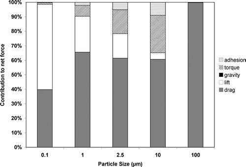
Whether a particle resuspends or not depends on the balance between the aerodynamic and adhesion forces. Our analysis indicates that, above the threshold friction velocity, u* t , translational drag is the dominant force under most circumstances. For particles in the 1–20 μ m range, the torque is a major component, and may very well be responsible for overcoming the adhesive forces. Contrary to early resuspension studies, but in accord with recent results, the aerodynamic lift is significant and cannot be neglected for particles smaller than ∼ 10 μ m. When torque is large, the Magnus force can increase lift by a factor of three for 10 μ m particles and a factor of 200 for 1 μ m particles. The adhesion force increases with particle size as expected with the deformation making a significant contribution above ∼ 100 μ m. The deformation is responsible for about 3%, 10%, and 35% of the total adhesion for 100, 200, and 500 μ m particles, respectively. In all cases, gravity is negligible. An example of a force analysis is shown in for five particle sizes.
Threshold Friction Velocity
The model is used to calculate a threshold friction velocity from a theoretical standpoint. The relative magnitude of forces changes significantly with particle diameter (e.g., ), and this leads to the peculiar shape depicted in . A wind speed that is three standard deviations above the mean is used to calculate aerodynamic forces. A value of three standard deviations was chosen to capture 99.87% of the wind speeds that will be observed for a given mean. For large diameters, particles about 400 μ m in diameter are the most susceptible to resuspension, which qualitatively matches the traditional, empirical results outlined by CitationIversen and White (1982) who observed a minima at about 100 μ m.
FIG. 4 The threshold friction velocity for particle resuspension. Note that resuspension can occur well below these threshold friction velocities as a result of random turbulent fluctuations.
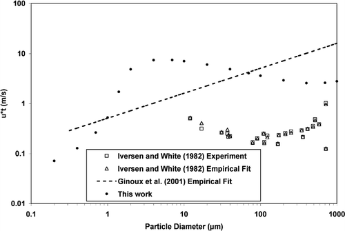
At smaller particle sizes, the threshold friction velocity deviates significantly from what might be extrapolated from the large diameter results. This may mean that small particles can be resuspended at much lower friction velocities than was previously thought. However, our trend line for particles < 4 μ m in diameter shows a steep decrease as particle diameter decreases. This may be compared with the decrease, admittedly less steep, in the empirical fit of CitationGinoux et al. (2001) who extrapolated a linear relationship between particle diameter and threshold friction velocity. The variation in threshold friction velocity with diameter most likely occurs because as diameter increases the surface area available for wind to act upon also increases. But an increase in diameter also increases the mass of the particle so competing processes are at work.
Resuspension occurs at values well below the threshold friction velocity. This is because random velocity fluctuations are occasionally strong enough to launch a particle. This was corroborated by the experiments and simulations of CitationBraaten et al. (1990). In a wind tunnel experiment on assorted particle types and sizes, the upper 20% of the distribution of turbulent fluctuations was responsible for approximately 65% of the particle resuspension (CitationWu et al. 1992).
The Expected Path of a Particle
The path of a particle very near the surface is described in the following discussion. We present results for a broad range of particle sizes and flow fields, and illustrate in quantitative terms the motion of a particle launched from the surface as a result of aerodynamic processes. Example trajectories show a close resemblance to earlier work of CitationAnderson (1987).
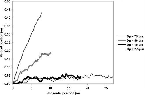
How a particle is affected by turbulent fluctuations depends both on the particle diameter and the mean wind speed. suggests that heavier particles are less susceptible to turbulent fluctuations than lighter particles. For friction velocities of 0.5, 0.8, and 1.0 m/s the approximate threshold diameters are 80, 60, and 50 μ m, respectively. Particles smaller than this threshold will match the wind speed almost exactly while particles larger than this threshold will move in much smoother trajectories than a Lagrangian wind parcel at the same location.
This diameter and wind speed dependence matches the experimental results of CitationWu et al. (1992), who found that particles with a relaxation time smaller than the turbulent time scale are dominated by the effects of turbulence and particles move with the air flow. CitationHunt and Nalpanis (1985) and CitationAnderson (1987) similarly observed that heavy particles “cut through” turbulent fluctuations and exhibit less violent motions than small particles.
The instantaneous velocity of a 75 μ m particle and a 1 μ m particle are shown in and , respectively. The 1 μ m particle consistently matches the wind speed in both the vertical and horizontal directions while the 75 μ m particle frequently lags the wind speed by a significant amount.
FIG. 7 The instantaneous horizontal, u, and vertical, w, wind velocities and the horizontal, u|*bsub*|p|*esub*|, and vertical, w|*bsub*|p|*esub*|, velocities for a 75 μ m particle at u* = 0.8 m/s.
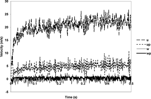
FIG. 8 The instantaneous horizontal, u, and vertical, w, wind velocities and the horizontal, u|*bsub*|p|*esub*|, and vertical, w|*bsub*|p|*esub*|, velocities for a 1 μ m particle at u* = 0.5 m/s.
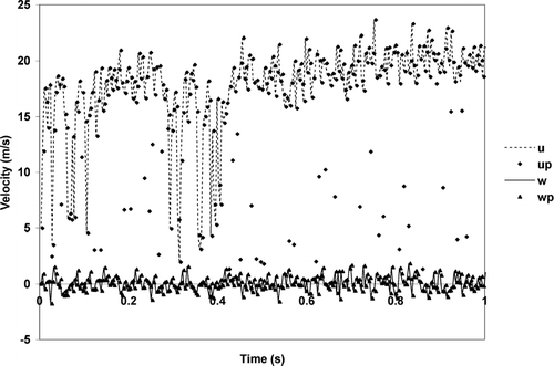
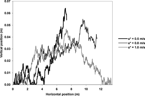
Graphs of particle position shown in and exhibit a quasi-periodicity. The length of time between peaks ranges from 0.006 to 0.26 seconds. These intermittent leaps are the same order of magnitude but do not exactly match the intermittency described by CitationJiménez and Moin (1991). However, as with the Jiménez and Moin result, the period becomes longer with increasing particle size and becomes shorter with increasing friction velocity. It should be noted that these fluctuations are also occurring at heights sufficiently above the sublayer indicating that turbulent bursting is probably not the causal mechanism.
The Impact of Particle Diameter
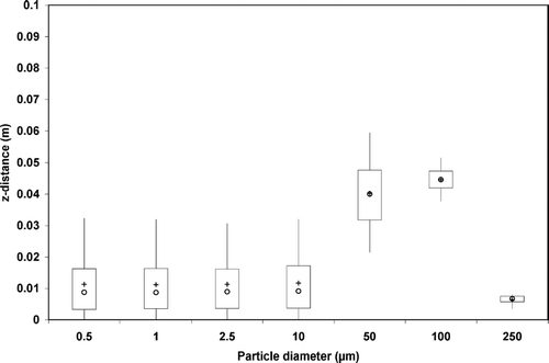
Particle diameter plays a major role in determining how far a particle will travel during a given episode. The average distances traveled in the first 0.176 seconds are shown in , , , for the horizontal and vertical distances, respectively. These results were taken from 1500 simulations. The error bars represent one standard deviation about the mean. In the horizontal direction smaller particles reach significantly farther distances in the x direction. In the vertical direction, particles in the tens of microns achieve approximately the same height, with 50 and 100 μ m particles showing some increased distance. Particles larger than ∼ 300 μ m are not typically resuspended at the friction velocities shown.
FIG. 9 The horizontal distance traveled by particles of various diameters over 0.176 seconds at u* = 0.75 m/s. The ends of the box denote the first and third quartiles of the model results. Lines extend to the 5th and 95th percentiles. The median value is shown with a circle. The mean is shown by a cross.
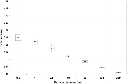
FIG. 10 The horizontal distance traveled by particles of various diameters over 0.176 seconds at u* = 0.50 m/s. The ends of the box denote the first and third quartiles of the model results. Lines extend to the 5th and 95th percentiles. The median value is shown with a circle. The mean is shown by a cross.
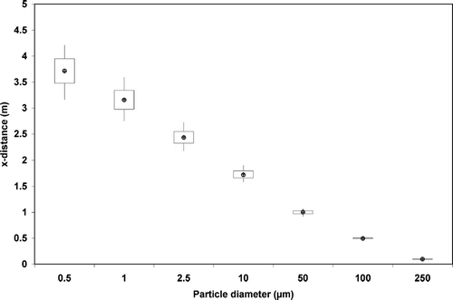
FIG. 11 The vertical distance traveled by particles of various diameters over 0.176 seconds at u* = 0.75 m/s. The ends of the box denote the first and third quartiles of the model results. Lines extend to the 5th and 95th percentiles. The median value is shown with a circle. The mean is shown by a cross.
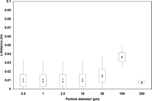
FIG. 12 The vertical distance traveled by particles of various diameters over 0.176 seconds at u* = 0.50 m/s. The ends of the box denote the first and third quartiles of the model results. Lines extend to the 5th and 95th percentiles. The median value is shown with a circle. The mean is shown by a cross.
The Impact of Windspeed
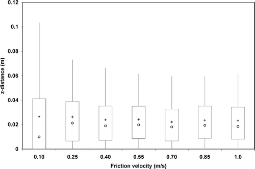
There is a marked difference in how particles respond in different wind fields. To analyze this, we have compared the results for a range of friction velocities typically observed in the field. Larger wind speeds cause particles to travel farther, and larger friction velocities lead to larger turbulent fluctuations. The results shown in , , , illustrate the mean difference in trajectories for a number of different friction velocities. A total of 1500 simulations were run in each case. Each simulation covers 0.65 seconds with the particle beginning at rest. The difference in position over this time is shown on the y-axis. In the x-direction, the distance traveled by a particle increases monotonically with wind speed with a steeper increase for the 1 μ m particle than for the 10 μ m particle. The distance traveled in the vertical direction is relatively consistent over a range of wind speeds.
FIG. 13 The horizontal distance traveled by a 1 μ m particle over 0.65 seconds at various friction velocities. The ends of the box denote the first and third quartiles of the model results. Lines extend to the 5th and 95th percentiles. The median value is shown with a circle. The mean is shown by a cross.
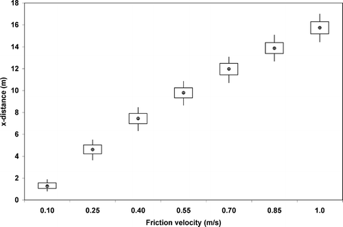
FIG. 14 The horizontal distance traveled by a 10 μ m particle over 0.65 seconds at various friction velocities. The ends of the box denote the first and third quartiles of the model results. Lines extend to the 5th and 95th percentiles. The median value is shown with a circle. The mean is shown by a cross.
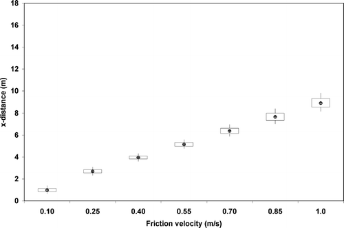
FIG. 15 The vertical distance traveled by a 1 μ m particle over 0.65 seconds at various friction velocities. The ends of the box denote the first and third quartiles of the model results. Lines extend to the 5th and 95th percentiles. The median value is shown with a circle. The mean is shown by a cross.
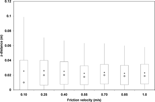
FIG. 16 The vertical distance traveled by a 10 μ m particle over 0.65 seconds at various friction velocities. The ends of the box denote the first and third quartiles of the model results. Lines extend to the 5th and 95th percentiles. The median value is shown with a circle. The mean is shown by a cross.
CONCLUSIONS
We have built a model describing the motion of a spherical particle entrained in turbulent flow. Our analysis includes the near-surface region accounting for coherent structures in the quasi-laminar sublayer and the adhesive forces that resist particle motion. Turbulent fluctuations are reproduced in the boundary layer, and the response of surface particles at moderate Reynolds numbers is illustrated.
A particle becomes entrained in turbulent flow when the magnitude of fluid forces exceeds that of adhesion forces. The aerodynamic drag, lift, and torque are all important factors in the resuspension process for small particles. For large particles (D p > 1 μ m), the drag force dominates. However the lift force cannot be neglected as is sometimes asserted, and quantifying near-surface lift by assuming the creeping flow solution may significantly skew results at moderate Reynolds number.
When the critical force required to remove a particle is known, it is possible to calculate a threshold friction velocity. We have quantified the threshold friction velocity based on first principles and a theoretically-derived force balance. The threshold friction velocity does not exhibit the traditional D p dependence but rather appears to be the union of the two existing theories. At the upper limit of particle sizes, a local minimum indicates that, in terms of susceptibility to resuspension, an optimum particle diameter for resuspension exists. This analysis places the local minimum around D p = 400 μ m. At the lower limit of particle sizes the threshold friction velocity declines linearly with diameter corresponding to the empirical results of CitationGinoux et al. (2001). In both cases the threshold friction velocity should be used with care as resuspension can be initiated by instantaneous turbulent velocity fluctuations even when the mean wind flow is considerably less than the threshold velocity.
Particle trajectories are most sensitive to changes in the wind speed and the particle diameter. In general, larger diameter particles will travel shorter distances in a given time. Increasing the wind speed increases the distance a particle travels in the same amount of time. Small particles are highly susceptible to turbulent fluctuations and follow the Lagrangian wind trajectory almost exactly. Larger particles follow smoother trajectories and are less prone to instantaneous changes in wind speed. Particles that are subject to turbulent fluctuations exhibit a quasi-periodicity. The exact mechanism behind this process is not clear although it resembles intermittency observed by other investigators.
Acknowledgments
The authors acknowledge the coding suggestions of Dr. Benoit Morel, the helpful turbulence discussions with Drs. Peter Adams, Nadine Aubry, and Mitchell Small, and discussions with others in the Center for Atmospheric Particle Studies. This work was funded by National Science Foundation Grant BES-9714162 and a National Science Foundation Graduate Student Fellowship.
REFERENCES
- Anderson , R. S. 1987 . Eolian Sediment Transport as a Stochastic Process: The Effects of a Fluctuating Wind on Particle Trajectories . Journal of Geology , 95 : 497 – 512 .
- Arya , S. P. 1999 . Air Pollution Meteorology and Dispersion , New York : Oxford University Press .
- Asmolov , E. S. 1999 . The Inertial Lift on a Spherical Particle in a Plane Poiseuille Flow At Large Channel Reynolds Number . J. Fluid Mech. , 381 : 63 – 87 .
- Bagchi , P. and Balachander , S. 2002 . Shear Versus Vortex-Induced Lift Force on a Rigid Sphere at Moderate Re . J. Fluid Mech. , 473 : 379 – 388 .
- Bagnold , R. A. 1941 . The Physics of Blown Sand and Desert Dunes , London : Chapman and Hall .
- Bowling , R. A. 1988 . A Theoretical Review of Particle Adhesion , 129 – 142 . New York : Plenum Press .
- Braaten , D. A. , Paw , U. K. T. and Shaw , R. H. 1990 . Particle Resuspension in a Turbulent Boundary Layer—Observed and Modeled . J. Aerosol Sci. , 21 : 613 – 628 .
- Brodkey , R. S. , Wallace , J. E. and Eckelmann , H. 1974 . Some Properties of Truncated Turbulence Signals in Bounded Shear Flows . J. Fluid Mech. , 63 : 209 – 224 .
- Chepil , W. S. 1945a . Dynamics of Wind Erosion: I Nature of Movement of Soil By Wind . Soil Science , 60 : 305 – 320 .
- Chepil , W. S. 1945b . Dynamics of Wind Erosion: II . Soil Science , 60 : 397 – 411 .
- Chepil , W. S. 1958 . The Use of Evenly Spaced Hemispheres to Evaluate Aerodynamic Forces on a Soil Surface . Transactions, American Geophysical Union , 39 : 397 – 404 .
- Cleaver , J. W. and Yates , B. 1973 . Mechanism of Detachment of Colloidal Particles from a Flat Substrate in a Turbulent Flow . Journal of Colloid and Interface Science , 44 : 464 – 474 .
- Clift , R. , Grace , J. R. and Weber , M. E. 1978 . Bubbles, Drops, and Particles , 380 New York : Academic Press, Inc. .
- Cornelis , W. M. , Gabriels , D. and Hartmann , R. 2004 . A Parameterisation for the Threshold Shear Velocity to Initiate Deflation of Dry and Wet Sediment . Geomorphology , 59 : 43 – 51 .
- Dandy , D. S. and Dwyer , H. A. 1990 . A Sphere in Shear Flow at Finite Reynolds Number: Effect of Shear on Particle Lift, Drag, and Heat Transfer . J. Fluid Mech. , 216 : 381 – 410 .
- Davis , R. H. , Zhao , Y. , Galvin , K. P. and Wilson , H. J. 2003 . Solid-Solid Contacts Due to Surface Roughness and Their Effects on Suspension Behaviour . Phil. Trans. R. Soc. Lond. A , 361 : 871 – 894 .
- Dennis , S. C. R. , Singh , S. N. and Ingham , D. B. 1980 . The Steady Flow Due to a Rotating Sphere at Low and Moderate Reynolds Numbers . J. Fluid Mech. , 101 : 257 – 279 .
- Eichorn , R. and Small , S. 1964 . Experiments on the Lift and Drag of Spheres Suspended in Poiseuille Flow . J. Fluid Mech. , 20 : 513 – 527 .
- Fécan , F. , Marticorena , B. and Bergametti , G. 1999 . Parameterization of the Increase in the Aeolian Erosion Threshold Wind Friction Velocity Due to Soil Moisture for Arid and Semi-Arid Areas . Ann. Geophysicae , 17 : 149 – 157 .
- Ferrero , E. , Anfossi , D. , Tinarelli , G. and Tamiazzo , M. 2000 . Intercomparison of Lagrangian Stochastic Models Based on Two Different Pdfs . Int. J. Environment and Pollution , 14 : 225 – 234 .
- Fischer , P. F. , Leaf , G. K. and Restrepo , J. M. 2005 . Influence of Wall Proximity on the Lift and Drag of a Particle in an Oscillatory Flow . Journal of Fluids Engineering , 127 : 583 – 594 .
- Flesch , T. K. and Wilson , J. D. 1992 . A Two-Dimensional Trajectory-Simulation Model for Non-Gaussian, Inhomogeneous Turbulence within Plant Canopies . Boundary-Layer Meteorology , 61 : 349 – 374 .
- Frenkiel , F. N. and Klebanoff , P. S. 1973 . Probability Distributions and Correlations in a Turbulent Boundary Layer . The Physics of Fluids , 16 : 725 – 737 .
- Garland , J. A. 1982 . Some Recent Studies of the Resuspension of Deposited Material From Soil and Grass , 1087 – 1097 . Santa Monica, CA : Precipitation Scavenging, Dry Deposition, and Resuspension, Elsevier Science Publishing Co. .
- Ginoux , P. , Chin , M. , Tegen , I. , Prospero , J. M. , Holben , B. , Dubovik , O. and Lin , S.-J. 2001 . Sources and Distributions of Dust Aerosols Simulated with the Gocart Model . Journal of Geophysical Research , 106 : 20255 – 20273 .
- Goren , S. L. 1970 . The Normal Force Exerted by Creeping Flow on a Small Sphere Touching a Plane . J. Fluid Mech. , 41 : 619 – 625 .
- Greeley , R. and Iversen , J. D. 1985 . Physics of Particle Motion , New York : Cambridge University Press .
- Hall , D. 1988 . Measurements of the Mean Force on a Particle Near a Boundary in Turbulent Flow . J. Fluid Mech. , 187 : 451 – 466 .
- Harper , E. Y. and Chang , I. D. 1968 . Maximum Dissipation Resulting from Lift in a Slow Viscous Shear Flow . J. Fluid Mech. , 33 : 209 – 225 .
- Harris , A. R. and Davidson , C. I. 2005 . The Role of Resuspended Soil in Lead Flows in the California South Coast Air Basin . Environ. Sci. Technol. , 39 : 7410 – 7415 .
- Hillel , D. 1998 . Environmental Soil Physics , 771 San Diego : Academic Press .
- Ho , B. P. and Leal , L. G. 1974 . Inertial Migration of Rigid Spheres in Two-Dimensional Unidirectional Flow . J. Fluid Mech. , 65 : 365 – 400 .
- Hunt , J. C. R. and Nalpanis , P. Saltating and Suspended Particles Over Flat and Sloping Surfaces I. Modeling Concepts . Proceedings of the International Workshop on the Physics of Blown Sand . Aarhus, Denmark. pp. 9 – 36 .
- Iversen , J. D. and White , B. R. 1982 . Saltation Threshold on Earth, Mars and Venus . Sedimentology , 29 : 111 – 119 .
- Jalota , S. K. , Prihar , S. S. and Gill , K. S. 1988 . Modified Square Root of Time Relation to Predict Evaporation Trends from Bare Soil . Australian Journal of Soil Research , 26 : 281 – 288 .
- Jiménez , J. , Kawahara , G. , Simens , M. P. , Nagata , M. and Shiba , M. 2005 . Characterization of Near-Wall Turbulence in Terms of Equilibrium and “Bursting” Solutions . Phys. Fluids , 17 : 015105
- Jiménez , J. and Moin , P. 1991 . The Minimal Flow Unit in Near-Wall Turbulence . J. Fluid Mech. , 225 : 213 – 240 .
- Johnson , K. L. , Kendall , K. and Roberts , A. D. 1971 . Surface Energy and the Contact of Elastic Solids . Proceedings of the Royal Society of London. Series A, Mathematical and Physical Sciences , 324 : 301 – 313 .
- Kaftori , D. , Hestroni , G. and Banerjee , S. 1995 . Particle Behavior in the Turbulent Boundary Layer. I. Motion, Deposition, and Entrainment . Phys. Fluids , 7 : 1095 – 1106 .
- Keirsbulck , L. , Labraga , L. , Mazouz , A. and Tournier , C. 2002 . Surface Roughness Effects on Turbulent Boundary Layer Structures . Journal of Fluids Engineering , 124 : 127 – 135 .
- Kjelgaard , J. F. , Chandler , D. G. and Saxton , K. E. 2004 . Evidence for Direct Suspension of Loessial Soils on the Columbia Plateau . Earth Surfaces Processes and Landforms , 29 : 221 – 236 .
- Kurose , R. and Komori , S. 1999 . Drag and Lift Forces on a Rotating Sphere in a Linear Shear Flow . J. Fluid Mech. , 384 : 183 – 206 .
- Laidlaw , M. A. S. , Mielke , H. W. , Filippelli , G. M. , Johnson , D. L. and Gonzales , C. R. 2005 . Seasonality and Children's Blood Lead Levels: Developing a Predictive Model Using Climatic Variables and Blood Lead Data from Indianapolis, Indiana, Syracuse, New York, and New Orleans, Louisiana (USA) . Environmental Health Perspectives , 113 : 793 – 800 .
- Lankey , R. L. , Davidson , C. I. and McMichael , F. C. 1998 . Mass Balance for Lead in the California South Coast Air Basin: An Update . Environmental Research, Section A , 78 : 86 – 93 .
- Leighton , D. and Acrivos , A. 1985 . The Lift on a Small Sphere Touching a Plane in the Presence of a Simple Shear Flow . Journal of Applied Mathematics and Physics , 36 : 174 – 178 .
- Lu , N. and Likos , W. J. 2006 . Suction Stress Characteristic Curve for Unsaturated Soil . Journal of Geotechnical and Geoenvironmental Engineering , 132 : 131 – 142 .
- McKenna Neuman , C. 2003 . Effects of Temperature and Humidity Upon the Entrainment of Sedimentary Particles By Wind . Boundary-Layer Meteorology , 108 : 61 – 89 .
- McKenna Neuman , C. and Nickling , W. G. 1989 . A Theoretical and Wind Tunnel Investigation of the Effect of Capillary Water on the Entrainment of Sediment by Wind . Can. J. Soil Sci. , 69 : 79 – 96 .
- Mclaughlin , J. B. 1993 . The Lift on a Small Sphere in Wall-Bounded Linear Shear Flows . J. Fluid Mech. , 246 : 249 – 265 .
- Miyazaki , T. 2006 . Water Flow in Soils , 418 New York : Taylor and Francis .
- Mollinger , A. M. and Nieuwstadt , F. T. M. 1996 . Measurement of the Lift Force on a Particle Fixed to the Wall in the Viscous Sublayer of a Fully Developed Turbulent Boundary Layer . J. Fluid Mech. , 316 : 285 – 306 .
- Nakagawa , H. and Nezu , I. 1977 . Prediction of the Contributions to the Reynolds Stress from Bursting Events in Open-Channel Flows . J. Fluid Mech. , 80 : 99 – 128 .
- Nezu , I. 2005 . Open-Channel Flow Turbulence and Its Research Prospect in the 21st Century . Journal of Hydraulic Engineering , April : 229 – 246 .
- Niazmand , H. and Renksizbulut , M. 2003 . Surface Effects on Transient Three-Dimensional Flows Around Rotating Spheres at Moderate Reynolds Numbers . Computers & Fluids , 32 : 1405 – 1433 .
- Nicholson , K. W. 1988 . A Review of Particle Resuspension . Atmospheric Environment , 22 : 2639 – 2651 .
- Nikora , V. , Goring , D. , Mcewan , I. and Griffiths , G. 2001 . Spatially Averaged Open-Channel Flow Over Rough Bed . Journal of Hydraulic Engineering , 127 : 123 – 133 .
- Niño , Y. and García , M. 1998 . Using Lagrangian Particle Saltation Observations for Bedload Sediment Transport Modelling . Hydrological Processes , 12 : 1197 – 1218 .
- O'Neill , M. E. 1968 . A Sphere in Contact with a Plane Wall in a Slow Linear Shear Flow . Chemical Engineering Science , 23 : 1293 – 1298 .
- Paw , U. K. T. 1983 . The Rebound of Particles from Natural Surfaces . Journal of Colloid and Interface Science , 93 : 442 – 452 .
- Pedinotti , S. , Mariotti , G. and Banerjee , S. 1992 . Direct Numerical Simulation of Particle Behaviour in the Wall Region of Turbulent Flows in Horizontal Channels . Int. J. Multiphase Flow , 18 : 927 – 941 .
- Pope , S. B. 2000 . Turbulent Flows , New York : Cambridge University Press .
- Ranade , M. B. 1987 . Adhesion and Removal of Fine Particles on Surfaces . Aerosol Science and Technology , 7 : 161 – 176 .
- Rashidi , M. , Hetsroni , G. and Banerjee , S. 1990 . Particle-Turbulence Interaction in a Boundary Layer . Int. J. Multiphase Flow , 16 : 935 – 949 .
- Sabersky , R. H. , Acosta , A. J. , Hauptmann , E. G. and Gates , E. M. 1999 . Fluid Flow , Upper Saddle River, NJ : Prentice Hall .
- Saffman , P. G. 1965 . The Lift on a Small Sphere in a Slow Shear Flow . J. Fluid Mech. , 22 : 385 – 400 .
- Sehmel , G. A. 1980 . Particle Resuspension: A Review . Environment International , 4 : 107 – 127 .
- Seinfeld , J. H. and Pandis , S. N. 1998 . Atmospheric Chemistry and Physics , 916 – 957 . New York : John Wiley & Sons, Inc. .
- Soltani , M. and Ahmadi , G. 1994 . On Particle Adhesion and Removal Mechanisms in Turbulent Flow . J. Adhesion Sci. Technol. , 8 : 763 – 785 .
- Soltani , M. and Ahmadi , G. 1995a . Direct Numerical Simulation of Particle Entrainment in Turbulent Channel Flow . Phys. Fluids , 7 : 647 – 657 .
- Soltani , M. and Ahmadi , G. 1995b . Particle Detachment From Rough Surfaces in Turbulent Flows . J. Adhesion , 51 : 105 – 123 .
- Temple , G. F. J. 1958 . An Introduction To Fluid Dynamics , Oxford : Clarendon Press .
- Tennekes , H. and Lumley , J. L. 1972 . A First Course in Turbulence , Cambridge : The MIT Press .
- Tsai , C. -J. , Pui , D. Y. H. and Liu , B. Y. H. 1991 . Elastic Flattening and Particle Adhesion . Aerosol Science and Technology , 15 : 239 – 255 .
- Tsuji , Y. , Morikawa , Y. and Mizuno , O. 1985 . Experimental Measurement of the Magnus Force on a Rotating Sphere At Low Reynolds Numbers . Trans. ASME , 197 : 484 – 488 .
- Vainshtein , P. , Ziskind , G. , Fichman , M. and Gutfinger , C. 1997 . Kinetic Model of Particle Resuspension by Drag Force . Physical Review Letters , 78 : 551 – 554 .
- Ventura , F. , Snyder , R. L. and Bali , K. M. 2006 . Estimating Evaporation from Bare Soil Using Soil Moisture Data . Journal of Irrigation and Drainage Engineering , 132 : 153 – 158 .
- Wang , H.-W. 1990 . Effects of Inceptive Motion on Particle Detachment from Surfaces . Aerosol Science and Technology , 13 : 386 – 393 .
- Wen , H. Y. and Kasper , G. 1989 . On the Kinetics of Particle Reentrainment from Surfaces . J. Aerosol Sci. , 20 : 483 – 498 .
- Williams , J. J. 1986 . Aeolian Entrainment Thresholds in a Developing Boundary Layer , PhD Thesis London : Department of Geography and Earth Science, University of London .
- Wu , F.-C. and Jiang , M.-R. 2007 . Numerical Investigation of the Role of Turbulent Bursting in Sediment Entrainment . Journal of Hydraulic Engineering , 133 : 329 – 334 .
- Wu , F.-C. and Yang , K.-H. 2004 . Entrainment Probabilities of Mixed-Size Sediment Incorporating Near-Bed Coherent Structures . Journal of Hydraulic Engineering , 130 : 1187 – 1197 .
- Wu , Y.-L. , Davidson , C. I. and Russell , A. G. 1992 . Controlled Wind Tunnel Experiments for Particle Bounceoff and Resuspension . Aerosol Science and Technology , 17 : 245 – 262 .
- Yanful , E. K. and Choo , L.-P. 1997 . Measurement of Evaporative Fluxes from Candidate Cover Soils . Can. Geotech. J. , 34 : 447 – 459 .
- Young , T. M. , Heeraman , G. A. , Sirin , G. and Ashbaugh , L. L. 2002 . Resuspension of Soil as a Source of Airborne Lead Near Industrial Facilities and Highways . Environ. Sci. Technol. , 36 : 2484 – 2490 .
- Yung , B. P. K. , Merry , H. and Bott , T. R. 1989 . The Role of Turbulent Bursts in Particle Re-Entrainment in Aqueous Systems . Chemical Engineering Science , 44 : 873 – 882 .
- Zeng , L. , Balachander , S. and Fischer , P. 2005 . Wall-Induced Forces on a Rigid Sphere at Finite Reynolds Number . J. Fluid Mech. , 536 : 1 – 25 .
- Zheng , Xiaojing , Huang , Ning and Zhou , You-He . 2003 . Laboratory Measurement of Electrification of Wind-Blown Sands and Simulation of Its Effect on Sand Saltation Movement . J. Geophys. Res. , 108 D10 433, Doi: 10.1029/2002JD002572
- Zheng , Xiaojing , Xie , Li and Zou , Xue-Yong . 2006 . Theoretical Prediction of Liftoff Angular Velocity Distributions of Sand Particles in Windblown Sand Flux . J. Geophys. Res. , 111 D11109, Doi: 10.1029/2005JD006164
- Zhou , J.-F. , Zhang , Q. and Li , J.-C. 2005 . Probability Distribution of Near-Wall Turbulent Velocity Fluctuations . Applied Mathematics and Mechanics , 26 : 1245 – 1254 .
- Ziskind , G. , Fichman , M. and Gutfinger , C. 1995 . Resuspension of Particulates from Surfaces to Turbulent Flows—Review and Analysis . J. Aerosol Sci. , 26 : 613 – 644 .
