Abstract
We investigate the filtration performance of composite filters composed of micrometer and nanometer fibers. The filter quality is evaluated using the figure of merit, also known as the quality factor. We use analytical expressions for the pressure drop and filtration efficiency to compute the figure of merit. The effects on the figure of merit by fiber diameter, solidity, and thickness of nanometer and micrometer fibers and face velocity are investigated. Experimental data obtained using conventional filter media and nanofiber composite filters are then used to verify the calculated results. We find that for large particles (approximately 0.1 μm and above), nanofibers can improve the figure of merit compared to conventional filters. Smaller fiber size, larger solidity, and thickness of the nanofiber layer lead to better filtration performance in this size range. For small particles (approximately below 0.1 μm), nanofibers do not improve the figure of merit compared to conventional filter media. Larger fiber size, smaller solidity, and thickness of the nanofiber layer are preferred in this size range. We demonstrate that our procedure using analytical expression is a fast and effective tool for filter media design.
1. INTRODUCTION
Figure of merit (FOM, also know as the quality factor, see CitationBrown 1993) is often used to evaluate the filtration performance of filters (CitationHinds 1998; CitationDhaniyala and Liu 1999; CitationWang et al. 2007b). FOM is defined as:
Nanofiber media has emerged as a promising media which can provide a greater filtration efficiency and higher performance than conventional fibers. The dust cake may build up on the surface of nanofiber media and be easily cleaned off, ensuring high filtration efficiency and long filter life. The nonwoven industry generally considers nanofibers as having a diameter of less than 0.5 micron (CitationGeorge 2007). A number of companies are developing filtration media using nanofibers, such as Ultra-Web® and Fibra-Web® nanofiber media technology by Donaldson Company, Finetex MatsTM by Finetex Technology Inc., and AMSOIL Ea Air Filters. CitationSubbiah et al. (2005), CitationGeorge (2007), and CitationEllison et al. (2007) focused on manufacturing techniques for nanofibers. CitationGraham et al. (2002), CitationGradón et al. (2006), CitationKalayci et al. (2006), CitationKim et al. (2006), CitationPodgórski et al. (2006), CitationBarhate and Ramakrishna (2007), and CitationWang et al. (2007b) investigated production and filtration performances of nanofibers.
In the filtration literature, a large number of analytical expressions exist for the filtration efficiency and pressure drop of fibrous filters. We make use of such expressions and take the structure in nanofiber composite filters into account to compute FOM. This approach provides fast and inexpensive estimation of the filter performance. It may be used in nanofiber filter design to optimize filtration performance by changing parameters such as solidity, fiber size, and thickness. We also present experimental results obtained using nanofiber composite filters and conventional filter media to demonstrate the reliability of our approach.
2. ANALYSIS FOR FOM USING ANALYTICAL EXPRESSIONS
Calculation of FOM involves the penetration and pressure drop. Since nanofibers are to be considered, we choose analytical expressions with the slip effects considered. The pressure drop based on the Kuwabara flow with slip effect is (CitationBrown 1993, Equation Equation3.65):
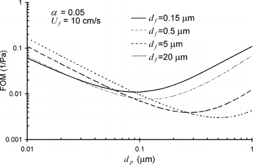
The fiber size, solidity, and face velocity all influence the FOM of a uniform filter. Their effects are well studied for conventional micrometer fibers (e.g., CitationHinds 1998). A limited number of studies (CitationKalayci et al. 2006; CitationPodgórski et al. 2006; CitationWang et al. 2007b) have revealed these effects for nanofibers. We systematically examine the effects of the fiber size, solidity, and face velocity on FOM for nanofibers. shows the effects of the fiber size df on FOM. For large particles (above 0.3 μm), the FOM increases as the fiber size decreases; for very small particles (below 0.02 μm), the FOM decreases as the fiber size decreases. Compared to micrometer fibers, the nanofibers (0.15 μm and 0.5 μm) give better filtration performance for particles larger than about 0.1 μm, but worse performance for particles less than about 0.1 μm. The reason is when df decreases, the pressure drop increases at a much faster rate than single fiber efficiency due to diffusion. Therefore FOM decreases with decreased df for small particles. For larger particles, the combined single fiber efficiency due to interception and inertial impaction can increase faster than pressure drop. Therefore FOM increases with decreased df for large particles. CitationPodgórski et al. (2006) obtained results similar to ours shown in .
FIG. 1 Effects of the fiber size df on FOM; the solidity is α=0.05, and the face velocity Uf = 10 cm/s in this calculation.
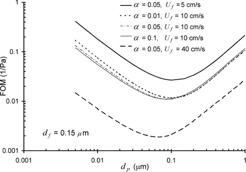
illustrates the effects of the solidity α and the face velocity Uf on FOM. All the curves are for df = 0.15 μm. The three curves in the middle share the same face velocity but different values of solidity. They crossover near dp = 0.1 μm. For particles smaller than about 0.1 μm, lower solidity leads to better FOM; for particles larger than about 0.1 μm, the three curves are close, though a careful examination shows that higher solidity leads to slightly better FOM. Increasing solidity gives rise to higher Δp and higher ER ,ED . For small particles, the increase of Δp outweighs the increase of ED , therefore FOM decreases with increasing α. For large particles, the increase of ER outweighs the increase of Δp, therefore FOM increases with increasing α. CitationKalayci et al. (2006) obtained similar conclusions regarding the effect of solidity on FOM for nanofiber filters. also shows three curves with the same solidity α = 0.05 but different face velocities. FOM increases as the face velocity decreases in the whole particle size range below 1 μm. The reason is that Δp decreases and ED increases as Uf decreases. Although EI decreases as Uf decreases, its effect in the range we are considering is not strong enough to outweigh those of Δp and ED . CitationDhaniyala and Liu (1999) developed the following correlation between FOM and Uf for fiberglass filters
FIG. 2 Effects of the solidity α and the face velocity Uf on FOM. The fiber diameter is df = 0.15 μm.
The correlation shows that FOM increases as Uf decreases, in agreement with our results.
We can see that FOM curves for different fiber sizes crossover in . We focus on the particle size at which the curves for 0.15 μm and 20 μm fibers crossover. The crossover position depends on α and Uf , and is listed in . The crossover position shifts to larger particle sizes when α and Uf decrease. At the left of the crossover position, 20 μm fibers perform better; at the right of the crossover position, 0.15 μm fibers perform better. The results here are helpful for determination whether to use nanofiber or micrometer fibers in an application with specified target particle size and face velocity.
TABLE 1 The particle size at which the FOM curves for 0.15 μm and 20 μm fibers crossover is shown as a function of α and Uf
Next we consider composite filters composed of layers of nanofibers and micrometer fibers. The nanofiber layer is used for its high filtration efficiency and the micrometer fiber layer provides necessary mechanical support. We use Equations (2)–(6) to compute the pressure drop and efficiency for the two layers. The pressure drop of the composite filter is the sum of the pressure drops of the two layers; the penetration of the composite filter is the product of the penetrations of the two layers. The fiber diameter df , solidity α, and thickness t in the two layers can be different. We use subscripts “1” and “2” to distinguish the two layers. The order of the two layers does not matter in our calculation. In practical applications, the nanofiber layer is usually placed at the upstream side of the filter, which leads to dust cake building up on the nanofibers and allows easy cleaning of the dust cake. FOM of the composite filters is influenced by α1, d f1, α2, d f2, t 1, and t 2. We note that FOM of a filter with uniform df and α is independent of the filter thickness, but a simple derivation using the definition of FOM shows that FOM of a composite filter depends on the thickness ratio t 1/t 2. We construct different model composite filters by varying the values of α1, d f1, α2, d f2, and t 1/t 2, as summarized in .
TABLE 2 Model composite filters with different values of α1, d f1, α2, d f2, and t 1/t 2 used in this study. The composite filters are identified by CF1, CF2, …, CF8
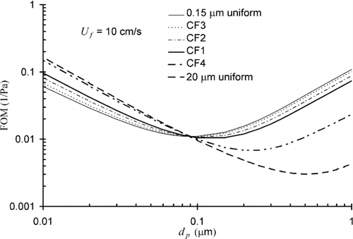
We first look at the effects of the thickness ratio t 1/t 2 by comparing FOM curves of CF1, CF2, and CF3 in . We keep the thickness of the micrometer fiber layer t 1 constant, and change the thickness of the nanofiber layer from 0.15 μm to 1 μm. FOM curves of uniform filters with df = 0.15 μm and 20 μm are also shown in for comparison. Among CF1, CF2, and CF3, the thicker nanofiber layer gives rise to higher FOM for particles larger than about 0.09 μm but lower FOM for particle smaller than about 0.09 μm. Even though the nanofiber layer on CF1 is very thin, FOM for large particles is significantly higher than that for the 20 μm uniform filter and FOM for small particles is higher than that for the 0.15 μm uniform filter. The effects of the solidity in the nanofiber layer α2 are shown in by comparing FOM curves of CF1 and CF4. The value of α2 is 0.05 and 0.01 for CF1 and CF4, respectively. The higher values of α2 leads to higher FOM for particles larger than about 0.09 μm but lower FOM for particle smaller than about 0.09 μm.
FIG. 3 FOM curves for composite filters CF1, CF2, CF3, and CF4 and uniform filters with df = 0.15 and 20 μm. The solidity for the two uniform filters is α = 0.05. The thickness ratio t 1/t 2 is different among CF1, CF2, and CF3; the solidity is different between CF1 and CF4 (see ).
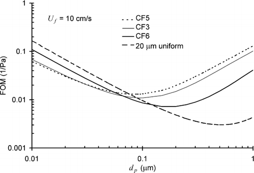
We show the effects of the nanofiber size d f2 in . The micrometer fiber size is 20 μm in CF3, CF5, and CF6, but the values of d f2 is changed from 0.08 μm to 0.5 μm. The smaller nanofibers can improve FOM more for large particles but lead to lower FOM for small particles.
FIG. 4 FOM curves for composite filters CF3, CF5, and CF6 and uniform filters with df = 20 μm. We change d f2 from 0.08 μm to 0.5 μm and keep other parameters constant among CF3, CF5, and CF6 (see ). The solidity for the 20 μm filter is α = 0.05.
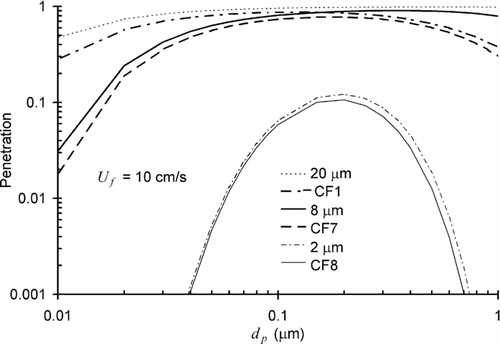
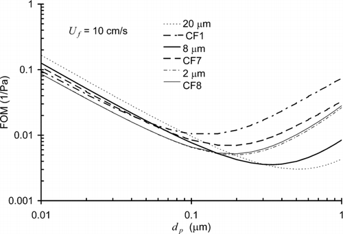
The size of the micrometer fibers d f1 in the composite filter also influences its FOM. We look at three different values of d f1: 20 μm, 8 μm, and 2 μm in CF1, CF7, and CF8, respectively. The nanofiber layer with d f2= 0.15 μm is the same in all three composite filters. We also consider three uniform filters with the fiber size 20 μm, 8 μm, and 2 μm, which are the same as the micrometer fiber layers in CF1, CF7, and CF8. Comparison of the FOM curves of the composite filters and their corresponding uniform filters in shows the effects of adding a nanofiber layer on a micrometer fiber layer. The effect is very limited for 2 μm fiber layer, but significant for 20 μm fiber layer. The reason is that the efficiency of the 2 μm fiber layer is already high; the addition of the nanofiber layer does not change the efficiency by much. The efficiency of the 20 μm fiber layer is low; the addition of the nanofiber layer changes the efficiency substantially. To illustrate this point, we plot the penetration of CF1, CF7, CF8 and their corresponding uniform filters in . For calculation of the penetration, we use t 1= 1 mm and t 2= 0.15 μm in the three composite filters and the thickness is 1 mm in the three uniform filters. It can be seen that the curves of CF8 and 2 μm fiber layer are almost the same, whereas the curve of CF1 is significantly lower than that of 20 μm fiber layer. We notice in that FOM of CF1 is better than that of CF8 in the whole range of particle size under consideration. Our results suggest that in composite filters, larger fiber size in the micrometer fiber layer may lead to better FOM when the nanofiber layer is fixed.
FIG. 5 FOM curves for composite filters CF1, CF7, and CF8, in which the micrometer fiber size is 20 μm, 8 μm, and 2 μm, respectively. The nanofiber layer with d f2=0.15 μm is the same the three composite filters. FOM curves for three uniform filters with the fiber size 20 μm, 8 μm, and 2 μm are also plotted for comparison.
3. EXPERIMENTAL RESULTS FOR FOM
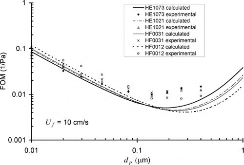
We have performed filtration experiments for standard fiberglass filter media (CitationJapuntich et al. 2007; CitationKim et al. 2007; CitationWang et al. 2007a) and we will present the results in terms of FOM. In we list characteristic parameters for four standard fiberglass filter media manufactured by Hollingsworth and Vose. The HE type filters have smaller fiber size and higher efficiencies than the HF filters. We plot FOM curves for the four filter media in . The experimental results are compared to FOM calculated using the method presented in Section 2. The values of the fiber diameter, solidity, and thickness listed in are used in the calculation. Silver particles in the range of 0.01 to 0.02 μm and NaCl particles in the range of 0.02 to 0.4 μm were used in the experiments. We use the corresponding densities of the particles in the calculation. In the figure, the experimental results show a general agreement with the calculated results in trend. For particles smaller than 0.1 μm, FOM increases with the fiber size; HF0012 has the largest fiber size and highest value of FOM. For particles significantly larger than 0.1 μm, filters with smaller fiber size have higher values of FOM. However, discrepancies are clearly noticed between the experimental and calculated results. This may be resulted from differences in filtration parameters used including the pressure drop and penetration. The calculated pressure drop is larger than the experimental result. For example, the calculated pressure drop for HF0012 is 36.8 Pa at 10 cm/s, compared to 24.0 Pa from experiments. The calculated penetration is 0.848 for 0.4 μm NaCl at 10 cm/s through HF0012, compared to the penetration 0.8 from experiments. Therefore the calculated FOM is smaller than the experimental ones for larger particles in . The reason for these discrepancies could be the non-uniformity of the microstructure in the fiberglass filters. The filters are composed of fibers of different sizes with random orientations (CitationKim et al. 2007; CitationWang et al. 2007a). The non-uniformity could be taken into account in the calculation using empirical correlations. For example, the pressure drop computed using the correlation by CitationDavies (1973) is 27.3 Pa for HF0012 at 10 cm/s, which is close to the experimental value of 24.0 Pa. However, the correlation by CitationDavies (1973) may not be applicable for nanofiber filters. In addition, the effect of non-uniformity on filtration efficiency may be different from the effect on the pressure drop. Therefore, we do not have a universal method to include the non-uniformity in the calculation of FOM.
TABLE 3 Characteristic parameters for four standard fiberglass filter media
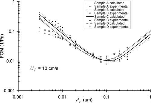
Next we present FOM of composite filters with a single layer of nanofibers and a substrate of micrometer fibers. CitationWang et al. (2007b) reported filtration experimental and numerical simulation results for these composite filters. Here we will show FOM for four different samples, A, B, C, and D with the same micrometer fiber layer. The diameter of the micrometer fibers is about 20 μm from SEM images and the thickness of the micrometer fiber layer is 0.15 mm according to the manufacturer. The diameter of the nanofibers is about 0.15 μm from SEM images. Since there is a single layer of nanofibers, the thickness of the nanofiber layer is taken as 0.15 μm. The effective solidities in the micrometer fiber layer and nanofiber layer are determined by matching the pressure drop calculated using Equation (Equation2) to the experimental data. The matching method gives rise to an effective solidity of α1= 0.09 in the micrometer fiber layer. The effective solidity in the nanofiber layer α2 is determined to be 0.088, 0.069, 0.032, and 0.02 for samples A, B, C, and D, respectively. shows FOM curves of the four samples from experiments and from calculations. Both results show similar curves: smaller solidity gives higher FOM for very small particles; larger solidity gives higher FOM for large particles. Discrepancies between experimental and calculated results may be explained partly by effects of non-uniformity discussed previously.
FIG. 8 FOM curves for composite filters with a single layer of nanofibers and a substrate of micrometer fibers.
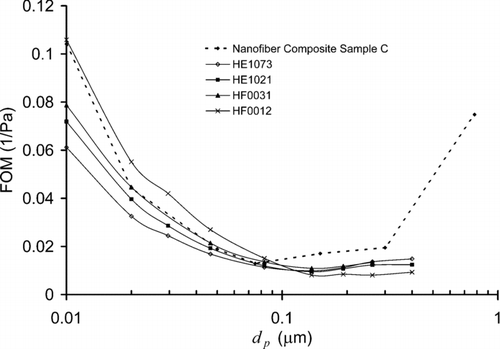
It is of interest to compare FOM of nanofiber composite filters with those of standard filter media. shows the experimental FOM curves of the four standard filter media and nanofiber composite Sample C. The choice is because Sample C has an effective nanofiber solidity close to the solidity of the standard filters. Sample C shows higher values of FOM than the standard filter media for particles larger than about 0.1 μm. For particles smaller than 0.1 μm, FOM of Sample C is between those of HF0031 and HF0012. In general the composite filter has a good FOM in the wide range of particle sizes.
4. CONCLUSIONS
In this work we study the filtration performance evaluated by FOM. Analytical expressions for the pressure drop and single fiber efficiencies are used to calculate FOM. With this approach, we systematically study effects on FOM by the face velocity, solidity, and fiber size down to the nanofiber range. We find that for particles larger than a certain threshold, larger solidity and smaller fiber size lead to higher FOM; for particles smaller than the threshold, smaller solidity and larger fiber size lead to higher FOM. The threshold particle size depends on the face velocity, solidity, and fiber size. In many cases involving nanofiber filters considered here, the threshold size is near 0.1 μm. We calculate the threshold particle size at which the FOM curves of 0.15 μm and 20 μm fibers crossover. The value is in the range of 0.1 ± 0.05 μm and increases when the solidity and face velocity decrease. We calculate FOM for particles smaller than 1 μm and face velocity lower than 40 cm/s. In this range, FOM increases as the face velocity decreases for both nanofiber and micrometer fiber filters.
We calculate FOM of composite filters composed of a layer of nanofibers and a layer of micrometer fibers. If the micrometer fiber layer is the same, larger thickness and solidity and smaller fiber size in the nanofiber layer lead to higher FOM for particles larger than the threshold; smaller thickness and solidity and larger fiber size in the nanofiber layer lead to higher FOM for particles smaller than the threshold. If the nanofiber layer is the same, larger fiber size in the micrometer fiber layer may lead to better FOM.
Our experimental data using standard fiberglass filters and composite nanofiber filters are used to confirm the results from our analysis. The experimental and calculated results agree well with each other qualitatively and show that our analysis works in nanofiber range. Our approach of calculation of FOM provides a fast and simple way to predict the filtration performance of uniform and composite filters. It may be used in nanofiber filter design to optimize filtration performance by changing parameters such as solidity, fiber size, and thickness.
Acknowledgments
The authors are thankful for the support of members of the Center for Filtration Research: 3M Corporation, Cummins Filtration Inc., Donaldson Company, Inc., E. I. du Pont de Nemours and Company, Samsung Semiconductor Inc., Shigematsu Works CO., LTD, TSI Inc., and W. L. Gore & Associates and the affiliate member National Institute for Occupational Safety and Health (NIOSH).
REFERENCES
- Barhate , R. S. and Ramakrishna , S. 2007 . Nanofibrous Filtering Media: Filtration Problems and Solutions from Tiny Materials . J. Membrane Science , 296 : 1 – 8 .
- Brown , R. C. 1993 . Air Filtration , London : Pergamon Press .
- Davies , C. N. , ed. 1973 . Air Filtration , London : Academic Press .
- Dhaniyala , S. and Liu , B. Y. H. 1999 . Investigations of Particle Penetration in Fibrous Filters: Part II. Theoretical . Journal of the IEST , 42 ( 2 ) : 40 – 46 .
- Ellison , C. J. , Phatak , A. , Giles , D. W. , Macosko , C. W. and Bates , F. S. 2007 . Melt Blown Nanofibers: Fiber Diameter Distributions and Onset of Fiber Breakup . Polymer , 48 : 3306 – 3316 .
- George , J. 2007 . “ Nanofiber Manufacturing Processes for Filtration Media (Abstract) ” . Orlando, Florida : American Filtration & Separation Society Annual Conference . March, 2007
- Gradón , L. , Bałazy , A. and Podgórski , A. 2006 . “ Nanofibrous Media-Promising Tools for Filtration of Nanosized Aerosol Particles (Abstract) ” . St. Paul, minnesota : The 7th International Aerosol Conference . September, 2006
- Graham , K. , Ouyang , M. , Raether , T. , Grafe , T. , McDonald , B. and Knauf , P. 2002 . “ Polymeric Nanofibers in Air Filtration Applications (abstract) ” . Galveston, Texas : American Filtration & Separation Society Annual Conference . April, 2002
- Hinds , W. C. 1998 . Aerosol Technology, , 2nd , New York : Wiley-Interscience .
- Japuntich , D. , Franklin , L. , Pui , D. , Kuehn , T. , Kim , S. C. and Viner , A. S. 2007 . A Comparison of Two Nano-Sized Particle Air Filtration Tests in the Diameter Range of 10 to 400 Nanometers . J. Nanoparticle Research , 9 : 93 – 107 .
- Kalayci , V. , Ouyang , M. and Graham , K. 2006 . Polymeric Nanofibres in High Efficiency Filtration Applications . Filtration , 6 ( 4 ) : 286 – 293 .
- Kim , G.-T. , Hwang , Y.-J. , Lee , C.-G. , Cheong , S.-I. , Shin , H.-S. , Chull , A.-Y. and Lee , J.-K. 2006 . “ The Performance of Nylon 6 Nanofilters for Removing Nano-Particles (abstract) ” . St. Paul, Minnesota : The 7th International Aerosol Conference . September, 2006
- Kim , S. C. , Harrington , M. S. and Pui , D. Y. H. 2007 . Experimental Study of Nanoparticles Penetration Through Commercial Filter Media . J. Nanoparticle Research , 9 : 117 – 125 .
- Kirsch , A. A. and Stechkina , I. B. 1978 . “ The Theory of Aerosol Filtration with Fibrous Filters ” . In Fundamentals of Aerosol Science , Edited by: Shaw , D. T. New York : Wiley .
- Landahl , H. D. and Hermann , R. G. 1949 . Sampling of Liquid Aerosols by Wires, Cylinders and Slides, and the Efficiency of Impaction of Droplets . J. Coll. Sci. , 4 : 103 – 136 .
- Pich , J. 1965 . The Filtration Theory of Highly Dispersed Aerosols . Staub Reinhalt. Luft. , 5 : 16 – 23 . (in English)
- Pich , J. 1966 . The Effectiveness of the Barrier Effect in Fibre Filters at Small Knudsen Numbers . Staub Reinhalt. Luft. , 26 : 1 – 4 .
- Podgórski , A. , Balazy , A. and Gradoń , L . 2006 . Application of Nanofibers to Improve the Filtration Efficiency of the Most Penetrating Aerosol Particles in Fibrous Filters . Chemical Engineering Science , 61 : 6804 – 6815 .
- Subbiah , T. , Bhat , G. S. , Tock , R. W. , Parameswaran , S. and Ramkumar , S. S. 2005 . Electrospinning of Nanofibers . J. Applied Polymer Science , 96 ( 2 ) : 557 – 569 .
- Thom , A. 1933 . The Flow Past Circular Cylinders at Low Speeds. . Proc. Roy. Soc. , A141 : 651 – 669 .
- Wang , J. , Chen , D. R. and Pui , D. Y. H. 2007a . Modeling of Filtration Efficiency of Nanoparticles in Standard Filter Media . J. Nanopart. Res. , 9 : 109 – 115 .
- Wang , J. , Kim , S.-C. and Pui , D. Y. H. 2007b . Investigation of the Figure of Merit for Filters with a Single Nanofiber Layer on a Substrate . J. Aerosol Sci. , 39 : 323 – 334 .
