Abstract
A field-deployable instrument has been developed that isolates from an ambient aerosol those particles that have critical supersaturations, Sc, within a narrow, user-specified, range. This Differential Activation Separator (DAS) consists of two continuous flow diffusion chambers housed within a single enclosure. Particles are introduced into the upstream chamber referred to as the CCN remover (CCNR) near the centerline between a warm, water-soaked, plate and a cool, continuously circulated, water bath. Those particles that activate at the resulting peak supersaturation, Sp, grow quickly and fall into the water bath. The remaining aerosol enters the second chamber referred to as the CCN separator (CCNS), which differs from the CCNR primarily in the use of a salt solution in the lower bath. The imposed temperature differential establishes an Sp slightly higher than that maintained in the upstream chamber, while the presence of a salt solution at the lower boundary results in a subsaturated region in roughly the lower half of the chamber. Those particles having (Sp)CCNR < S c < (Sp)CCNS activate in this chamber and begin to fall due to gravitational settling. Before reaching the lower bath, the droplets evaporate in the subsaturated environment and continue to travel towards the chamber exit. The previously activated particles in the lower half of the chamber and the unactivated particles in the upper half are extracted in separate flows that are subsequently dried. Calibration of the DAS was achieved by measuring the size distribution of separated particles when a polydisperse ammonium sulfate aerosol was introduced.
INTRODUCTION
The role of aerosols as the nuclei on which cloud droplets form has been understood for over a century (CitationAitken 1880a, Citation1880b). Increased cloud droplet concentration, positively related to cloud condensation nuclei (CCN) concentration, is believed to increase cloud albedo (CitationTwomey 1977; CitationAckerman et al. 2000), increase cloud lifetime (CitationCharlson et al. 1992), and decrease precipitation efficiency (CitationRosenfeld 1999), resulting in a net cooling effect on a regional scale. The preferential growth of CCN through cloud processing also impacts the particle size-dependent addition of mass to an aerosol population. This may enhance its scattering efficiency, and consequently, its single scattering albedo (CitationHegg et al. 2004). On the other hand, the preferential removal of larger and generally less light absorbing CCN during precipitation events may result in a reduction in single scattering albedo. Despite an appreciation of the consequences of changing CCN concentrations, there remain deficiencies in our ability to predict which subset of an aerosol population will serve as CCN in a given circumstance. To quantify the aforementioned effects of CCN on climate, better formulation of the link between the measurable properties, such as size and composition, of aerosol particles and their activation into cloud droplets under prescribed conditions is needed.
An aerosol particle will activate only if the water vapor supersaturation, S, surrounding the particle exceeds its critical supersaturation, Sc. When this condition is satisfied, water vapor rapidly condenses on the droplet, and typically continues doing so until its surroundings become subsaturated. Thus, knowledge of the maximum in-cloud supersaturation, Smax, coupled with the Sc-dependent particle concentration referred to as a CCN spectrum, should be sufficient to predict the resulting cloud droplet concentration. However, heterogeneity of real clouds precludes the use of a single meaningful Smax, while kinetic constraints on condensational growth may inhibit activation of some subset of the aerosol that fits the conventional definition of CCN as having Sc < Smax (CitationChuang et al. 1997). Prediction of CCN spectra is also challenging as the dependency of Sc on particle chemical composition, size, and even shape must be considered directly or through parameterizations. Most current climate models rely on parameterized empirical functions to retrieve CCN spectra (CitationJones et al. 2001), while global aerosol models may include more sophisticated treatment of activation efficiency (CitationSpracklen et al. 2005). However, beyond the consideration of the computational costs of differing predictive schemes, relating the coarse description of an aerosol afforded by either measurements or models to a CCN spectrum is limited by poorly understood activation efficiencies of the complex mixtures representative of ambient aerosols.
Much of what is known about the cloud nucleating behavior of single-component and mixed aerosols is derived from laboratory studies. Although these studies provide the most readily implemented data needed to relate a modeled size- and chemically resolved aerosol to a resulting CCN spectrum, extrapolation of the results of these studies that often employ compositionally simplistic particles to describe the behavior of multi-component ambient aerosols is challenging. Recent studies indicate that there is considerable variability in the Sc of particles composed of different organic compounds and of mixtures of multiple organics (CitationHenning et al. 2005; CitationVanReken et al. 2005). CitationVanReken et al. (2005) showed that secondary organic particles formed from biogenic precursor gases of similar molecular weight possess different activation efficiencies and that those efficiencies vary with the age of the aerosol. Other studies have shown that trace amounts of soluble inorganic compounds can substantially reduce the Sc of particles composed primarily of slightly soluble organics (CitationBilde and Svenningsson 2004). Beyond the difficulty of quantifying the dependence of Sc on the relative abundance of the range of compounds expected in the ambient aerosol, the chemical specificity provided by models may be insufficient to fully employ the laboratory data.
The validity of predictions of activation efficiency from measurable aerosol properties established through laboratory and theoretical studies can be assessed through CCN closure studies. Such studies are designed to test the degree to which observed CCN concentrations or spectra can be predicted based on concurrent measurements of aerosol physical and chemical properties. Comparing the findings of all the studies of this type is complicated by variability both in the instruments used to measure CCN concentration and in those used to characterize the aerosol. For example, different closure studies have relied on CCN concentrations determined through direct counting of the subset of an aerosol that activates at the peak supersaturation, Sp, in the chamber (CitationVanReken et al. 2003), through measurement of the difference in concentration of a sampled aerosol before and after gravitational removal of all CCN (CitationCantrell et al. 2001), through measurement of the droplet size distribution at equilibrium at 100% RH (CitationLiu et al. 1996), and through a calibration-based relationship between Sc and droplet size in a CCN spectrometer (CitationGasparini et al. 2006). Additionally, different investigators employ varied techniques to relate the aerosol data to CCN concentrations. It would seem that insight into the link between size, composition, and Sc of ambient particles could be gained by altering the assumptions and approximations used in the predictions of CCN concentrations to force agreement with those directly measured. However, this approach is compromised by uncertainties in the measured aerosol size distributions, size-resolved composition, and CCN concentrations. Furthermore, for comparisons at a single S, the influence of an incorrect assignment in Sc is strongly dependent upon the concentration of particles having Sc≈ Sp relative to the concentration of all particles having Sc < Sp. Most of the difficulties identified here would be expected to be manifested in variability in closure success. However, superimposed on this inherent variability, there seems to be a systematic bias noted in some recent closure studies in which the ratio of predicted to measured CCN concentration increases with increased aerosol concentration and with decreased inorganic fraction. For example, using data collected during the Indian Ocean Experiment (INDOEX), CitationCantrell et al. (2001) achieved closure for 8 of 10 cases considered, with the 2 exceptions being during a time when the measured organic fraction of the aerosol was elevated. CitationChuang et al. (2000) reported a concentration-dependent bias both in their data collected during the 2nd Aerosol Characterization Experiment (ACE-2) and in a summary of datasets collected by other research groups.
A more direct and meaningful evaluation of the link between Sc and measurable aerosol properties is possible if a previously activated aerosol is first isolated in a manner that preserves particulate mass and composition. The underlying principle of the approaches that have been employed to isolate CCN from all other particles is inertial separation of large cloud droplets from small haze particles. Instruments designed for these measurements can be categorized based upon whether particle activation occurs at uncontrolled supersaturations in natural clouds or at controlled supersaturations in cloud chambers. Perhaps the most widely used inertial CCN separator is the counterflow virtual impactor (CVI; CitationOgren et al. 1985; CitationNoone et al. 1988). The CVI is designed to separate larger cloud droplets into a sample flow that is not contaminated by smaller unactivated particles. Traditionally, CCN concentrations exiting the CVI are measured with a particle counter, precluding retrieval for additional analysis. Furthermore, although it is desirable to quantify CCN concentration at the local in-cloud supersaturation for certain analyses, the imprecise knowledge of that supersaturation limits the utility of the data for refining cloud-aerosol linkages in models in which supersaturation is prescribed. Use of the CVI in this traditional manner requires operation on board aircraft or at hill or mountain sites that are frequently in cloud, which raises operational costs. Instruments that couple a supersaturator and an inertial separator have traditionally employed virtual impactors rather than CVIs, which results in some contamination by unactivated particles that remain in the minor flow. CitationHarrison and Harrison (1985) connected a high-flux thermal diffusion cloud chamber to a Sierra Instruments dichotomous sampler to collect sufficient sample for chemical analysis. The Sc resolution of that instrument was poor because the sample flow was not confined near the centerline of the cloud chamber as is typical in CCN counters. CitationAlofs et al. (1997) developed a system combining an isothermal haze chamber, a cloud chamber, and multiple virtual impactors that was designed to collect milligram quantities of CCN. In that system, CCN that activate at prescribed S are isolated and collected on filters for off-line chemical analysis. Despite the effort taken to maximize flow rates in the instrument, sample durations as long as a day are required to collect sufficient aerosol mass, during which the ambient aerosol characteristics will likely vary. The instruments described above separate all particles with Sc < Sp. Using data collected with such instruments to link particle chemical and physical properties with activation efficiency is challenging because only an upper bound on Sc is known. Additionally, any compositional analysis of the aerosol that is not size-resolved will be strongly influenced by larger particles that contribute little to the overall CCN concentration but contribute substantially to the overall mass concentration.
The constraints realized in the instruments described above inspired the design of a new device called the Differential Activation Separator (DAS), which is capable of separating from an ambient aerosol the population of particles that activate when exposed to a controlled, narrow, user-specified supersaturation range. This separated aerosol remains suspended, thereby enabling subsequent analysis using a variety of instruments.
INSTRUMENT DESCRIPTION
The DAS is an integrated instrument consisting of two horizontal, parallel plate, continuous flow thermal gradient diffusion chambers arranged in series within a single enclosure, as depicted in . The side view of the chamber is not drawn to scale to more clearly illustrate the arrangement of the internal components. The upstream and downstream sections of the chamber remove low Sc and high Sc particles from an introduced aerosol, respectively. The residual aerosol, which remains suspended and is unaltered, is comprised of a population of particles having roughly equal Sc. The design and function of the two chambers are discussed separately below.
FIG 1 Side profile and top view of the DAS. The side profile is exaggerated vertically to more clearly show the internal configuration. The water baths are represented with the textured pattern.
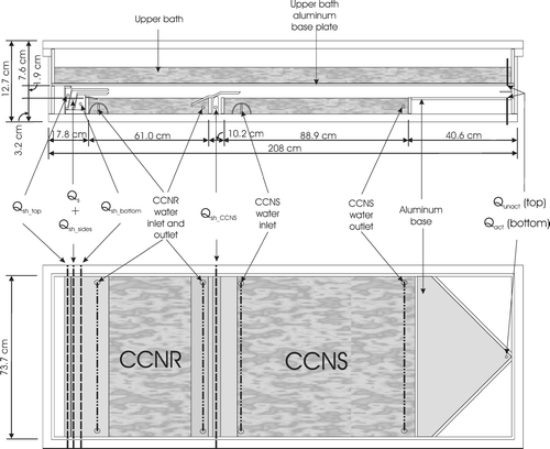
The upstream diffusion chamber, referred to hereafter as the CCN remover (CCNR), is based on the design described in CitationJi et al. (1998). The upper surface within this 1.9 cm high chamber is covered with water-soaked filter paper, while the lower surface is an exposed freshwater bath. Linear temperature and vapor pressure gradients are established in the chamber by maintaining a temperature differential between the wetted surfaces. The bottom bath is always cooler than the filter paper above to prevent convective mixing in the chamber. The result of the temperature and vapor gradients is an S profile such as that shown in , which has a peak, (Sp)CCNR, located approximately at the centerline between the upper and lower surfaces. The flow containing the sample aerosol, Qs, is injected along that centerline, and is sandwiched between two layers of particle-free sheath flow, Qsh_bottom and Qsh_top, as represented by the shaded band in . The sample to sheath flow rate ratio is selected such that the difference between (Sp)CCNR and the S at the top or bottom of the sample flow layer, Δ SCCNR, is about 3% of (Sp)CCNR. Additional particle-free sheath flow, Qsh_sides, is introduced at both edges of the aerosol sample flow to contain it in the central 60% of the width of the chamber, which diminishes any undesirable edge effects. Those particles in the sample flow with Sc ≤ (Sp)CCNR activate and rapidly grow to supermicrometer cloud droplets that gravitationally settle out of the sample layer and into the bath below, as is depicted by the three dashed curves in the CCNR section in . The three lines represent calculated trajectories of particles introduced at the top, center, and bottom of the sample flow. Those trajectories were calculated assuming a mass accommodation coefficient, αc, of 0.05 and a thermal accommodation coefficient, αt, of 1.0 (CitationShaw and Lamb 1999). The solid curves represent trajectories of particles with Sc > (Sp)CCNR that travel through the CCNR and into the downstream chamber, which is referred to as the CCN separator (CCNS).
FIG 2 Simulated velocity (dashed) and supersaturation (solid) profiles for operation with (Sp)CCNR = 0.3%/(Sp)CCNS = 0.35%. The height and thickness of each of the sample layers are reflected in the shaded bands. The blue and red curves / bands represent the CCNR and CCNS, respectively.
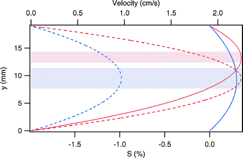
FIG 3 Simulated aerosol trajectories in the CCNR and the CCNS for the three (Sp)CCNR/(Sp)CCNS pairs for which calibration data are provided. The blue and red lines represent particles introduced at the upper and lower boundaries of the sample layer, respectively. Blue shading represents the location of the CCNR and red shading represents the location of the CCNS.
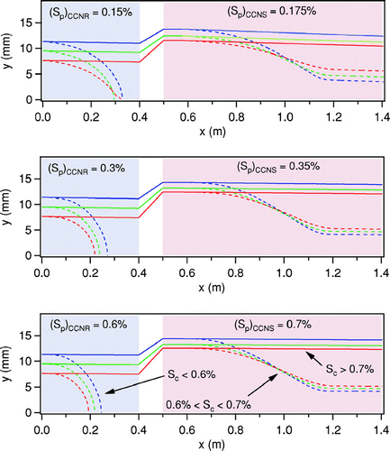
The CCNS is similar in design to the innovative horizontal static thermal diffusion chamber that was first described by CitationSun and Reiss (1984). The developers of that chamber cleverly substituted an acidic solution for the lower water surface to generate a relative humidity profile having a subsaturated layer below a supersaturated layer. By imposing an electric field between the upper and lower plates of the chamber, the effects of multiple growth and evaporation cycles could be studied as charged particles oscillate between the two layers as they repeatedly activate and fall as the force due to gravity exceeds that due to the electric field, then evaporate and rise as the force due to the electric field exceeds that due to gravity. Hogrefe and Keesee (2002) used a similar chamber to study heterogeneous vapor-to-liquid nucleation on glass particles. The CCNS adapts the use of a solution at the lower boundary of the chamber in a continuous flow orientation similar to that of the CCNR. Unlike the instrument designed by CitationSun and Reiss (1984), a salt solution is used in the CCNS and that solution is cooled relative to the upper surface. The result of the temperature differential in the CCNS is a relative humidity profile such as that shown in . As in the CCNR, the sample flow is confined in a thin layer centered at the height of peak supersaturation, which is also depicted in . Upward displacement of the sample layer is accomplished through introduction of additional particle-free sheath flow beneath the total CCNR flow, which is identified as Qsh_CCNS in . Fortuitously, the added flow compresses the sample layer, which offsets the increased S gradient in the CCNS relative to that in the CCNR such that (Δ S/Sp)CCNR∼ (Δ S/Sp)CCNS. To compensate for the increased velocity that results from the added sheath flow, the length of the CCNS is almost twice that of the CCNR. The peak supersaturation in the CCNS, (Sp)CCNS, is slightly higher than that in the CCNR. Thus, particles with (Sp)CCNR ≤ Sc ≤ (Sp)CCNS activate to form cloud droplets and fall due to gravitational settling into the subsaturated layer below, where they evaporate and form a second layer of aerosol, as depicted by the dashed curves in the CCNS section in . Flow rates are maximized for prescribed supersaturations with the constraints that modeled trajectories of particles with Sc < (Sp)CCNR deposit within the first 75% of the length of the CCNR bath and that modeled trajectories of particles with (Sp)CCNR < Sc < (Sp)CCNS reach a stable post-evaporation height within the first 75% of the length of the CCNS bath. It is important to note that, unlike that of some CCN instrument designs, the performance of the DAS is relatively insensitive to droplet mass accommodation coefficient, with the primary impact of a reduction below that assumed for the calculated trajectories being a necessary reduction in flow rates.
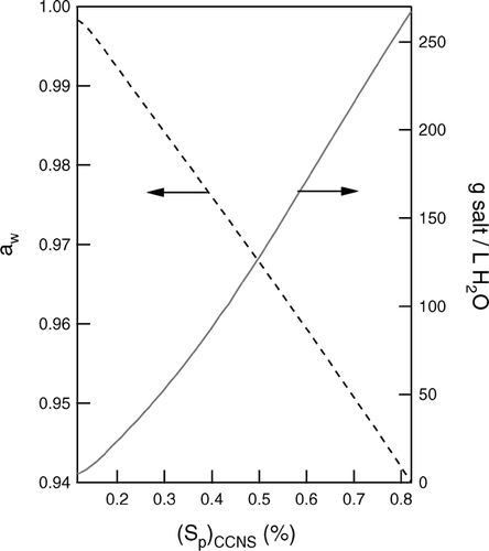
To facilitate extraction of only the activated fraction of the aerosol, the water activity, aw, in the lower bath is selected to produce an RH profile that allows droplets to evaporate into a thin layer located roughly 1/4 of the height of the chamber above the bath surface. The relationship between optimal aw and (Sp)CCNS is shown in . For typical operation, sodium sulfate salt is added to the CCNS bath because it is relatively non-corrosive. Empirical data relating aw to salt concentration reported in CitationTang and Munkelwitz (1994) are used to determine the salt concentration needed to achieve the desired vapor pressure reduction, which is shown on the right axis in . Although a saturated sodium sulfate solution has an aw well below that required for operation at any atmospherically relevant S, a solid decahydrate commonly called Glauber's salt precipitates as aw is reduced below roughly 0.96 at the typical temperatures maintained in the CCNS bath. This limits use of sodium sulfate to (Sp)CCNS ≤ 0.5%. For operation at higher S, sodium chloride is used.
FIG 4 Optimal water activity, aw, in the CCNS bath to cause activated droplets to evaporate in a layer located roughly 1/4 of the height of the chamber above the bath surface (left axis), and the corresponding concentration of sodium sulfate required (right axis).
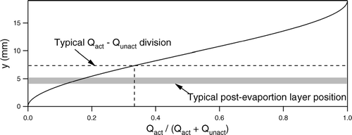
Downstream of the CCNS chamber is an exit region in which vertical acrylic (Plexiglas) walls converge the total flow in the chamber towards the center, after which the unactivated aerosol is extracted from the top of the chamber in the Qunact flow and the activated aerosol is extracted from the bottom in the Qact flow. As the ratio of the flow rate extracted from the top to that extracted from the bottom is increased, the effective thickness of the lower layer containing the activated particles is decreased. The optimal flow rate ratio represents a balance between the increased CCN concentration that results as Qact is decreased and the requirement that the height corresponding to the division between the two layers is above the top of the post-evaporation layer of the activated aerosol. The relationship between the separated layer thickness and the flow rate ratio shown in is non-linear due to the parabolic velocity profile of the laminar flow (Re ≤ 50). The horizontal line in that graph represents the layer thickness for the typically employed flow rate ratio of 2, while the shaded area represents the expected height of the post-evaporation activated aerosol layer.
FIG 5 Division between Qact and Qunact as a function of the ratio of the identified flow rate ratio. The dashed lines represent the typical flow ratio employed and the corresponding division line. The shaded band represents the simulated post-evaporation layer for operation with (Sp)CCNR = 0.3%/(Sp)CCNS = 0.35%.
DAS CONSTRUCTION
Overall Design
The DAS is intended to be operated upstream of an array of analyzers capable of characterizing the physical and chemical properties of the Sc-resolved aerosol, and must therefore be able to provide sufficient sample flow to minimize dilution of what is often an already dilute aerosol. Because sample flow rate through a parallel plate CCN instrument scales approximately with the physical size of the chamber, the DAS was designed to be as large as possible, while still remaining mobile to permit field deployment. The DAS chamber rests on top of a 213 cm (L) × 86 cm (W) × 139 cm (H) aluminum frame onto which all of the external parts needed for operation are secured. It is attached to the frame through eight rubber vibration isolation studs, which minimizes propagation of movement caused by the pumps and other components into the chamber baths. The frame is supported by six leveling casters that are used to precisely level the free-surface CCNR and CCNS baths. The chamber is thermally-isolated from the frame through a combination of a 1.27 cm thick sheet of acrylic and an array of uniformly spaced 4.92 cm diameter acrylic cylindrical supports. The exterior shell of the DAS is a 208 cm (L) × 76.2 cm (W) × 11.4 cm (H) open box constructed of 1.27 cm thick acrylic that has a 3.81 cm wide acrylic lip cemented to the top rim. A 1.27 cm thick acrylic lid clamps to that lip, creating a leak-free seal. The sealed acrylic enclosure is divided by a horizontal aluminum plate, which serves as the bottom of the upper water bath and the surface to which the saturated filter paper is adhered. As shown in , the entrance region, both activation chambers, and the exit region of the instrument are located between that plate and the baths at the bottom of the enclosure. Four 4.5 cm thick acrylic ribs are cemented widthwise to the chamber lid and another four are cemented to the chamber base to resist deflection of the acrylic sheets caused by the slight vacuum maintained inside the instrument. An exterior insulation box constructed of 1.27 cm thick acrylic surrounds the DAS during operation to minimize temperature gradients that might otherwise result from currents in the air surrounding the chamber. The discussion below is separated into a section describing the water system that is used to control temperatures and provide water vapor, and the air system that is used to introduce the sample and extract the Sc-resolved aerosol.
Water System
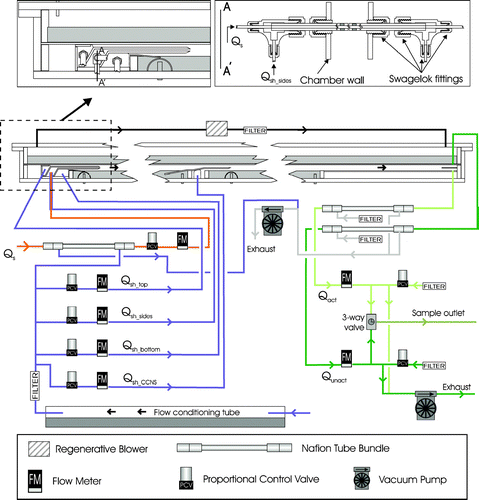
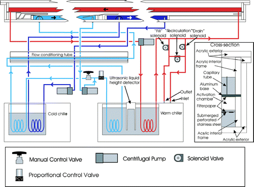
As discussed above and shown in , three water baths are used in the DAS. Temperature-controlled water (saline for the CCNS) is continuously pumped through the CCNR, CCNS, and upper baths. The temperature in each of the baths is measured using two YSI thermistors, which have a stated accuracy of ± 0.1°C. All six thermistors were calibrated together prior to installation. The open surfaces of the lower CCNR and CCNS baths provide a direct source of water vapor, while water in the upper bath is intermittently used to soak the filter paper adhered to the upper surface of the CCNR and CCNS chambers; all three are used to maintain constant and uniform temperature at the lower and upper surfaces of the chambers.
FIG 6 DAS water flow schematic. The red, light blue, and dark blue represent the upper, CCNR, and CCNS baths and accompanying closed loop circuits, respectively. Grey shading represents additional locations of water in the system unless otherwise noted.
Bath Design
Both the CCNS and CCNR baths are located at the base of the DAS, and are contained within open acrylic boxes, the walls of which are 2.54 cm tall × 1.27 cm thick acrylic strips that are cemented to the single acrylic sheet that serves as the base. The CCNR bath extends 51 cm between the two air inlets, while the CCNS bath extends 89 cm between the middle air inlet and the sample outlet. For the chamber orientation shown in , water is injected on the left side of both the CCNR and CCNS baths and is removed on the right.
As depicted in the inset of , the 0.32 cm thick aluminum base of the upper bath rests 1.9 cm above the surfaces of the CCNR and CCNS baths on top of 4.44 cm tall × 1.27 cm thick acrylic strips that are cemented to the DAS base. Aircraft-grade 7075 aluminum was selected for its strength and thermal conductivity. Both sides of the aluminum sheet were coated with a spray-on acrylic sealant to reduce corrosion. The upper water bath is contained within 5.08 cm tall acrylic strips that are attached and sealed to the aluminum sheet with a combination of screws and silicone glue. To prevent deflection of the bottom aluminum plate into the activation chamber, four 11.4 cm tall × 3.81 cm thick aluminum bars spanning the width of the bath are attached to the aluminum base. Several channels were cut out of the bottoms of the bars to minimize impedance of the water flow. The direction of the water flow in the upper bath is opposite of that in the CCNR and CCNS. This counter-current flow reduces lengthwise gradients in the supersaturation-producing temperature differentials that result from temperature relaxation in the water flows during passage through the baths.
Temperature Control
Temperature adjustment is achieved by continuously circulating the water from each of the baths in closed loop circuits through coils in temperature-controlled chiller reservoirs. Pumps inside each of the chillers circulate water around the submerged coils. The VWR model 1197P and 1187P chillers used in the instrument are identified as the cold and warm chillers in , respectively. It should be noted that these names describe only the relative temperatures, as even the warm chiller is kept below room temperature. As shown in that figure, water in the CCNS bath is continuously pumped through the cold chiller, while the water in the upper bath is continuously pumped through the warm chiller. Antimicrobial Tygon tubing is used to connect the baths, centrifugal pumps, and submerged coils. Labview-based proportional-integral-differential (PID) algorithms are used to continuously adjust the chiller reservoir temperatures to maintain the prescribed temperatures in the CCNS and upper baths.Footnote 1
As shown in , the water circulation loop for the CCNR bath, which is maintained at a temperature between that of the CCNS and upper baths, is connected to coils submerged in both the warm and cold chillers. In contrast to the technique employed to control temperatures in the CCNS and upper baths, temperature control of the CCNR bath is achieved through PID-adjustment of a Teknocraft proportional control valve that is inline with the warm chiller. Water temperature is increased as the valve is opened and more flow is directed through the warm chiller, and is decreased as the valve is closed and more flow follows the alternate path through the cold chiller. As shown in , prior to re-entering the CCNR bath, the merged water flow is directed through a 1.27 cm diameter stainless steel tube submerged in the water-filled acrylic cylinder used to humidify the sheath flow, as is described below.
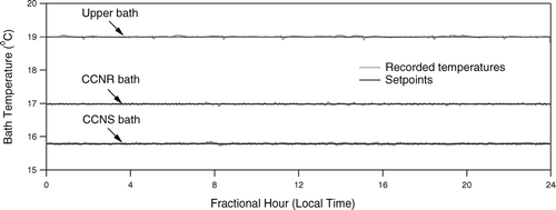
Following an initial 2–3 h period required to cool the combined 56 L of circulated water, the bath temperatures are tightly controlled to their prescribed setpoints. shows the stability of the bath temperatures over a 24 h period when the DAS was operated in Mexico City during the Megacities Impact on Regional And Global Environment—Mexico (MIRAGE—Mex) campaign.
Temperature Uniformity
Temperature gradients in the water baths broaden the Sc range of the separated aerosol as particles along different streamlines experience different peak supersaturations. Such gradients are minimized through insulation of the chamber walls as discussed above, and through a combination of measures designed to vigorously mix the baths without perturbing the air flows. Because the upper bath water surface is isolated from the air flows, temperature uniformity was more readily achieved through use of a powerful centrifugal pump capable of turning over the water volume roughly once per minute. The water in the upper bath is agitated as it first spills over an acrylic barrier immediately downstream of the injection point and is then forced through the series of channels cut into the aluminum support bars described above.
The centerline air velocity in the CCNR is typically less than 1 cm/s, which is necessary to provide sufficient time for droplets to grow and settle to the water bath below. The air velocity in the CCNS is slightly higher due to the introduction of additional sheath air. Such lazy flows are easily disturbed by any circulation in the lower baths. To minimize variability of the bath water velocity that could be caused by coupled jets and stagnant regions, water flows enter and exit the CCNR and CCNS baths through series of evenly spaced holes that extend the width of the chamber. Pumping rates through the CCNR and CCNS baths are sufficient to turn over the water volumes once per minute and once per two minutes, respectively. As depicted in the inset of , these flows are decoupled from the surface by sheets of filter paper that rest on sheets of perforated stainless steel located at a depth of only a few mm. The baths are further mixed through eight uniformly-spaced stirrer magnets that are positioned above variable-speed enclosure fans to which magnets are attached.
Water Delivery to the Filter Paper
Because the wetted filter paper adhered to the bottom of the upper bath is warmer than the CCNR and CCNS baths below, it slowly dries as water vapor diffuses downward due to the vapor pressure gradient. Rather than continuously supplying water to the filter paper, it is re-wetted at a specified interval that is sufficiently short to prevent any reduction in (Sp)CCNR and (Sp)CCNS. Typical intervals of 1 and 3 hours are used for operation at (Sp)CCNS = 0.7% and 0.175%, respectively. Water is supplied to the filter paper through 104 vertically oriented 0.57 mm ID capillary tubes that were inserted and sealed in evenly spaced holes drilled into the aluminum plate. The water level in the upper bath is adjusted using the on-off solenoid valves labeled “fill,” “recirculation,” and “drain” in . During normal operation, the water level in the upper bath is below the tops of the capillary tubes and the internal pump in the warm chiller circulates water in a loop created by opening only the recirculation solenoid valve. The filter paper is wetted by opening only the fill solenoid valve, thereby pumping water from the internal reservoir of the warm chiller into the upper bath. This continues until the upper bath water level rises sufficiently to submerge the capillary tubes, through which water drips and slowly wets the filter paper. The optimal peak water level in the upper bath is selected to fully soak the filter paper, while allowing only a minimal amount of water to drip through the filter paper into the lower baths, as any added water dilutes the CCNS solution. The level in the upper bath is monitored indirectly by measuring with a Microspan ultrasonic liquid level height detector the depth of water in the warm chiller reservoir, which is uniquely related to the level in the upper bath because water is only exchanged between the two. After the filter paper is wetted, only the drain solenoid valve is opened, which pumps water from the upper bath back into the warm chiller reservoir until it is filled to its initial level, after which the recirculation valve is again opened and normal operation is resumed.
Particles that originate in the volume of air above the upper water bath can migrate into the CCNR and CCNS through the capillary tubes or around the sides of the bath. To eliminate this potential source of contamination, the air above the upper bath is continuously circulated through a filter.
Air Flow
As discussed above, the sample flow, Qs, introduced into the CCNR is confined in a narrow ribbon that is separated from the CCNR bath, the filter paper, and the sides of the chamber by particle-free sheath flows identified as Qsh_bottom, Qsh_top, and Qsh_sides, respectively. It is then displaced upward in the CCNS through introduction of an additional particle-free sheath flow, Qsh_CCNS. At the chamber exit, the layer of unactivated particles near the top of the chamber and the layer of activated particles near the bottom are extracted in the Qunact and Qact flows, respectively. Each of these seven air flows is continuously monitored and independently controlled. The discussion below is separated into sections describing the design of the inlets and outlets, conditioning of the flows, and active control of the flows.
Inlet and Outlet Designs
The sample flow is introduced into both ends of a single 0.64 cm OD stainless steel tube that extends the width of the chamber, and exits through a series of 0.20 cm wide slits. The width of these slits was selected to produce a sufficient pressure drop to ensure uniform flow over the length of the tube. To minimize mixing between Qs and Qsh_sides that might result as the flow decelerates after exiting the tube, a tube-in-tube design depicted in was employed in which the narrow slits in the inner tube are directed towards the back of a 0.95 cm OD tube having a series of 0.51 cm wide slits. Also shown in the figure are the O-Rings that isolate Qs from Qsh_sides. That Qsh_sides flow is introduced into the annulus between the two tubes in the manner depicted in the upper right inset in . The Qs and Qsh_sides flows enter the CCNR section of the enclosure between parallel 6065 alloy aluminum plates as shown in the upper left inset of . Particle-free sheath flow is injected above the upper plate and below the lower plate to confine the sample near the centerline as described above and shown in . Both Qsh_top and Qsh_bottom are introduced behind Micropore porous stainless steel sheets, which distributes the flows uniformly along the length of the entrance ramp plates. The extension of these plates over the CCNR bath is designed to reduce the distance particles travel prior to reaching the steady-state S profile and to provide sufficient length to dampen any initial disturbances in the flows. The end of each of the plates is tapered to a knife edge to minimize turbulence at the point the three flows merge. This inlet design was tested by injecting smoke into the sample and visually monitoring its position in the CCNR section.
The sheath flow used to displace the flow upward between the CCNR and CCNS sections is introduced below a metal ramp and behind a Micropore sheet. As shown in , the left side of the ramp is submerged in the CCNR bath to minimize flow disturbances at the intersection and to maintain a roughly constant lower boundary temperature over the transition between the CCNR and CCNS. Because the Qsh_CCNS flow rate is typically about the same as that of the combined flow exiting the CCNR, the metal plate separating the two is positioned at a height roughly half way between the CCNS bath and the top of the chamber. As with the inlet ramp, the end of the metal plate is tapered to a knife edge to reduce mixing.
The Qact and Qunact flows are extracted through 0.95 cm diameter tubes that are flush with the lower and upper plates in the converging exit region of the chamber. The tubes are located near the vertex of those triangular plates. Separation of the two flows is aided by a thin metal sheet near the vertical midpoint that extends about 5 cm out from the vertex of the extraction region.
Conditioning of Inlet and Outlet Flows
To slow the rate at which the filter paper in the CCNR dries, and to reduce the distance required to develop the steady-state S profile, the sample and 4 sheath flows are humidified to RH > 95% at the temperature of the CCNR bath prior to introduction into the chamber. A single air flow that is subsequently split into the 4 sheath flows and an additional flow used to humidify the sample is directed through the 1.5 m long horizontal flow saturator tube shown in . Water from the CCNR bath is continuously pumped through this ∼ 2/3 full 8.9 cm ID double-walled acrylic cylinder. To eliminate variability in the water level in the CCNR bath that could result from changes in the level in the saturator, the two baths are decoupled by pumping the water through a stainless steel tube that is submerged in a sealed volume of water contained in the acrylic cylinder. Thus, the temperature of the saturator equilibrates with that of the CCNR bath as heat is exchanged with the circulated water. The humidified air exiting the saturator is filtered using a 0.22 μ m polypropylene filter. A portion of that flow is used as the purge flow surrounding a bundle of eighteen 1.8 mm OD Nafion tubes through which Qs is directed prior to entering the chamber. Equilibration of water vapor pressure across the Nafion tubes raises the RH of the sample flow to roughly that of the sheath flows.
Both the Qact and Qunact flows remain subsaturated after exiting the chamber enclosure because the water bath temperatures are always maintained below room temperature. To minimize inertial and impaction losses of the initially large haze droplets exiting the chamber, the flows are immediately dried to below 20% RH within Nafion tube bundles that are surrounded by purge flow that is under vacuum.
Flow Control
A total of five separate flows enter the DAS and two exit. Control of these flows is complicated by the fact that prescribed flow rates differ by a factor of 3 as (Sp)CCNS is varied over the typical operational range between 0.175% and 0.7%. Each of the five inlet flows is directed through a Teknocraft proportional control valve and an Alicat Scientific volumetric flow meter, and is controlled using a Labview-based PID control algorithm. The control software fully opens the valve for which the PID-determined control voltage is nearest that corresponding to full-open. This eliminates the scenario in which the independent PID controls maintain prescribed flows while slowly closing all five valves, which would result in an excessive vacuum within the chamber.
As depicted in , the Qact and Qunact flows are controlled indirectly using Teknocraft control valves to vary the amount of dilution flow added to each downstream of the connection to other instruments and upstream of a critical orifice that is connected to a Gast vacuum pump. As with the inlet flows, the voltages applied to the valves used to control Qact and Qunact are adjusted through Labview-based PID algorithms. The Qact and Qunact flows are connected to an electrically actuated 3-way ball valve, which permits automated sequential sampling of both particle populations.
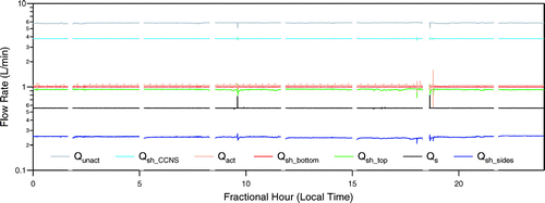
Because of short-term fluctuations in flow rates and inherent inaccuracies in the flow meters, the sum of the measured inlet flow rates may not always match that of the outlet flow rates. This precludes simultaneous control of all seven flow rates to fixed setpoints. Therefore, the inlet flows are independently controlled to their fixed setpoints, while the two outlet flows are controlled to a constant fraction of their sum, which itself is adjusted through a separate PID algorithm that maintains the prescribed total inlet flow. The ratio of the sum of the measured inlet flow rates to that of the outlet flow rates is continuously monitored to identify potential leaks in the system. illustrates the stability of the 7 flow rates over a 24 h period during the MIRAGE—Mex study. The breaks in each of the lines correspond to periods when the filter paper was re-wetted, during which all valves are fully opened because the inlet and outlet flows cannot be balanced as water is initially added and then removed from the fixed-volume enclosure.
INSTRUMENT CALIBRATION
The DAS was calibrated with a polydisperse ammonium sulfate aerosol generated with a TSI 3076 atomizer. The size distributions of the aerosol generated by the atomizer and of the activated aerosol extracted from the DAS were measured using a differential mobility analyzer (DMA). shows the results of calibrations performed for (Sp)CCNR/(Sp)CCNS = 0.15%/0.175%, 0.3%/0.35%, and 0.6%/0.7%. The peak heights of the separated aerosol size distributions have been adjusted to clearly show the location of the distributions relative to the atomizer output envelope. The shoulders on the left side of the distributions separated at lower S are caused by incorrect size assignment of multiply charged particles by the DMA. The data inversion employed during field operation minimizes such contributions by accounting for the probability particles will possess multiple charges. These single-component aerosol size distributions were translated into differential CCN spectra using Köhler Theory. The three calculated CCN spectra are shown in . The Sc array for each of those spectra is normalized relative to that at its peak, Sc*, to facilitate comparison of their shapes and widths. The resolution of the DAS, R, is defined as the ratio of Sc* to the width of the spectrum at half height. Neglecting any broadening in the retrieved distributions caused by the DMA, the limiting resolution for each of the three S ranges is
FIG 11 Size distributions of Sc-resolved ammonium sulfate aerosol measured using a differential mobility analyzer. The peak heights of the separated aerosol size distributions have been adjusted to clearly show the location of the distributions relative to the atomizer output envelope.
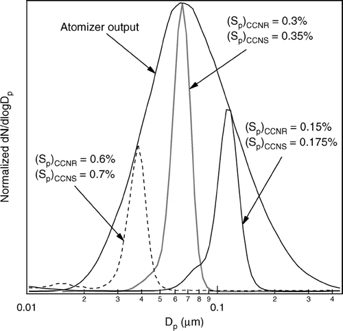
FIG 12 Distributions shown in translated into differential CCN spectra. The Sc array for each of those spectra is normalized relative to that at its peak, Sc*, to facilitate comparison of their shapes and widths.
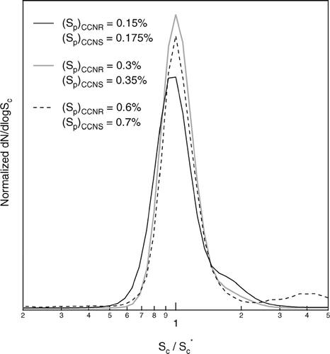
The values calculated from the calibration data were 3.8, 4.1, and 3.8 for the 0.15%/0.175%, 0.3%/0.35%, and 0.6%/0.7% Sp pairs, respectively. The achievable resolution is further reduced for operation at supersaturations below the 0.15%/0.175% minimum of these calibrations as separation of the activated particles in the CCNS is hampered by the limited difference in sizes, and consequently settling velocities, of the activated droplets and unactivated haze particles. Ongoing refinement of the inlet design and water circulation is aimed at narrowing the separation between the achievable and limiting resolution.
SUMMARY
A novel instrument has been developed that is designed to separate from a sampled aerosol only those particles having critical supersaturations in a narrow range. The separation is achieved through sequential removal of low Sc particles in a CCN remover (CCNR) and of high Sc particles in a CCN separator (CCNS). Both the CCNR and CCNS are continuous flow thermal gradient diffusion chambers, with the primary difference between the two being the use of pure water as the lower boundary of the CCNR and of a saline solution as the lower boundary of the CCNS. Unattended operation for several days is made possible through automated re-wetting of the filter paper that is the primary water vapor source, and through active control of the bath temperatures and air flow rates. The DAS has no integrated particle detector, but rather is designed to be operated upstream of an array of instruments that can characterize the physical and chemical properties of the Sc-resolved aerosol.
The DAS was calibrated by measuring the size distribution of the separated aerosol when a polydisperse ammonium sulfate aerosol was sampled. These calibration size distributions were translated into CCN spectra using Köhler Theory and used to quantify the DAS resolution, defined as the ratio of the Sc at the peak of the distribution to the full width at half height. The resolution calculated in this way is roughly 4 over the Sc range from roughly 0.16% to 0.65%. Data collected during the initial use of the DAS during the MIRAGE-Mex study in the spring of 2006 will be described in future publications.
Acknowledgments
This work was supported by the NSF Atmospheric Chemistry and Physical Meteorology Programs through grant ATM-0094342. Participation in the MIRAGE-Mex study was supported by the NSF Atmospheric Chemistry Program through grant ATM-0514401.
Notes
1The DAS control software is available at no cost from the corresponding author.
REFERENCES
- Ackerman , A. S. , Toon , O. B. , Taylor , J. P. , Johnson , D. W. , Hobbs , P. V. and Ferek , R. J. 2000 . Effects of Aerosols on Cloud Albedo: Evaluation of Twomey's Parameterization of Cloud Susceptibility using Measurements of Ship Tracks . J. Atmos. Sci. , 57 : 2684 – 2695 .
- Aitken , J. 1880a . On Dust, Fogs and Clouds . Proc. Royal Soc. Edinburgh. , 11 : 14 – 18 .
- Aitken , J. 1880b . On Dust, Fogs and Clouds . Nature , : 384 – 385 .
- Alofs , D. J. , Williams , A. L. , Hagen , D. E. , Medley , S. D. , White , D. R. and Schmitt , J. 1997 . A System for Collecting Milligram Quantities of Cloud Condensation Nuclei . Aerosol Sci. Technol. , 26 : 415 – 432 .
- Bilde , M. and Svenningsson , B. 2004 . CCN Activation of Slightly Soluble Organics: The Importance of Small Amounts of Inorganic Salt and Particle Phase . Tellus Series B—Chem. Phys. Meteorol. , 56 : 128 – 134 .
- Cantrell , W. , Shaw , G. , Cass , G. R. , Chowdhury , Z. , Hughes , L. S. , Prather , K. A. , Guazzotti , S. A. and Coffee , K. R. 2001 . Closure between Aerosol Particles and Cloud Condensation Nuclei at Kaashidhoo Climate Observatory . J. Geophys. Res.—Atmospheres. , 106 : 28711 – 28718 .
- Charlson , R. J. , Schwartz , S. E. , Hales , J. M. , Cess , R. D. , Coakley , J. A. , Hansen , J. E. and Hofmann , D. J. 1992 . Climate Forcing by Anthropogenic Aerosols . Science , 255 : 423 – 430 .
- Chuang , P. Y. , Charlson , R. J. and Seinfeld , J. H. 1997 . Kinetic Limitations on Droplet Formation in Clouds. . Nature , 390 : 594 – 596 .
- Chuang , P. Y. , Collins , D. R. , Pawlowska , H. , Snider , J. R. , Jonsson , H. H. , Brenguier , J. L. , Flagan , R. C. and Seinfeld , J. H. 2000 . CCN Measurements during ACE-2 and Their Relationship to Cloud Microphysical Properties . Tellus Series B—Chem. Phys. Meteorol. , 52 : 843 – 867 .
- Gasparini , R. , Collins , D. R. , Andrews , E. , Sheridan , P. J. , Ogren , J. A. and Hudson , J. G. 2006 . Coupling Aerosol Size Distributions and Size-Resolved Hygroscopicity to Predict Humidity-Dependent Optical Properties and Cloud Condensation Nuclei Spectra . J. Geophys. Res.—Atmospheres. , 111
- Harrison , L. and Harrison , H. 1985 . The Segregation of Aerosols by Cloud-Nucleating Activity 1. Design, Construction, and Testing of a High-Flux Thermal-Diffusion Cloud Chamber for Mass Separation . J. Climate and Appl. Meteorol. , 24 : 30 – 310 .
- Hegg , D. A. , Covert , D. S. , Jonsson , H. , Khelif , D. and Friehe , C. A. 2004 . Observations of the Impact of Cloud Processing on Aerosol Light-Scattering Efficiency . Tellus Series B—Chem. Phys. Meteorol. , 56 : 285 – 293 .
- Henning , S. , Rosenorn , T. , D'Anna , B. , Gola , A. A. , Svenningsson , B. and Bilde , M. 2005 . Cloud Droplet Activation and Surface Tension of Mixtures of Slightly Soluble Organics and Inorganic Salt . Atmos. Chem. Phys. , 5 : 575 – 582 .
- Hoegrefe , O. V. and Keesee , R. G. 2002 . Heterogeneous Vapor-to-Liquid Nucleation of Water on Individual Glass Particles . Aerosol Sci. Technol. , 36 : 239 – 247 .
- Ji , Q. , Shaw , G. E. and Cantrell , W. 1998 . A New Instrument for Measuring Cloud Condensation Nuclei: Cloud Condensation Nucleus “Remover,” . J. Geophys. Res.—Atmos. , 103 : 28013 – 28019 .
- Jones , A. , Roberts , D. L. , Woodage , M. J. and Johnson , C. E. 2001 . Indirect Sulphate Aerosol Forcing in a Climate Model with an Interactive Sulphur Cycle . J. Geophys. Res.—Atmos. , 106 : 20293 – 20310 .
- Liu , P. S. K. , Leaitch , W. R. , Banic , C. M. , Li , S. M. , Ngo , D. and Megaw , W. J. 1996 . Aerosol Observations at Chebogue Point during the 1993 North Atlantic Regional Experiment: Relationships among Cloud condensation Nuclei, Size Distribution, and Chemistry . J. Geophys. Res.—Atmos , 101 : 28971 – 28990 .
- Noone , K. J. , Ogren , J. A. , Heintzenberg , J. , Charlson , R. J. and Covert , D. S. 1988 . Design and Calibration of a Counterflow Virtual Impactor for Sampling of Atmospheric Fog and Cloud Droplets . Aerosol Sci. Technol. , 8 : 235 – 244 .
- Ogren , J. A. , Heintzenberg , J. and Charlson , R. J. 1985 . In situ Sampling of Clouds with a Droplet to Aerosol Converter . Geophys. Res. Lett. , 12 : 121 – 124 .
- Rosenfeld , D. 1999 . TRMM Observed First Direct Evidence of Smoke from Forest Fires Inhibiting Rainfall . Geophys. Res. Lett. , 26 : 3105 – 3108 .
- Shaw , R. A. and Lamb , D. 1999 . Experimental Determination of the Thermal Accommodation and Condensation Coefficients of Water . J. Chem. Phys. , 111 : 10659 – 10663 .
- Spracklen , D. V. , Pringle , K. J. , Carslaw , K. S. , Chipperfield , M. P. and Mann , G. W. 2005 . A Global Off-Line Model of Size-Resolved Aerosol Microphysics: I. Model Development and Prediction of Aerosol properties . Atmos. Chem. Phys. , 5 : 2227 – 2252 .
- Sun , L. K. and Reiss , H. 1984 . Measurement of the Properties of Single Aerosol Drops using a New Means of Suspension . J. Coll. Interface Sci. , 99 : 515 – 535 .
- Tang , I. N. and Munkelwitz , H. R. 1994 . Water Activities, Densities, and Refractive-Indexes of Aqueous Sulfates and Sodium-Nitrate Droplets of Atmospheric Importance . J. Geophys. Res.—Atmos. , 99 : 18801 – 18808 .
- Twomey , S. 1977 . Influence of Pollution on Shortwave Albedo of Clouds . J. Atmos. Sci. , 34 : 1149 – 1152 .
- VanReken , T. M. , Rissman , T. A. , Roberts , G. C. , Varutbangkul , V. , Jonsson , H. H. , Flagan , R. C. and Seinfeld , J. H. 2003 . Toward Aerosol/Cloud Condensation Nuclei (CCN) Closure during CRYSTAL-FACE . J. Geophys. Res.—Atmos. , 108
- VanReken , T. M. , Ng , N. L. , Flagan , R. C. and Seinfeld , J. H. 2005 . Cloud Condensation Nucleus Activation Properties of Biogenic Secondary Organic Aerosol . J. Geophys. Res.—Atmos. , 110
