Abstract
A simple and novel unipolar charger using carbon fiber ionizers was developed to effectively charge fine and ultra-fine aerosol particles without the generation of ozone. The particle penetration in the charger was investigated for non-charged, neutralized, and singly charged particles in the size range of 20–200 nm. Particle loss and the intrinsic, exit and extrinsic charging efficiencies of fine and ultra-fine particles were also investigated for non-charged particles at different applied voltages to the charger. Particle penetrations in the charger were nearly 100% for particles larger than 20 nm, irrespective of the initial particle charging state. Particle losses in the charger could be decreased by decreasing the applied voltage to the charger from 4.0 kV to 2.3 kV. The intrinsic charging efficiencies were proportionally increased with the applied voltage, whereas the exit charging efficiencies were almost independent of the applied voltage. Therefore, the extrinsic charging efficiency of the charger becomes higher for the lower applied voltage (2.3 kV), at which about 60% of 20 nm particles were charged. Little (less than 4 ppb) to no ozone was generated under all operation conditions. It can be concluded that the newly developed unipolar charger using carbon fiber ionizers can charge fine and ultra-fine particles at least as effectively as currently available unipolar chargers, but with the major advantage of negligible ozone generation, a highly desirable feature if the charged particles are to be used for chemical or biological analysis.
INTRODUCTION
Particle charging has become an effective way to control the behavior of particles in transport and deposition processes. Charged particles can be easily manipulated according to their mobility in an adjustable electric field. One of oldest, most important and most commonly used methods to classify particles according to their size using a differential mobility analyzer (DMA) is based on particle charging (CitationKnutson and Whitby 1975; CitationKousaka et al. 1985). Meanwhile, there has been a growing focus on the direct position or deposition pattern of particles in the manufacturing of photonic or quantum electronic devices. In industrial processes, particle charging is essential in enabling us to move and deposit particles on desired spots (CitationKrinke et al. 2001; CitationJacobs et al. 2002; CitationKang et al. 2004; CitationKim et al. 2006).
Unipolar charging has typically a higher particle charging efficiency than bipolar charging because the recombination of charged particles with the opposite polarity ions can be prevented (CitationAdachi et al. 1985). However, using the charged particles in many applications may become problematic because of the high electrostatic losses that would likely occur in the charger and sampling lines (CitationAdachi et al. 1987).
Corona discharge has been widely used to acquire unipolar charged particles, since this technique can easily generate a high number concentration of unipolar ions (CitationBurtscher et al. 1994; CitationKruis and Fissan 2001; CitationBiskos et al. 2005). Nonetheless, this mechanism produces ozone and may generate particles by the erosion of the discharging electrodes. Ozone generated in the corona discharger is of particular concern, as it may alter the chemical and microphysical properties of the charged particles by means of chemical reactions involving particle-bound organic components, such as polycyclic aromatic hydrocarbons and alkanes (CitationEliason et al. 2003; CitationKatrib et al. 2004).
Radioactive materials have also been used for unipolar charging of aerosol particles. Radioactive sources such as 241Am and 210Po are used for the production of stable unipolar ions by applying an electric field to the chamber with the radioactive source, thus separating the positive and negative ions (CitationAdachi et al. 1985; CitationChen and Pui 1999). However, considerable control must be exercised over this method because of the possibility of radioactive leaks.
The discussion in the previous paragraphs outlines the need for new, simpler and safer particle chargers that do not generate ozone and-or other particles. As an alternative to radioactive sources and corona discharge, soft X-ray has been attempted as a mechanism for particle charging (CitationShimada et al. 2002; CitationHan et al. 2003). Soft X-ray chargers can generate high numbers of stable ions, and thus have a higher particle charging capacity than radioactive chargers (CitationHan et al. 2003). However, they utilize expensive and complicated soft X-ray generators and controllers. More recently, a surface-discharge microplasma aerosol charger (SMAC) was developed for bipolar and unipolar charging of aerosol particles (CitationKwon et al. 2006, Citation2007). The unipolar SMAC achieved low particle loss and high charging efficiency without the use of sheath air in the particle size range of 3–15 nm (CitationKwon et al. 2007). However, chargers using surface-discharge plasma may generate ozone as well as particulate matter (CitationKwon et al. 2006).
Carbon fiber ionizers can be easily and inexpensively developed by applying a few kV to a bundle of carbon fibers to generate ions. They can produce stable unipolar ions in sufficiently high concentrations, without generating particulate matter and ozone, and thus, they have been used in indoor air purifiers to generate negative ions as an alternative to corona discharge (CitationChen et al. 2006). Such a technique can be easily used to generate high number concentrations of both stable positive or negative gaseous ions for charging aerosol particles. To the best of our knowledge, we are not aware of any previous attempts to study unipolar charging of ultrafine aerosol particles using these carbon fiber ionizers.
In the present work, a novel unipolar charging device using carbon fiber ionizers was developed, and its performance characteristics, including particle penetration, particle loss during particle charging, intrinsic and extrinsic charging efficiency, were investigated. Intrinsic charging efficiencies of the unipolar charger were compared to the calculated data based on diffusion charging theory. The extrinsic charging efficiency of the unipolar charger was compared to that of the existing unipolar chargers in other previous studies as well.
UNIPOLAR DIFFUSION CHARGING THEORY
The diffusion charging of aerosol particles induced by unipolar ions can be expressed as follows (CitationAdachi et al. 1985):
For the value of β, Fuchs' limiting sphere theory (CitationFuchs 1963) was used. The Fuchs theory is most commonly used for the diffusion charging of particles in the transient regime and many of previously published studies on unipolar charging have supported its validity (CitationAdachi et al. 1985; CitationPui et al. 1988; CitationChen and Pui 1999; CitationBiskos et al. 2005; CitationKwon et al. 2006). The equation for combination coefficient, β based on Fuchs theory is as follows:
The subscript p indicates the number of the elementary charges and their polarity. C i, D i, and m i are the thermal velocity, diffusion coefficient and mass of an ion, respectively. k, T, and a are the Boltzmann constant, absolute temperature, and particle radius, respectively. φ and r represent the electrostatic potential of the ion and particle, and the distance between the centers of the particle and ion, respectively. ϵ 0 and ϵ 1 are the vacuum permittivity and the dielectric constant of the particle, respectively. σ is the radius of the limiting sphere, and is a function of the mean free path of the ion, λ i. α is the fraction of ions entering the limiting sphere that reach the particle surface, expressed as the ratio of minimum impact parameter, b m and the radius of the limiting sphere, σ. L m is the minimum apsoidal distance. β p depends significantly on the ion properties such as C i, D i, and λ i, which can be derived using the mass, m i and electrical mobility, Z i of ions as follows:
EXPERIMENTAL SETUP
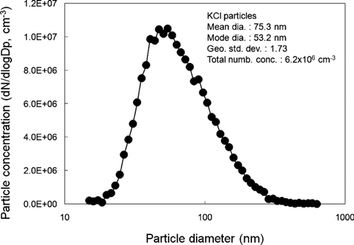
shows the unipolar aerosol charger using carbon fiber ionizers developed in this study. The carbon fiber ionizer consisted of a bundle of approximately 300 carbon fibers. The diameter of each carbon fiber is about 5–10 μ m and the carbon phase is graphite. The bundle of carbon fibers was connected with a SUS rod with a crimp socket connector, which was covered with a heat shrinkable tube. A positive D.C. voltage of 2.3–4.0 kV is applied to the carbon fiber ionizers with a high voltage power supply. Two carbon fiber ionizers are vertically placed on the upper and lower side of the inner wall of the charger, and fixed inside a cylindrical Teflon housing for electrical insulation. The Teflon housing is connected at both sides to two stainless steel cylinders having circular cone-shaped inlet and outlets, respectively. The outlet body is made longer than the inlet to allow for sufficient mixing of the incoming particles with the generated unipolar ions in the charging zone. shows the experimental setup used for measuring the penetration of singly charged, neutralized and non-charged particles in the unipolar charger. Potassium chloride (KCl) aerosol particles with diameters in the range 10–500 nm were generated by nebulizing KCl solution (w/w 0.1% in water) with an atomizer (Model 3076, TSI Inc., St. Paul, MN) and passed through a diffusion drier (Model 3062, TSI Inc., St. Paul, MN). The mean diameter, number concentration and geometric standard deviation of the generated particles were 75.3 nm, 6.2 × 10⁶ particles/cm3 and 1.73, respectively, as shown in . The particles were suspended in a N2 carrier gas, at a flow of 1.5 l/min and then passed through a 241Kr neutralizer (Model 3012, TSI Inc., St. Paul, MN) before being introduced into a differential mobility analyzer (DMA; Model 3071, TSI Inc., St. Paul, MN) with sheath air flow of 15 l/min. The particles exiting the DMA at a given voltage were nearly singly charged monodisperse particles. The fraction of multiply charged large particles exiting the DMA was reduced to about 10% or less for all particles in the size range of 20–200 nm by having the particle size distribution of the test aerosol centered around a mode diameter of about 50 nm. In some of the experiments, the singly charged particles were used as a test aerosol by themselves. In other tests, these particles were introduced into a 241Am neutralizer, followed by a parallel plate electrostatic precipitator (ESP) to which a D.C. high voltage of about 6.0 kV is applied. With the high voltage on the ESP on and off, non-charged and neutralized particles can be generated, respectively. Singly charged, non-charged, and neutralized monodisperse particles were then introduced into the unipolar charger. Particle concentrations were measured upstream (n 1) and downstream of the charger (n 2) without a voltage applied to the charger. The particle penetration (P) can be obtained by the following equation:
FIG. 1 Schematic of the unipolar charger using carbon fiber ionizers developed in this study. All dimensions are in mm except of the ID of the inlet and outlet ports and the SUS rod that are in inches.
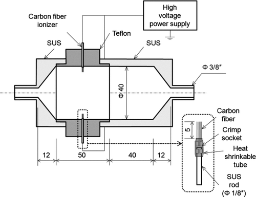
FIG. 2 Schematic of the experimental setup for the measurement of particle penetration.
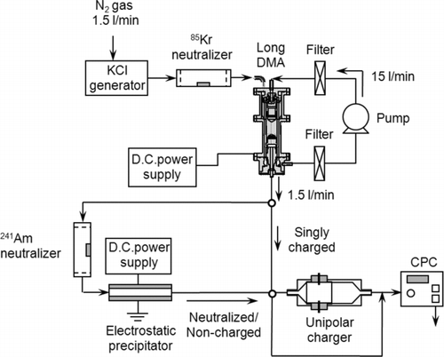
FIG. 3 Size distribution of the KCl particles generated from a nebulizer.
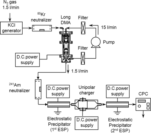
shows the schematic diagram of the experimental setup used for measuring the particle loss, intrinsic and extrinsic charging efficiencies of the unipolar charger. The non-charged particles generated by the above method are drawn through a second electrostatic precipitator (2ndESP) and a condensation particle counter (CPC; Model 3022A, TSI Inc., St. Paul, MN). Particle concentrations were measured without any voltage applied to either the unipolar charger or the 2ndESP (n 2), with voltage applied to the unipolar charger but not to the 2ndESP (n 3), and with voltages applied to both the unipolar charger and the 2ndESP (n 4). The particle loss during particle charging (L), intrinsic (ηint), exit (η exi) and extrinsic charging efficiency (η ext) can be expressed as follows:
FIG. 4 Schematic of the experimental setup for the measurement of particle loss, intrinsic and extrinsic charging efficiency.
RESULTS AND DISCUSSION
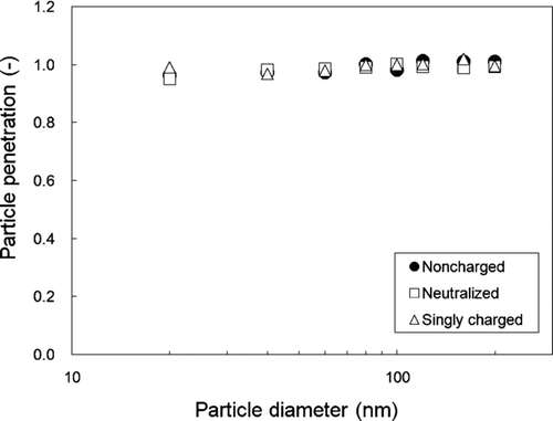
Particle Penetration Without Charging
The particle penetration of non-charged, neutralized and singly charged particles is shown in as a function of particle size. Almost 100% of particles in the 20–200 nm range penetrate the charger without any losses, regardless of their initial charging state. This result indicates that Brownian diffusion loss and space charge effects are negligible in the charger for particles larger than 20 nm. High particle penetration could be achieved even without the use of sheath air flow. The penetration of charged particles was consistently about 100% in the 20–200 nm range after long-term operations with the charger on (more than 1 month), which indicates that the insulator in the charger has a negligible influence on particle losses inside the charger.
FIG. 5 Particle penetration of singly charged, neutralized and non-charged particles in the unipolar charger.
Variation of Particle Concentration During Particle Charging
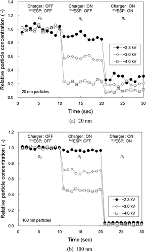
shows the relative particle concentration monitored with time at the outlet of the unipolar charger followed by the 2nd ESP for (a) 20 and (b) 100 nm particles. For first 10 seconds, no voltage was applied to either the unipolar charger or the 2nd ESP (n 2). After 10 seconds, a voltage of 2.3, 3.0, and 4.0 kV is applied to the unipolar charger (n 3) and after 20 seconds, a voltage of 6.0 kV is applied to the 2nd ESP (n 4). The ideal charger would show no drop in particle concentration with the charger turned on, and a drop to zero levels with the 2nd ESP on (i.e., no particle loss and 100% charging efficiency). However, all unipolar chargers suffer from particle loss within the charger due to electrostatic effects as soon as particles become charged. To minimize these losses, a sheath gas flow is usually applied to most unipolar chargers (CitationAdachi et al. 1985; CitationBurtscher et al. 1994; CitationChen and Pui 1999), which is, nonetheless, undesirable in cases where high concentrations are needed, because the sheath flow dilutes the concentration of charged particles exiting the charger. In this study, we applied relatively low voltages of 2.3–4.0 kV on the charger without the use of sheath air, to minimize the electric field formed. As seen in Fig 6a, the decrease in concentration of 20 nm particles with the charger on at 3.0 and 4.0 kV is similar and much higher than those with the 2nd ESP on. This indicates that most of the exiting particles are lost in the charger during the charging process. For an applied voltage of 2.3 kV, the concentration decrease with the charger on is considerably reduced when compared to those at higher voltages. The lower voltage results in low particle loss and high charging efficiency for the larger particles (100 nm), as seen in . The decrease in concentration with the charger on (2.3 kV) is almost negligible, whereas particle concentration reaches a near zero value with the 2nd ESP on. This means that most of the 100 nm particles penetrate the charger and are efficiently charged, which is close to the ideal case.
FIG. 6 The variation of relative particle concentration for: (a) 20 and (b) 100 nm particles after a high voltage is applied to the unipolar charger (2.3, 3.0, and 4.0 kV) and to the 2nd ESP (6.0 kV).
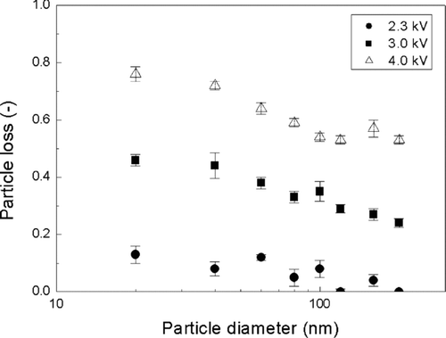
Particle Loss During Charging
shows the particle losses in the charger as a function of particle size during charging with an applied voltage ranging from 2.3–4.0 kV. Particle loss increases with decreasing particle size due to the higher electrical mobility of smaller particles. It also increases with the applied voltage on the charger due to the higher electric field formed in the charger, in direct proportion to the applied voltage. The particle loss for 20 nm is approximately 45% and 76% at 3.0 and 4.0 kV, respectively. However, at the lower voltage of 2.3 kV, which is still sufficient to generate ions for particle charging, the loss drops to about 12% for 20 nm particles. This value is well within the range of particle losses reported in previous charger designs, using sheath air flow.
FIG. 7 Particle losses in the unipolar charger as a function of particle size.
Intrinsic and Exit Charging Efficiency
and show the intrinsic and exit charging efficiency of the charger as a function of particle size in the 20–200 nm range, respectively. Decreasing the particle size leads to a decrease in the intrinsic charging efficiency due to the lower collision probability of smaller particles with ions. A higher applied voltage leads to a higher intrinsic charging efficiency because it produces a higher concentration of ions in the charger. However, even increasing the applied voltage to the charger does not increase significantly the exit charging efficiency, as shown in . This indicates that the charged state of the particles exiting the unipolar charger is almost independent of the applied voltage as long as the voltage is above a threshold value that is sufficient to initiate ion generation (here, 2.3 kV) due to the loss of ions in the charger. Unipolar charging is dominated by the product of ion number concentration, N, and charging time, t (Nt), and the charging time in the charger is constant for all the experiments. Theoretical calculations based on diffusion Fuchs charging theory (CitationFuchs 1963) were conducted and compared with the experimental data (also shown in and ). Nt was predicted from the fit between the calculated and experimental data. For mass and mobility of positive ions, we used the values of 130 amu and 1.1 cm2/Vs, borrowed from previous studies (CitationShimada et al. 2002; CitationHan et al. 2003). shows the properties of positive ions used in our theoretical calculations. The resulting values of Nt are 4.4, 6.5, and 9.6 × 10¹² m− 3· sec for applied voltages of 2.3, 3.0, and 4.0 kV, respectively, for the intrinsic charging efficiency, and 3.5 × 10¹² m-3· sec, independently of the applied voltage, for the exit charging efficiency, as seen in and . The theoretical predictions based on these values of Nt are in quite good agreement with the experimentally obtained data.
FIG. 8 (a) Intrinsic and (b) exit charging efficiency of the unipolar charger as a function of particle size and comparison with calculated charging efficiency based on the Fuchs theory (1963).
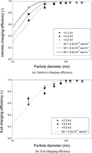
TABLE 1 Ion properties of positive ions
Extrinsic Charging Efficiency
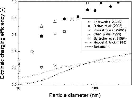
shows the extrinsic charging efficiency as a function of particle size for applied voltages of 2.3, 3.0, and 4.0 kV, respectively. The extrinsic charging efficiency decreases with increasing voltage values, because the increase in particle loss is much higher than that for the intrinsic charging efficiency with increasing applied voltage values. Therefore, the extrinsic charging efficiency for the unipolar charger at 2.3 kV is much higher than those at 3.0 and 4.0 kV. Extrinsic charging efficiency of about 60% is achieved for 20 nm particles at 2.3 kV. For comparison purposes, our extrinsic charging efficiency results at 2.3 kV are displayed in along with those of other unipolar and bipolar chargers developed by previous investigators. The results of CitationChen and Pui (1999) were obtained on a particle number basis, and thus, they were plotted in after dividing by 4 (i.e., the dilution ratio of that study) so that we could compare them on a particle concentration basis. Our charger shows a considerably higher charging efficiency than those obtained from the bipolar charging theory of CitationHoppel and Frick (1986) and Boltzmann distribution (the charging efficiency of 20 nm particles in bipolar charging is about 14.0% and 5.2%, based on Hoppel and Frick theory and the Boltzmann distribution, respectively), and also nearly equivalent performance to those of existing high efficiency unipolar chargers.
FIG. 9 Extrinsic charging efficiency of the unipolar charger as a function of particle size.
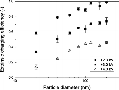
FIG. 10 Comparison of the extrinsic charging efficiency of this study (at 2.3 kV) with other previous experimental results as well as with that of the bipolar charging theory.
Ozone Emission
The concentrations of ozone were measured by means of a UV photometric ozone monitor (Model 400E, API, San Diego, CA) at the outlet of the charger, as shown in . For the ozone experiments measurements, ambient air was introduced into the charger instead of N2 gas. Ozone is a byproduct of corona discharge in air and may alter the chemical composition of particles sampled by means of electrostatic precipitators (ESP). According to previous studies (CitationArnold et al. 1997; CitationVolckens and Leith 2002), high voltage electrical fields and corona discharges are known to generate ozone and oxidant ions, such as O2 +, O+, N2 +, N+, NO+, and H3O+. Ozone and oxidant ions production by corona discharge depend on a number of factors, including the sampling flow rate, relative humidity, material, and diameter of corona wire as well as the operational voltage and polarity of a corona (CitationCardello et al. 2002; CitationGoheen et al. 1984; CitationKulkarni et al. 2002). These species have the potential to react with both particles and vapors that enter the plasma region. Degradation of particle-bound compounds by these reactions may limit or even preclude the use of devices using electrostatic charging as a sampler of atmospheric particulate matter.
FIG. 11 Ozone concentration as a function of the applied voltage at the outlet of the unipolar charger.
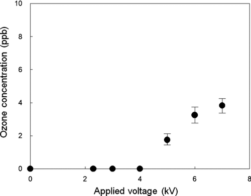
Our experiments showed that the ozone concentrations were below the limit of detection (0.6 ppb) of the O3 monitor for the 2.3–4.0 kV voltage range. Detectable ozone concentrations were measured at 5.0 kV, and the concentration reached about 4 ppb at 7.0 kV, a level that should still be considered negligible by the standards of most commonly used electrostatic chargers. We view this as one of the most promising features of this charger compared to the existing corona chargers, especially in utilizing it in the study of atmospheric aerosols.
The exact mechanism for the negligible ozone production by carbon fibers remains unclear, even though carbon fiber ionizers have been widely used in commercial air purifiers as an alternative to the ozone-producing corona discharge. Unlike existing corona dischargers, carbon fiber ionizers generate ions in open air flow even without a ground electrode. Because of their very small diameter of about 5–10 μ m, it is conceivable that the electric field at the tip of carbon fiber becomes high enough to generate corona discharge at a relatively low applied voltage compared to corona chargers, but still low enough not to generate high amounts of ozone. Clearly further investigations on this topic are warranted, but are beyond the scope of this article.
CONCLUSIONS
We developed a new unipolar charger based on carbon fiber ionizers. The performance of the charger has been evaluated experimentally for fine and ultra-fine particles in the range of 20–200 nm. The experimental data were compared to those of existing unipolar chargers. We found that the unipolar charger using carbon fiber ionizers could charge fine and ultra-fine particles as effectively as existing corona chargers, with the added advantage of generating little or no ozone, depending on the applied voltage. Therefore, this is a promising method for particle charging, especially in applications involving sampling and collection of atmospheric aerosols, often rich in organic compounds, which could be degraded by reactions with ozone and other radicals and ions produced by corona chargers.
Acknowledgments
This work was supported in part by a Basic Research Fund (NK134B) of the Korea Institute of Machinery and Materials (KIMM) and the Korea Research Foundation Grant funded by the Korean Government (MOEHRD) (KRF-2007-611-D00003). Additional funding was provided by the Southern California Particle Center (SCPC), funded by EPA under the STAR program through Grant RD-8324-1301-0 and the Xenobiotics, Oxidative Stress and Allergic Inflammation Center, funded by the National Institute of Allergy and Infectious Diseases–NIH grant AI070453. The research described herein has not been subjected to the agency's required peer and policy review and therefore does not necessarily reflect the views of the agency, and no official endorsement should be inferred. Mention of trade names or commercial products does not constitute an endorsement or recommendation for use.
REFERENCES
- Adachi , M. , Kousaka , Y. and Okuyama , K. 1985 . Unipolar and Bipolar Diffusion Charging of Ultrafine Aerosol Particles . J. Aerosol Sci. , 16 : 109 – 123 .
- Adachi , M. , Okuyama , K. , Kousaka , Y. , Kozuru , H. and Pui , D. Y. H. 1987 . Diffusion Charging of Ultrafine Aerosol Particles by Positive Helium, Argon, and Nitrogen Ions . J. Appl. Phys , 62 : 3050 – 3052 .
- Arnold , S. T. , Viggiano , A. A. and Morris , R. A. 1997 . Rate Constants and Branching Ratios for the Reactions of Selected Atmospheric Primary Cations with N-octane and Isooctane (2,2,4-trimethylpentane) . J. Phys. Chem. , 101 : 9351 – 9358 .
- Biskos , G , Reavell , K. and Collings , N. 2005 . Unipolar Diffusion Charging of Aerosol Particles in the Transition Regime . J. Aerosol Sci. , 36 : 247 – 265 .
- Burtscher , P. , Schmidt-Ott , A. and Wiedensohler , A. 1994 . Performance of a Unipolar “Square Wave” Diffusion Charger with Variable Nt-product . J. Aerosol Sci. , 25 : 651 – 663 .
- Cardello , N. , Volckens , J. , Tolocka , M. P. , Wiener , R. and Buckley , T. J. 2002 . Performance of a Personal Electrostatic Precipitator Particle Sampler . Aerosol Sci. Technol. , 36 : 162 – 165 .
- Chen , C. H. , Huang , B. R. , Lin , T. S. , Chen , I. C. and Hsu , C. L. 2006 . A New Negative Ion Generator Using ZnO Nanowire Array . J. Elctrochem. Soc. , 153 : G894 – G896 .
- Chen , D. R. and Pui , D. Y. H. 1999 . A High Efficiency, High Throughput Unipolar Aerosol Charger for Nanoparticles . J. Nanoparticle Res. , 1 : 115 – 126 .
- Eliason , T. L. , Aloisio , S. , Donaldson , D. J. , Cziczo , D. J. and Vaida , V. 2003 . Processing of Unsaturated Organic Acid Films and Aerosols by Ozone . Atmos. Environ. , 37 : 2207 – 2219 .
- Fuchs , N. A. 1963 . On the Stationary Charge Distribution on Aerosol Particles in a Bipolar Ionic Atmosphere . Geofis. Pura Appl. , 56 : 185 – 193 .
- Goheen , S. C. , Larkin , E. C. and Bissell , M. G. 1984 . Ozone Produced by Corona Discharge in the Presence of Water . Int. J. Biometeorol. , 28 : 157 – 161 .
- Han , B. , Shimada , M. , Choi , M. and Okuyama , K. 2003 . Unipolar Charging of Nanosized Aerosol Particles using Soft X-ray Photoionization . Aerosol Sci. Technol. , 37 : 330 – 341 .
- Hoppel , W. A. and Frick , G. M. 1986 . Ion-Aerosol Attachment Coefficients and the Steady-State Charge Distribution on Aerosols in a Bipolar Ion Environment . Aerosol Sci. Technol. , 5 : 1 – 21 .
- Jacobs , H. O. , Campbell , S. A. and Steward , M. G. 2002 . Approaching Nanoxerography: The Use of Electrostatic Forces to Position Nanoparticles with 100 nm Scale Resolution . Adv. Mater. , 14 : 1553 – 1557 .
- Kang , M. , Kim , H. , Han , B. , Suh , J. , Park , J. and Choi , M. 2004 . Nanoparticle Pattern Deposition from Gas Phase onto Charged Flat Surface . Microelectron. Eng. , 71 : 229 – 236 .
- Katrib , Y. , Martin , S. T. , Rudich , Y. , Davidovits , P. , Jayne , J. T. and Worsnop , D. R. 2004 . Density Changes of Aerosol Particles as a Result of Chemical Reaction . Atmos. Chem. Phys. Discuss. , 4 : 6431 – 6472 .
- Kim , H. , Kim , J. , Yang , H. , Suh , J. , Kim , T. , Han , B. , Kim , S. , Kim , D. S. , Pikhitsa , P. V. and Choi , M. 2006 . Parallel Patterning of Nanoparticles via Electrodynamic Focusing of Charged Aerosols . Nat. Nanotechnol. , 1 : 117 – 121 .
- Knutson , E. O. and Whitby , K. T. 1975 . Aerosol Classification by Electric Mobility: Apparatus, Theory and Applications . J. Aerosol Sci. , 6 : 443 – 451 .
- Kousaka , Y. , Okuyama , K. and Adachi , M. 1985 . Determination of Particle Size Distribution of Ultrafine Aerosol using a Differential Mobility Analyzer . Aerosol Sci. Technol. , 4 : 209 – 225 .
- Krinke , T. J. , Fissan , H. , Deppert , K. , Magnusson , M. H. and Samuelson , L. 2001 . Positioning of Nanometer-Sized Particles on Flat Surfaces by Direct Deposition from the Gas Phase . Appl. Phys. Lett. , 78 : 3708 – 3710 .
- Kruis , F. E. and Fissan , H. 2001 . Nanoparticle Charging in a Twin Hewitt Charger . J. Nanoparticle Res. , 3 : 39 – 50 .
- Kulkarni , P. , Namiki , N. , Otani , Y. and Biswas , P. 2002 . Charging of the Particles in Unipolar Coronas Irradiated by in-situ Soft X-ray: Enhancement of Capture Efficiency of Ultrafine Particles . J. Aerosol Sci. , 33 : 1279 – 1296 .
- Kwon , S. B. , Sakurai , H. , Seto , T. and Kim , Y. J. 2006 . Charge Neutralization of Submicron Aerosols using Surface-Discharge Microplasma . J. Aerosol Sci. , 37 : 483 – 499 .
- Kwon , S. B. , Sakurai , H. and Seto , T. 2007 . Unipolar Charging of Nanoparticles by the Surface-Discharge Microplasma Aerosol Charger (SMAC) . J. Nanoparticle Res. , 9 : 621 – 630 .
- Pui , D. Y. H. , Fruin , S. and McMurry , P. H. 1988 . Unipolar Diffusion Charging of Ultrafine Aerosols . Aerosol Sci. Technol. , 8 : 173 – 187 .
- Shimada , M. , Han , B. , Okuyama , K. and Otani , Y. 2002 . Bipolar Charging of Aerosol Nanoparticles by a Soft X-ray Photoionizer . J. Chem. Eng. Jpn. , 35 : 786 – 793 .
- Volckens , J. and Leith , D. 2002 . Filter and Electrostatic Samplers for Semivolatile Aerosols: Chemical Artifacts . Environ. Sci. Technol. , 36 : 4608 – 4612 .