Abstract
This article reports a method to produce airborne particles by generating uniformly sized droplets that contain particles, where the droplets are made with an acoustic ejector that does not need any small orifice or nozzle which might become clogged. We demonstrate stable and continuous ejection for more than 10 minutes of 14-μ m droplets containing 1-μ m polystyrene latex (PSL) particles at a concentration of 1% solids. There was no indication of clogging. We have demonstrated ejection of droplets containing PSL at rates up to 3,000 droplets/s (90,000 1-μ m-PSL particles/s). This method should produce, at a known rate, (1) uniform particles of known volume when the particles are soluble in the liquid and/or (2) particles with a statistical distribution (e.g., Poisson distribution) when the particles are aggregates of primary particles. The method should be useful for aerosol generation systems requiring no volatile organic compounds (VOC).
1. INTRODUCTION
Ink-jet printing has attracted a large interest for applications outside its conventional use in printing text and graphics, especially as a manufacturing technology for fabrication of biochemical microarrays (CitationLausted et al. 2004), 3-D microelectromechanical systems (CitationFuller et al. 2002), and microelectronic components (CitationHebner et al. 1998). Recently, technologies developed for ink-jet printing have also been used to produce aerosol particles for developing and testing instrumentation for studying and monitoring indoor and atmospheric aerosols, including harmful aerosols such as bacteria, pollens, or combustion aerosols; for testing aerosol protection or control equipment (e.g., filters, protective masks, air cleaning systems); and for pharmaceutical dispensing applications (CitationBottiger et al. 1998; CitationPan et al. 2003; CitationSchafer et al. 2007; CitationDavitt et al. 2005). For such applications it is often very useful to be able to generate, at a desired rate or in a droplet-on-demand mode, droplets or particles having a specific, monodisperse size. For some applications, e.g., testing and verifying the performance of aerosol measurement systems (CitationNoble and Prather 2000; CitationEversole et al. 1999; CitationHybl et al. 2006; CitationPan et al. 2007), the test particles may be difficult to obtain, expensive, or toxic, and so generation systems that can operate with very small volumes of material are desired. In this article we are specifically interested in the generation, in a droplet-on-demand mode, of highly monodisperse droplets and particles.
Among the ink-jet printing methods for aerosol manufacturing, the ink jet aerosol generator (IJAG) (CitationBottiger et al. 1998; CitationPan et al. 2003) and MicroDrop (CitationSchafer et al. 2007; CitationDavitt et al. 2005) are the two most commonly used droplet-based aerosol generators. With the IJAG, thermal actuation is utilized. Droplets are ejected from a nozzle through the growth and collapse of vapor bubbles created by a heater. In the MicroDrop piezoelectric method, a hydrostatic pressure produced by the mechanical contraction of a piezoelectric tube forms a droplet through the nozzle orifice. A 256-element array of piezoelectric nozzles has been used to generate aerosols (CitationDougherty et al. 2007). Although the two methods have been used to produce populations of particles, they both use an orifice to define the size of the ejected droplets and thus suffer from the inherent tendency of orifices to be clogged by particles in the liquid. Clogging becomes especially problematic when tiny droplets are desired, because tiny orifices are required to eject tiny droplets. Ejectors used in ink-jet printers typically have orifice diameters in the range of 20 μ m to 70 μ m (CitationReis et al. 2005a). Smaller orifices are more difficult to construct with good uniformity. Tiny droplets can be advantageous because: (a) non-volatile impurities in the droplets are concentrated as a droplet dries (e.g., when a 50-μ m droplet dries to leave a 1-μ m particle, impurities in the droplet are concentrated 125,000 times in the resulting particle), and (b) tiny droplets can evaporate much more rapidly in air, and so less (or no) heating of the droplets is required. Also, because of the undesirable satellite droplets produced using orifice-based ejection with the IJAG, a tight control of the air flow is required to effectively sweep out satellite droplets (CitationPan et al. 2003). With the IJAG, even when the airflow is well controlled, there is a distribution in the sizes of the droplets generated.
Orifice-less dispensing of droplets can be achieved using acoustic actuation (CitationSong et al. 2004; CitationElrod et al. 1989; CitationLee et al. 2006; CitationLee et al. 2007). The ultrasonic atomization process used by Sono-Tek relies on the acoustic standing waves formed on a thin liquid film to generate a liquid spray and produce droplets without orifice (CitationSong et al. 2004). However, as with other atomization techniques, the Sono-Tek droplet dispensation produces multiple atomized droplets of varying sizes, and is not a droplet-on-demand process (i.e., not one droplet per one electrical pulse). A precise and uniform droplet-on-demand ejection is possible with a focused acoustic beam. When an acoustic beam is focused onto the liquid surface, it can generate sufficient pressure in a small region to overcome the surface tension and expel a single liquid droplet (per electrical pulse applied to generate the acoustic beam) from an open space without any nozzle (CitationElrod et al. 1989). The acoustic ejector can eject droplets of aqueous and non-aqueous fluids (even oil having a viscosity 55 times greater than that of water) as well as fluids with solid particles (CitationLee et al. 2006). For an acoustic ejector, the droplet size is primarily determined by the acoustic wavelength, and harmonic operation of the transducer can be utilized to reduce the wavelength and the droplet size accordingly (CitationLee et al. 2007). Droplets as small as 5-μ m diameter have been generated using acoustic ejection using no nozzle.
In this article, we introduce an orifice-less technique to produce airborne particles by acoustically ejecting droplets-containing-particles. Through harmonic operation, uniform droplets (as small as 14-μ m) have been produced, and stable and continuous ejection of 14-μ m droplets containing 1-μ m polystyrene latex (PSL) particles is demonstrated. By varying the droplet ejection rates, we have been able to eject PSL microspheres at rates up to 90,000 PSL microspheres/s (3,000 droplets/s). Clogging is not an issue, because there is no orifice to clog. This orifice-less technique can also produce airborne particles by acoustically ejecting droplets that contain non-volatile solutes, and it should be able to do so for some liquids (e.g., 5% albumin in water) that are very problematical to eject using a thermal-based ink-jet get system such as the IJAG.
2. THEORY AND DESIGN
The acoustic ejector is composed of a lead-zirconium-titanate (PZT) transducer and a lens with air-reflectors (LWAR) (CitationLee et al. 2006). The 127-μ m-thick PZT sheet (with the fundamental thickness-mode resonant frequency of 20 MHz) sandwiched between two nickel electrodes serves as the acoustic transducer (). LWAR is an acoustic lens patterned into annular Fresnel half-wave rings, where the odd-numbered rings are constructed with parylene and the even-numbered rings are made of air. With a focal length (F) of 800 μ m, the radius of the k th Fresnel ring is given by
FIG. 1 (a) Schematic diagram showing the droplet ejection by an acoustic ejector. (b) Cross-sectional view of the PZT acoustic ejector along with the reservoir, buffer, and ejection chamber, for automatic liquid delivery.
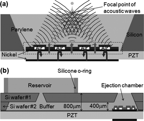
The ejector is integrated with an ejection chamber, a buffer and a microchannel, which are microfabricated with silicon wafers (). A silicone o-ring is used as a dam for the reservoir. Due to hydrostatic pressure and surface tension, all water in the reservoir can be delivered to the ejection chamber, where the liquid level is maintained at the top surface of the silicon chamber, as the liquid is ejected out by the ejector.
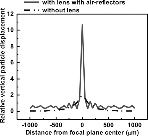
Since the droplet is ejected in the vertical direction and is most related to the vertical particle displacement, simulations are performed to visualize the focusing effect of the lens as shown in . The ejector without lens is also shown for comparison. The sharp increase of the vertical particle displacement at the focal point indicates that the acoustic wave is well focused into a narrow beam width at the center of the top liquid surface. The focused acoustic beam is 5.5 times stronger in intensity and 4 times narrower in full width at half maximum (FWHM) for the ejector with lens than without lens.
For aerosol production, small droplets are ideal for generating small particles, for quick airborne evaporation, and for reducing requirements for high purity solvents when generating tiny particles. The ejected droplet size is primarily determined by the diameter of the focused acoustic beam at the focal plane that is related to the acoustic wavelength in the liquid. The droplet size is thus inversely proportional to the frequency for acoustic ejection. In order to work at a higher frequency and still produce large acoustic power, the transducer can be excited with Q-enhancement from resonance at the nth harmonic frequencies,
TABLE 1 Detailed dimensions of the rings for different harmonic designs
In this study, the acoustic wavelength (∼ 75 μ m at 20 MHz; ∼ 11 μ m at 140 MHz) is much larger than the particle size (1 μ m), and the wave propagation in the suspension of particles occurs in the viscous regime (CitationKytomaa 1995). The most critical acoustic parameter for acoustic lens design is the acoustic velocity, to which the modification induced by the presence of particulates has to be taken into account. The predicted acoustic velocity using the effective medium approach has been shown to match experimental results very well (Reis et al. 2005). In the theory, the acoustic velocity of a suspension containing a volume fraction φ of particles is given by
3. FABRICATION AND TESTING SETUP
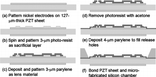
The PZT ejector and silicon microfluidic components were fabricated as described below, according to the processing steps illustrated in . The acoustic ejector was built on a 127-μ m-thick PZT sheet (PSI-5A4E, Piezo Systems, Cambridge, MA). On both sides of the PZT sheet, nickel electrodes were first patterned. Next, 3-μ m-thick photoresist was spun and patterned as the sacrificial layer. After depositing and patterning 3-μ m-thick parylene as the lens material, we removed the photoresist with acetone. Another 4-μ m-thick parylene was then deposited to fill the release holes.
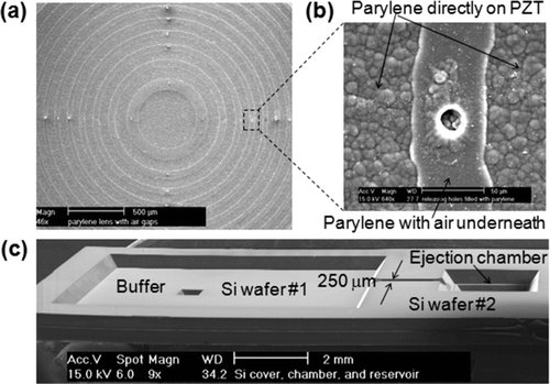
The microfluidic components (embedded microchannel, ejection chamber, and buffer) were microfabricated with two 400-μ m-thick silicon wafers. Both sides of the silicon wafers were first deposited with 0.8-μ m-thick SixNy by low-pressure chemical vapor deposition (LPCVD). The front-side SixNy was then patterned, followed by anisotropic etching of bulk silicon in KOH. The SixNy was removed, and two silicon wafers were bonded together with epoxy. Finally, the PZT sheet was adhesively bonded to the silicon wafers. shows the scanning electron microscope (SEM) photographs of the fabricated PZT acoustic ejector and the silicon microfluidic components.
FIG. 4 SEM photographs of the fabricated device. (a) The acoustic lens on PZT substrate. (b) The release hole being filled with parylene. (c) The microfabricated buffer, microchannel, and ejection chamber, before bonded with the PZT ejector (upside-down view).
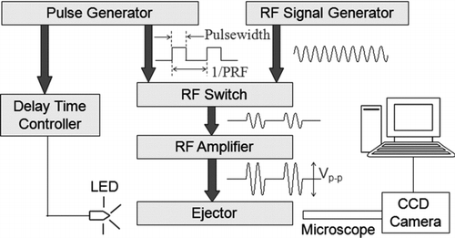
For the device testing, sinusoidal pulses were applied to the ejector to eject liquid droplets in a setup shown in . First, the sinusoidal signal was modulated with radio-frequency (RF) pulses through a high-speed switch. The pulse repetition frequency (PRF) used was ranging from 1 Hz to 10 kHz. The pulsed signal was then amplified with an RF power amplifier (A041, LCF Enterprises) and fed into the device. A glass substrate was placed above the device to collect the ejected droplets. A charge-coupled device (CCD) camera (SONY SSC-DC54A) with a microscope was placed horizontally to record the ejection process as we stroboscopically blinked a light-emitting diode (LED). Synchronization of the flash illumination with the sinusoidal pulse input was achieved by turning on the LED with another pulse source triggered by the pulse generator that pulsed the sinusoidal signal. By varying the delay time between the illumination of LED and the RF signal applied to the transducer, we observed the ejection process at any moment.
The particles used in testing the system were 1-μ m-diameter monodisperse PSL microspheres suspended in water (1% solids) (Duke Scientific Corporation, Palo Alto, CA). A surfactant was added to the mixture by the manufacturer to allow the PSL microspheres to be uniformly suspended. In the tests performed here, the 1% PSL suspension was used without dilution.
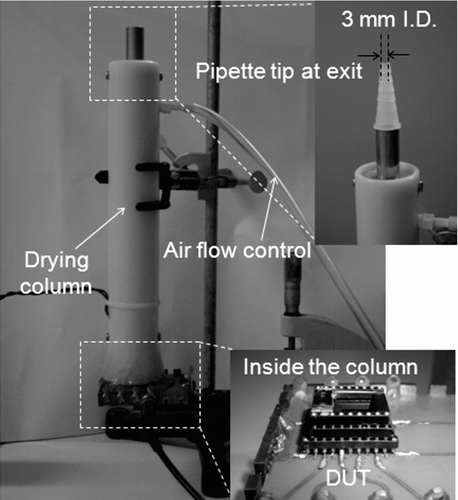
Generation of dry particles from droplets requires that the liquid from the droplets evaporate to leave behind the solid particle. To increase the rate of evaporation, for easier collection of the residual dried particles, we ejected the particle-containing droplets into a drying column that had been designed for an IJAG system (CitationBottiger and DeLuca 1999) (). The drying column is composed of an outer tube and an inner metal tube. The outer tube has an inner diameter of 37 mm while the inner tube has an inner diameter of 15 mm. They are 118 mm (outer tube) and 132 mm (inner tube) in length. The inner tube is shorter than the outer tube at the bottom end, and the ejector device footprint (17 mm × 15 mm) is small enough to fit into the drying column from the bottom. The drying column covered the device, which was packaged in a dual-in-line package (DIP) and mounted on a printed circuit board (PCB) with patterned RF microstrip lines. Silicone gel was used to provide an airtight seal between the drying column and the PCB so that we could pump air into the column (using a pump that went with the system) without an airtight box. The air flowed from the outer tube down, picked up the ejected droplets and flowed up inside the inner tube. The inner exit tube extended up 31 mm more than the outer tube, and a glass slide was placed near this exit tube for particle collection. After we applied actuation signals through the microstrip lines to eject droplets, we could dry the droplets inside the column by adjusting the air flow (from 0 to 3 L/min) and heat (from room temperature to 140°C). For our experiment, the particles were typically produced by acoustic ejection with a temperature setting of 78°C inside the inner metal tube, and a flow of 3 L/minute through the drying column. A thermocouple was used to confirm the temperature inside the inner metal tube. A small pipette tip (with an inner diameter of 3 mm) was placed on the exit to increase the collection efficiency by increasing the particle velocity and inertia as the particles move toward the slide. Because the acoustic ejector used is made to operate by ejecting droplets upward, the drying column is placed above the ejector, and droplets flow upward through the column, although the drying column had been designed for the droplets to be ejected downward into the column and to flow downward.
4. EXPERIMENTAL RESULTS
4.1. Ejection of Pure Water Droplets
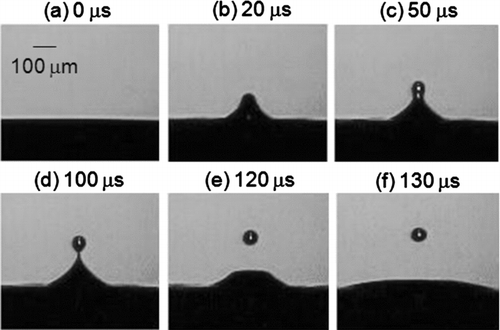
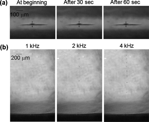
We first tested the fabricated ejector working at the fundamental resonant frequency, using D.I. water as the liquid medium. The ejector was driven with RF pulses of 20-MHz sinusoidal signals of ± 60 Vp-p (the peak electrical field across the PZT substrate being around 0.47 MV/m). The pulsewidth and the pulse energy were 7 μ s and 168 μ J, respectively. The time evolution of the droplet formation is shown in . After the actuation signal was applied (), the liquid was first mounting up (). The droplet was then formed () and broke free from the bulk liquid (, e). As the ejected droplet continued to travel, the liquid surface rapidly returned to its flatness (). The ejection is one droplet per pulse and free of satellite droplets. The ejected droplet has a diameter of around 80 μ m, very close to the acoustic wavelength at 20 MHz. As the liquid was ejected, water in the reservoir was automatically supplied to the ejection chamber. shows the continuous ejection at 60-Hz PRF, during which the RF frequency was fixed at 20 MHz without any fine tuning. Frames at different time are almost identical, exhibiting the uniformity of the droplet sizes and the stability of ejection process. shows ejections at higher ejection rates.
FIG. 8 (a) Optical photographs of stable and continuous acoustic ejections. (b) Optical photographs of droplet ejections at the ejection rates of 1, 2, and 4 kHz.
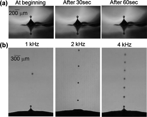
Next, we characterized the ejector working at the harmonics in order to get smaller droplets. shows the continuous ejection at 60-Hz PRF with RF pulses (± 70 Vp-p with 7-μ s pulsewidth) of 140-MHz sinusoidal signals based on the 7th harmonic operation. The ejected droplet size is only around 14 μ m in diameter. shows ejections at rates up to 4 kHz.
4.2. Ejection of Water Droplets Containing Polystyrene Microspheres
For the particle-generation application, the material used in this study is 1% 1-μ m monodisperse PSL microspheres in water. The PSL microspheres are uniformly suspended with the addition of surfactant, and the overall suspension has a density of around 1 g/cm3. For a volume fraction of 1%, the effect of particulates on acoustic velocity and hence the acoustic ejector design has been calculated to be negligible. The device working at the 7th harmonic was used for demonstration.
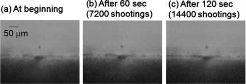
We first ejected the solution without using the drying column. Driven with RF pulses (± 70 Vp-p with 7-μ s pulsewidth) of 140-MHz sinusoidal signals, the acoustic ejector produced stable and continuous ejections of droplets containing particles. Because the particles account only for a 1% volume fraction of the suspension solution, the optimum electrical condition required for ejection is very similar to the condition for D.I. water. The droplet size is around 14 μ m in diameter (∼ 1.4pL). shows the ejections at 120-Hz PRF of 1-μ m PSL particles in 14-μ m droplets. The smallest cross section between the embedded reservoir and the ejector is 250× 400 μ m2, and the microspheres do not cause any clogging while the liquid and microspheres are continuously transferred from the reservoir to the ejector. The ejection of suspension is one droplet per pulse and free of satellite droplets.
FIG. 10 Optical photographs of stable and continuous ejections (at 120-Hz PRF) of 1-μ m polystyrene latex (PSL) particles in 14-μ m droplets.
For examining the distribution of the number of particles per droplet, we collected the droplets on a glass slide placed 3 mm above the device, and counted the particles under an optical microscope. shows the particles collected on the slide as the droplets hit the slide wet. Particles in each droplet were confined within the boundary formed by the liquid stain (). The circular region of contact between the flattened liquid droplet and the glass, after it is collected, is about 25 μ m in diameter. The droplet's position could be precisely controlled to form arrays ( illustrates a 2× 2 array), or to land at a same spot ( illustrates the stain left by the very large flattened droplet formed when about 100 droplets were rapidly deposited at one point).
FIG. 11 Optical photographs of particles in droplets collected on the slides as the droplets hit the slide wet. (a) Particles in one droplet. (b) A 2 × 2 array of particles in droplets. (c) Accumulation of ∼ 100 droplets at the same spot (particles were uniformly distributed inside the droplets and clustered around the circular edge).
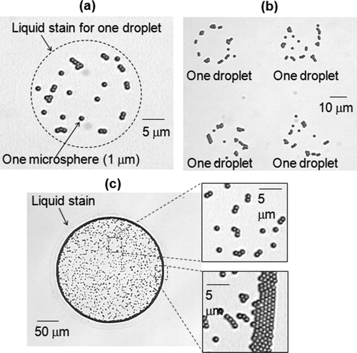
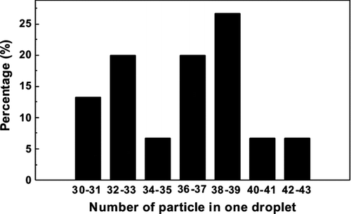
The distribution of the number of microspheres in each ejected droplet is illustrated in . For this distribution of droplets, the experimental average number of microspheres in each droplet is 36, and the standard deviation is 3.5. A 14-μ m-diameter (1.4-pL) droplet of a 1% solution should theoretically contain about 30 microspheres. For this characterization without the drying column, we do not see how we could have missed droplet stains from droplets containing small numbers of PSL spheres, because the ejection of suspension is one droplet per pulse and free of satellite droplets. There were no isolated spheres seen on the slide. We are not sure why we counted about 20% more particles than expected. However, a small inaccuracy in our droplet diameter can result in a larger error in the volume (e.g., a diameter of 15 μ m instead of 14 μ m results in a droplet with 23% more volume and particles). The droplet formation mechanism that we were employing is acoustic ejection. The acoustic waves are only focused into a narrow beam width at the center of the top liquid surface without major disturbance in the bulk liquid. If the PSL particles tend to reside at the surface of the liquid more than they are in the bulk, because the surfactant helps keep the PSL spheres in water but does not do that perfectly, then more PSL spheres may be in each ejected droplet than is calculated from the PSL-sphere concentration in the bulk liquid.
Because the average number of microspheres in each droplet is 36, and the standard deviation is 3.5, the variance to mean ratio is 3.52/36 = 0.34. If the spheres were distributed completely randomly in the bulk solution, one would expect a Poisson distribution, which has variance to mean ratio of 1.0. So, to the extent we can draw conclusions from this small sample, this is an example of sub-Poisson statistics. Because the spheres are hard, the centers of no two spheres can come closer together than 1 μ m, the spheres are more uniformly separated than point spheres would be, and so the distribution of the sample should be sub-Poisson. With 30 spheres inside a 1.4 pL droplet, the volume of water per sphere is 1.4 pL/30 = 0.047 pL, which is equivalent to a cube 3.6 μ m on a side, a length that is not particularly large compared to the 1 μ m sphere. Also, the surfactant should form a coat (hydrophilic on the outside), which keeps these hydrophobic spheres in solution. Typically the weight of the dry surfactant is larger than the weight of the PSL spheres. In this example where undiluted PSL spheres were used, it may be that the surfactant layer is thicker than it is in a diluted sample. The effective volume of the surfactant increases when it is hydrated.
4.3. Ejection of Water Droplets Containing Polystyrene Microspheres into a Drying Column
Generation of dried particles from liquid droplets that contain either small particles or non-volatile solutes requires that the carrier liquid evaporate. A drying column can be used to facilitate this drying (CitationBottiger and DeLuca 1999). Here we combined the acoustic ejector with the heating column from the IJAG as described in section 3 above. As the ejected droplets flow through the drying column, water evaporates and leaves behind the dry PSL particles. At 50% relative humidity, a stationary 14-μ m droplet evaporates in about 0.4 s at room temperature (CitationFerron and Soderholm 1990), and can evaporate more quickly if the droplet is moving relative to the gas (CitationZhu et al. 2002). The drying column raises the temperature, and can entrain the droplets in an airstream that carries the particles to the collection surface.
and show optical micrographs of the particles produced by acoustic ejection with a temperature setting of 78°C and a flow of 3 L/min through the drying column, and collected on a slide for 10 seconds for each image. A thermocouple was used to confirm the temperature inside the inner metal tube, where the ejected droplets flowed through before being collected on the slides, and there was no major temperature gradient observed. As a result, neither the natural convection nor the thermophoretic deposition should contribute to the loss of particles. In addition, at this temperature range, it is not possible that the water was boiled to introduce dispersal of the content of droplets. illustrates how the rate of particle generation appears to be uniform in time. The acoustic ejector stably ejected particles-in-droplets at 300-Hz PRF for more than 10 minutes (180,000 droplets ejections) until all liquid in the reservoir was ejected. There was no observable difference in particle concentration through time (at the beginning, after 5 minutes, or after 10 minutes).
FIG. 13 Optical photographs of particles collected on the slides (each slide collected ejected particles for 10 seconds) after the ejected droplets were dried in the drying column. Droplets were ejected continuously for more than 10 minutes without observable difference in particles concentration through time.

FIG. 14 Optical photographs of generated particles collected on the slides by different ejection rates (each sample collected ejected particles for 10 s).
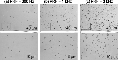
illustrates that the concentration of particles collected were found to be proportional to the droplet ejection rates for PRFs of 300 Hz, 1 kHz, and 3 kHz, as expected. Since a 14-μ m-diameter (1.4-pL) droplet of a 1% solution should theoretically contain about 30 microspheres, the theoretical particle generation rate (with droplets generated at 3 kHz) was around 90,000 1-μ m-diameter PSL microspheres/s. To experimentally characterize the generation rate, we examined the optical photographs of generated particles collected on the slides. We manually counted the number of particles collected within a 125 μ m × 175 μ m area on the slides, and calculated the corresponding density. Since each sample collected ejected particles for 10 seconds, the final density was divided by 10 seconds. We estimated the peak particle concentrations to be more than 50,000 microspheres/s•cm2 collected on the slide (). The area over which the particles were collected was around 1 cm in diameter. The particles were more concentrated in the center and loosely distributed in the outer areas, and the number cited in the previous sentence is for the center area. The distance between the slide and the column exit (of which the opening diameter was 3 mm) was between 1 and 2 mm. It is not possible to make a good estimate of the fraction of the ejected microspheres that were collected, but with the nozzle-to-slide spacing about half of the nozzle diameter, the region where the peak particle concentration occurs might be within about 0.5 cm. If that diameter were 0.5 cm, then the PSL particles collected on the slide would be 9,000/s when the PRF is 3 kHz, and the fraction of ejected particles that are collected would be about 10%.
TABLE 2 Comparisons among different ejection rates (the theoretical particle generation rate is based on 30 microspheres per droplet)
5. DISCUSSION
When the droplets were ejected into the drying column, and the dried PSL particles were collected on a slide, as in and , the collected particles appeared primarily as individual 1-μ m spheres, instead of agglomerates of the 1-μ m spheres (as is typical when the drying column is used with the IJAG or a nebulizer). This finding suggests the possibility of making an acoustic-ejector-drying-column combination that could generate either individual particles (as in the PSL spheres here), or agglomerates, by varying the airflows through the drying column.
The particle size of the agglomerate particle (of about 36 1-micron-diameter polystyrene particles) would be around 3 or 4 micrometers, and should reach this size well before it reaches the top of the drying column. The size of the ejected droplet is 14 microns in diameter, and decreases rapidly because of evaporation in the heated air. The air-flow velocity and temperature inside the drying column are 0.22 m/s and 78°C, respectively, while the drying-column length and initial droplet velocity are 132 mm and 2 m/s, respectively. The time the ejected droplet spends in the drying column is estimated to be less than 5 s (the column length divided by the air velocity) because the settling velocity for a 15-micrometer-diameter water droplet is about 0.68 cm/s, which is about 32 times smaller than the air flow rate. The water in the droplet is expected to have evaporated in the 78°C column by the time the droplet reaches the column top, largely because that column has been used extensively to dry 40–50 micrometer-diameter water droplets ejected by an ink-jet.
We do not know why the 1-μm particles in and do not appear as agglomerates of 1-μ m-diameter spheres, with about 30 or 36 spheres per agglomerate, although we have ruled out some explanations and left others as possibilities.
| 1. | One suggested explanation is that the droplets might be ejected with a net charge, and when they evaporate down to the Rayleigh limit for charge (CitationDavis and Schwieger 2002; CitationSmith et al. 2002), they explode into smaller droplets containing few PSL spheres, and the process is repeated until individual PSL spheres are the result. However, we have checked this and ruled out the possibility. Unlike the high voltage (in kilovolts range) typically used for electrospray process, the voltage we used for acoustic ejection is only around 60–70 V. Also the capillary dimension used for electrospray is much smaller than our ejection chamber (since the acoustic ejection happens in an open space without any nozzle). In addition, we have experimentally checked that there was insufficient charge on the droplets. We ejected droplets of (a) D.I. water and (b) D.I. water containing particles in two sets of experiments—one without electrical field and the other with an electrical field high enough to cause deflection on the trajectory of the ejected droplets (if charged). The ejector was placed between two parallel metal plates. The distance between the two plates was 3 mm and the voltage applied was 50 V (the applied electric field was 16.7 kV/m). Since our droplets were ejected with an initial velocity around 2 m/s, an acceleration velocity (from the electric field perpendicular to the ejection velocity direction) in the range of 1 m/s2 should be more than enough for a noticeable trajectory change. Very conservatively assuming that only one elementary charge would be induced for every 1012 dalton water molecules, an electric filed of 16.7 kV/m would yield an acceleration velocity of around 1.6 m/s2, according to Newton's laws of motion. However, we observed no effect of the electrical field on the trajectory or the velocity of the ejected droplet (i.e., D.I. with and without electric field or D.I. containing particles with and without electric field, all exhibit very similar traveling trajectory), confirming that the droplets were not charged. | ||||
| 2. | Turbulence may be generated near the ejector, where the heated air moves from the outer concentric cylinder into the inner concentric cylinder of the drying column. Possibly this turbulent airflow might affect the surface of the liquid as the droplets are being ejected and somehow affect droplet generation. We have never noticed such an effect, and would not expect a large air velocity at the liquid surface. If the airflow at the surface did distort the ejection process, then a differently designed drying column, where there is negligible airflow at the liquid surface, could circumvent this problem. | ||||
| 3. | Another possibility is that turbulence is generated in the air as it moves into the inner cylinder, and this turbulent flow causes many of the droplets to impact on the wall of the metal cylinder, which causes the droplet to break into one or more larger droplets which stick to the wall, and smaller droplets which are carried more readily in the flow. These small droplets resulting from the droplet breakup happen to be small enough to usually only carry one PSL sphere, and are more readily carried upward and out the nozzle. Although the high surface tension of water and the small size of the droplets (14-μ m) argue against this possibility, the droplets ejected include a surfactant in sufficient concentration to stabilize the PSL. Some surfactants can reduce the surface tension of water to about 1/3 of the DI value. Any evaporation would increase the surfactant concentration. The high temperature (78°C) would lower the surface tension of DI water from about 70 dynes/cm at 20°C to about 61 dynes/cm (not such a large decrease). Also, the metal tube should be 78°C also if the air is 78°C. Metal is relatively hydrophobic. If turbulent airflow drives the droplets toward the surface we might estimate that they could be moving as fast as 1 m/s. They probably tend to impact at a high angle from the normal to the surface. | ||||
| 4. | Another suggested explanation is that the airflow at the column exit is turbulent enough to influence the particle collection and distribution over the slide. This possibility seems unlikely because the velocity of the air (3 L/minute) exiting through a 3-mm nozzle is not large compared with velocities used in collecting agglomerated particles in other applications. | ||||
Because of the PSL density and the surfactant added by the manufacturer of the PSL, the particles investigated in this study were uniformly suspended in the liquid before ejection. For other particles with higher or lower density, the acoustic ejector can be advantageously run in a mixing mode (140 ± 10 MHz, ± 70 Vp-p, 4-μ s pulsewidth, and 1-kHz PRF) for several hundred msec before ejection (CitationYu et al. 2006).
6. CONCLUSION
A new method to produce airborne particles through acoustic ejection of droplets-containing-particles has been demonstrated. This acoustic ejector focuses acoustic energy at the liquid surface, and ejects uniform droplets without any orifice. Excited with RF pulses of 140 MHz (corresponding to the 7th harmonic thickness-mode resonant frequency), the ejector is shown to produce stable and continuous ejection of 14-μ m droplets containing 1-μ m PSL particles without any clogging. By varying the droplet ejection rates, we have been able to eject PSL microspheres at various rates up to 90,000 PSL particle/s (3,000 droplet/s). This efficient droplet-on-demand acoustic ejector proves to be an alternative to current ink-jet aerosol generators, particularly when orifice clogging is an issue.
Acknowledgments
This material is based upon work supported by the National Science Foundation (NSF) under Grant No. ECS-0310622.
REFERENCES
- Bottiger , J. R. , Deluca , P. J. , Stuebing , E. W. and Vanreenen , D. R. 1998 . An Ink Jet Aerosol Generator . J. Aerosol Sci. , 29 : S965 – S966 .
- Bottiger , J. R. and DeLuca , P. J. 1999 . Low Concentration Aerosol Generator United States Patent No. 5,918,254
- Davis , E. J. and Schwieger , G. 2002 . The Airborne Microparticle: Its Physics, Chemistry, Optics and Transport Phenomena , 289 – 290 . Springer .
- Davitt , K. , Song , Y.-K , Patterson , I II. W. R. , Nurmikko , A. V. , Gherasimova , M. , Han , J. , Pan , Y.-L and Chang , R. K. 2005 . 290 and 340 nm UV LED Arrays for Fluorescence Detection from Single Airborne Particles . Opt. Express. , 13 : 9548 – 9555 .
- Dougherty , G. M. , Hadley , D. R. , , O'Connor , P. R. and Bottiger , J. R. 2007 . Engineered Aerosol Production for Laboratory Scale Chemical/Biological Test and Evaluation Final Report, UCRL-TR-230829, DTRA–JSTO Project CA06TAS446, available online at https://library-ext.llnl.gov/
- Elrod , S. A. , Hadimioglu , B. , , Khuri-Yakub , B. T. , Rawson , E. G. , Richley , E. , Quate , C. F. , Mansour , N. N. and Lundgren , T. S. 1989 . Nozzleless Droplet Formation with Focused Acoustic Beams . J. Appl. Phys. , 65 : 3441 – 3447 .
- Eversole , J. D. , Hardgrove , J. J. , , Cary , W. K. Jr. , Choulas , D. P. and Seaver , M. 1999 . Continuous, Rapid Biological Aerosol Detection with the Use of UV Fluorescence: Outdoor Test Results. . Field Analytical Chemistry and Technology , 3 : 249 – 259 .
- Ferron , G. A. and Soderholm , S. C. 1990 . Estimation of the Times for Evaporation of Pure Water Droplets and for Stabilization of Salt Solution Particles . J. Aerosol Sci. , 21 : 415 – 429 .
- Fuller , S. B. , Wilhelm , E. J. and Jacobson , J. M. 2002 . Ink-Jet Printed Nanoparticle Microelectromechanical Systems . J. Microelectromech. Syst. , 11 : 54 – 60 .
- Hebner , T. R. , Wu , C. C. , Marcy , D. , Lu , M. L. and Sturm , J. 1998 . Ink-Jet Printing of Doped Polymers for Organic Light Emitting Devices . Appl. Phys. Lett. , 72 : 519 – 521 .
- Huang , D. and Kim , E. S. 2001 . Micromachined Acoustic-Wave Liquid Ejector . J. Microelectromech. Syst. , 10 : 442 – 449 .
- Hybl , J. D. , Tysk , S. M. , Berry , S. R. and Jordan , M. P. 2006 . Laser-Induced Fluorescence-Cued, Laser-Induced Breakdown Spectroscopy Biological-Agent Detection. . Appl. Opt. , 45 : 8806 – 8814 .
- Kytomaa , H. K. 1995 . Theory of Sound Propagation in Suspensions: A Guide to Particle Size and Concentration Characterization . Power Technol. , 82 : 115 – 121 .
- Lausted , C. , Dahl , T. , Warren , C. , King , K. , Smith , K. , Johnson , M. , Saleem , R. , Aitchison , J. , Hood , L. and Lasky , S. R. 2004 . POSaM: A Fast, Flexible, Open-Source, Inkjet Oligonucleotide Synthesizer, and Microarrayer . Genome Biol. , 5 : R58
- Lee , C.-Y , Yu , H. and Kim , E. S. 2006 . Nanoliter Droplet Coalescence in Air by Directional Acoustic Ejection . Appl. Phys. Lett. , 89 : 223902
- Lee , C.-Y , Yu , H. and Kim , E. S. 2007 . “ Harmonic Operation of Acoustic Transducer for Droplet Ejection Application ” . In Transducers ‘07, IEEE International Conference on Solid-State Sensors and Actuators , 1283 – 1286 . France : Lyon .
- Noble , C. A. and Prather , K. A. 2000 . Real-Time Single Particle Mass Spectrometry: A Historical Review of a Quarter Century of the Chemical Analysis of Aerosols . Mass Spectrometry Review , 19 : 248 – 274 .
- Pan , Y.-L , Hartings , J. , Pinnick , R. G. , Hill , S. C. , Halverson , J. and Chang , R. K. 2003 . Single-Particle Fluorescence Spectrometer for Ambient Aerosols . Aerosol Sci. Tech. , 37 : 628 – 639 .
- Pan , Y. L. , Pinnick , R. G. , Hill , S. C. , Rosen , J. M. and Chang , R. K. 2007 . Single-Particle Laser Induced-Fluorescence Spectra of Biological and Other Organic-Carbon Aerosols in the Atmosphere: Measurements at New Haven, Connecticut, and Las Cruces, New Mexico. . Journal of Geophysical Research-Atmospheres , 112 : D24519 doi:10.1029/2007JD008741
- Reis , N. , Ainsley , C. and Derby , B. 2005a . Ink-Jet Delivery of Particle Suspensions by Piezoelectric Droplet Ejectors . J. Appl. Phys. , 97 : 094903
- Reis , N. , Ainsley , C. and Derby , B. 2005b . Viscosity and Acoustic Behavior of Ceramic Suspensions Optimized for Phase-Change Ink-Jet Printing . J. Am. Ceram. Soc. , 88 : 802 – 808 .
- Schafer , J. , Mondia , J. P. , Sharma , R. , Lu , Z. H. and Wang , L. J. 2007 . Modular Microdrop Generator . Rev. Sci. Instrum. , 78 : 066102
- Smith , J. N. , Flagan , R. C. and Beauchamp , J. L. 2002 . Droplet Evaporation and Discharge Dynamics in Electrospray Ionization . J. Phys. Chem. A. , 106 : 9957 – 9967 .
- Song , Y. L. , Tsai , S. C. , Chen , C. Y. , Tseng , T. K. , Tsai , C. S. , Chen , J. W. and Yao , Y. D. 2004 . Ultrasonic Spray Pyrolysis for Synthesis of Spherical Zirconia Particles . J. Am. Ceram. Soc. , 87 : 1864 – 1871 .
- Yu , H. , Kwon , J. W. and Kim , E. S. 2006 . Microfluidic Mixer and Transporter Based on PZT Self-Focusing Acoustic Transducers . J. Microelectromech. Syst. , 15 : 1015 – 1024 .
- Zhu , J. , Zheng , F. , Laucks , M. L. and Davis , E. J. 2002 . Mass Transfer from an Oscillating Microsphere . J. Colloid and Interface Sci. , 249 : 351 – 358 .
