Abstract
Insect screens, which are usually an integral component of an air sampling inlet, can cause inadvertent deposition of larger aerosol particles. Numerical and experimental studies were performed to characterize aerosol deposition on commercially available electroformed wire screens for aerodynamic particle diameters between 3 and 20 μ m, Stokes numbers between 0.49 and 20, wire widths between 35 and 160 μ m, and screen open area fractions of 0.56 to 0.90. With increasing values of Stokes numbers, the actual collection efficiency increases gradually to a maximum value that is asymptotic to the fraction of open area. Deposition is characterized in terms of a standardized screen efficiency, which is the actual efficiency divided by the areal solidarity (1–fraction of open area). A correlation equation has been developed for the electroformed mesh screens, which relates the standardized efficiency to the fraction of open area, the Stokes number, the interception parameter, and the Reynolds number based on wire size. Data obtained from experimental studies with two screen types and numerical studies with those, plus two additional screen types, over a wide range of Stokes numbers and wire Reynolds number (Re w ) from about 0.5 to 30, collapse to a single correlation curve, which is valid for the range of variables tested. The pressure drop across the screens is low, on the order of 1 Pa for face velocity values that are on the order of 1 m/s. A regression analysis was used to obtain coefficients that fit the results of the numerical experiments to an existing pressure loss model.
SYMBOLS AND ABBREVIATIONS
| AF | = |
After-filter |
| cf | = |
Concentration of fluorescein in filter or screen sample |
| C | = |
Aerosol concentration |
| Cc | = |
Cunningham's slip correction |
| CP | = |
Pressure coefficient |
| CAF | = |
Aerosol concentration calculated from material collected on after-filter |
| CSM | = |
Aerosol concentration calculated from material collected on screen |
| dw | = |
Wire width |
| D | = |
Diameter of transport tube screen in experimental test setup. |
| Dp | = |
Particle diameter |
| f 1, f 2 | = |
Intermediate functions used in modeling |
| Dm | = |
Diameter of the droplets measured under the microscope |
|
| = |
Drag force per unit mass |
| fOA | = |
Fraction of open area of a screen |
|
| = |
Gravitational acceleration |
| G | = |
Parameter used in pressure coefficient correlation |
| h | = |
Height or width of the computational domain |
| n | = |
number of data points in a statistical sample |
| Q | = |
Air volumetric flow rate |
| R | = |
Interception parameter =Dp /dw |
| R 2 | = |
Statistical coefficient of determination for a correlation |
| Re | = |
Reynolds number base on superficial velocity |
| Re w | = |
Wire Reynolds number base on average velocity in screen openings |
| SM | = |
Screen mesh |
| s g,y | = |
Standard error expressed as a geometric standard deviation |
| Stk | = |
Stokes number |
| Stk 50 | = |
Stokes number for which the standardized collection efficiency is 50% |
| t | = |
Time |
|
| = |
Particle velocity |
| U | = |
Average air velocity in the openings of a screen |
| Uo | = |
Face (superficial) velocity |
| V | = |
Volume of solution used to elute the tracer |
| WL | = |
Wall loss in duct between screen location and filter location |
|
| = |
Particle position |
| ΔP | = |
Pressure drop across a screen |
| η A | = |
Actual efficiency |
| η SS | = |
Standardized screen efficiency |
| μ | = |
Air dynamic viscosity |
| ν | = |
Air kinematic viscosity |
| ρ a | = |
Air density |
| ρ p | = |
Particle density |
INTRODUCTION
Wire screens are extensively used in a variety of industries for size classification of powders, product separation, impurity removal, particle filtration, and mist elimination (CitationCapps 1994). In ambient aerosol sampling, screens are used to strip unwanted large-sized debris such as insects, plant debris, and fibers. An effective screen in air sampling applications is one that collects the unwanted debris while allowing aerosol particles of interest to penetrate with minimum deposition. Generally woven wire screens are used in air sampling, which have mesh sizes of about 16 × 16, where the mesh size is the openings per linear inch.
The penetration of aerosol particles through fibrous filters has been widely studied from theoretical and experimental points of view (CitationLee and Liu 1982; CitationLiu and Pui 1975; CitationSuneja and Lee 1974). However, studies of aerosol penetration through screens have largely been confined to the nano-particle regime with an emphasis on the size separation of these particles in diffusion batteries that consist of a series of screens (CitationScheibel and Postendorfer 1984; CitationCheng et al. 1990, CitationCheng 1993; CitationAlonso et al. 2001). There is little information available on the penetration of aerosol particles in the size range of interest for ambient air sampling inlets, which is generally comprised of sizes less than about 20 μm aerodynamic diameter (AD).
In a screen, as in a fibrous filter, as air flows through the system particle trajectories may deviate from the air streamlines due to Brownian motion, interception, inertial impaction, and gravitational settling. For a particular screen configuration, flow conditions and particle size usually determine the mechanisms that govern deposition. The penetration process is strongly influenced by fraction of open area (fOA , also known as the areal porosity) and the Stokes number Stk. The important deposition mechanisms for particles in the range of interest (1 to 20 μm AD) could be considered to be interception, inertia impaction and gravitational settling. Other forces, such as electrostatic forces and diffusion, are ignored in this study. Particle rebound from the screen wires was not considered. In numerical simulations we assumed that if a particle struck a screen wire it would remain attached to the wire, and in the experimental testing we used liquid droplets for which we also assumed an attachment coefficient of unity. For air sampling screens, where it is desired to have low deposition on screen wires of aerosol particles with sizes less than 20 μm AD, the assumption of an attachment coefficient of unity provides conservative estimates of sample transmission.
Herein we chose to evaluate the performance of electroformed (aka electromesh) screens () because their geometry, which has very uniform openings, lends itself better to analysis than does that of woven wire screens. The principal objective of the present research was to study aerosol deposition on these screens through experimental and numerical techniques, as a means of developing models that will allow prediction of the collection efficiency as a function of design and operational variables. In continuing work, we are studying the application of these models to woven wire screens. The electromesh screens are not available with openings as large as those of woven wires that are typically used in the air sampling inlet applications (e.g., 16 × 16 mesh), but the protocol used to develop models based on experiment and simulations, is helpful in work with woven wire screens. The tolerances of opening sizes for electroformed mesh screens used in this study (InterNet Inc., Anoka, MN) are specified by the American Society of Testing and Materials (CitationASTM 2004). Regardless of opening size, the allowable tolerance is ±2 μm.
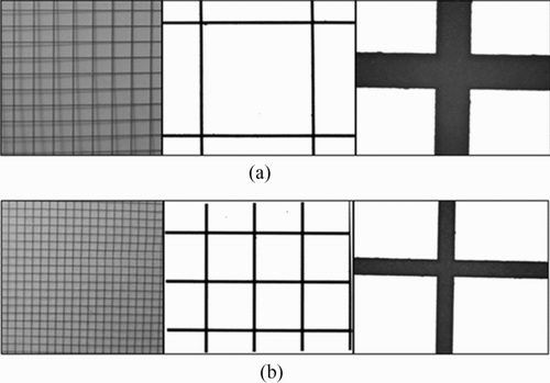
FIG. 1 Photographs of electroformed wire screens that were experimentally tested for aerosol deposition characteristics. (a) Screen A of , 20 mesh with a wire width of 65 μm. (b) Screen B of , 45 mesh with a wire width of 35 μm.
An experimental investigation of aerosol collection on two commercially available electroformed screens was performed over a wide range of operational conditions. Three-dimensional Computational Fluid Dynamics (CFD) simulations of the performance of these two screens were undertaken and the numerical predictions were compared with the experimental results, which verified the veracity of the numerical simulations. Simulations were extended to two other screens that were not experimentally tested. Empirical correlations for aerosol deposition on electroformed screens are developed and a single correlation is presented that allows determination of collection efficiency as a function of design and operational variables.
PARAMETERS
The parameters of interest for the screens shown in are the mesh size (number of openings per linear inch), wire size (dw ), and the fraction of open area (fOA ). Because the wires of an electroformed mesh are approximately rectangular in cross section with rounded corners, they were approximated by cylinders with a diameter equal to the wire width. presents a summary of the important features of the four different commercially available electroformed screens that were used in the study.
TABLE 1 Commercially available electroformed screens used in study.
As air flows around the wires, particles may impact on them. The impaction process is governed by the Stokes number (Stk), the fraction open area, and the wire Reynolds number, Re w , which is calculated based on the velocity, U, in the screen, where:
EXPERIMENTAL STUDIES
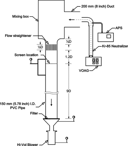
shows a schematic diagram of the system used to experimentally measure aerosol penetration through the screens. It employs a vibrating orifice aerosol generator (VOAG, Model 3450, TSI Inc., St. Paul, MN), a 10 mCi Kr-85 neutralizer, a vertical tube (147 mm diameter), an aerodynamic particle sizer (APS, Model 3321, TSI Inc., St. Paul, MN), an after-filter, and a Hi-Vol blower (Model GBM2360, ThermoAndersen, Smyrna, GA). The Hi-Vol blower was calibrated through use of a Roots meter (Model 5M 125 TC, Dresser Measurement, Houston, TX), a flow meter (HFC-digital-1400, Hi-Q Env. Products, San Diego, CA), and U-tube or digital manometer (Model 8360, TSI Inc., St. Paul, MN).
The test procedure consisted of first bringing the aerosol generator to a steady operating condition, and then measuring the particle size output from the VOAG. The electrically neutralized aerosol was passed through a 203 mm (8.0 inches) duct and into an aerosol mixing box (CitationHan et al. 2005), which was used to create a uniform aerosol concentration at the entrance of a vertical flow tube. A flow straightener was placed in the vertical tube to eliminate large scale turbulence and flow swirl generated by the mixing box. The vertical tube was 147 mm (5.78 inches) diameter and had provisions for mounting a test screen and a glass fiber after-filter. The test screen location was 1.2 tube diameters below the flow straightener, and the after-filter was mounted 9 duct diameters downstream of the screen. The system was operated with a glass fiber after-filter (AF) in place to collect the particles that passed through the screen.
The aerosol particles were liquid droplets of oleic acid tagged with a fluorescent tracer, sodium fluorescein. For analysis, a solution of 2/3 isopropyl alcohol and 1/3 distilled water was used to elute the sodium fluorescein tag from each exposed after-filter and to wash collected tracer from the screen. Aliquots of the solutions (4 mL) were analyzed with a fluorometer (Model 450, Sequoia-Turner Corp., Mountain View, CA). One drop of sodium hydroxide (1N NaOH) was added to each 4 mL aliquot prior to analysis. The aerosol concentration, C, is calculated from analysis of a liquid sample by:
NUMERICAL STUDIES
Three-dimensional numerical simulations were performed using the CFD software, Fluent (Version 6.1.22, Fluent Inc., Lebanon, NH, US). Deposition of the aerosol particles on the screen was modeled as a dilute two-phase flow problem under the Eulerian-Lagrangian framework, with an assumed one-way coupling between the phases (air flow affects particle motion but not vice versa). A convergent flow field was obtained on the domain of interest, then aerosol particles were released at appropriate locations and their trajectories computed as a post-processing operation to determine deposition on the screen. Numerical predictions of deposition were then compared to the experimental results.
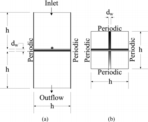
shows a computational domain used in the simulations together with appropriate boundary conditions. A channel of the computational model was isolated for analysis purposes by employing periodic boundary conditions at the interfaces with the neighboring channels. The computational domain for the simulations was constructed from the nominal geometric values for the screen. Electromesh screens have all wires in a plane; however, we conducted the detailed numerical analyses with the layered wire arrangement shown in . The reason was that we wished to use a common numerical method for analyzing both the electromesh screens reported herein and woven wire screens, which is to be reported later. Sample simulations compared with experimental results showed the layered arrangement worked well for both the electromesh and woven wire screens. Also, nearly the same results were obtained with Screen A () whether the wires were in-plane or layered (Han 1007). A uniform, normal velocity profile was specified at the inlet boundary. Mass outflow boundary conditions were imposed to model the flow exit. A no-slip boundary condition was imposed on all wall surfaces in the computational grid. A block-structured body-fitted coordinate system with a structured hexagonal grid was used for the discretization of the simulation domain. The number of computational cells varied from 1,800,000 to 2,100,000 depending on the screen configuration. Convergence was declared when the values of the normalized residuals for the continuity and momentum equations were less than 1×10⁻⁵.
FIG. 3 Schematic of computational domain used in modeling deposition of aerosol particles on screen wires. (a) Side view. (b) Top view.
After solving transport equations for the continuous phase, the particle velocities were calculated from time integration of:
TABLE 2 Range of numerical and experimental test parameters for the test screens
RESULTS AND DISCUSSION
Aerosol Particle Collection Efficiency
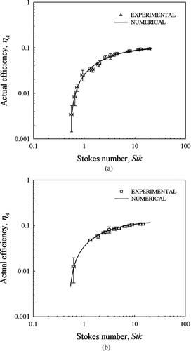
A comparison of the experimentally determined collection efficiency values with the numerical predictions is given in and for screen types A (20 × 20 mesh) and B (45 × 45 mesh) of . An initial comparison of numerical and experimental results showed that the experimental efficiency was somewhat higher than the numerical predictions, which was particularly apparent for Stokes numbers less than about unity where the slope of the curve is steep, and where use of the logarithmic ordinates of and exacerbates the effect of small arithmetic differences. To rationalize the difference, we recalculated numerical results with different software (CFX ver. 11, ANSYS, Canonsburg, PA) and a broader range of numerical parameters (mesh size, etc.), and we reviewed experimental measurements. The numerical results did not change sufficiently to account for the difference. We then took into account the small degree of heterogeneity in the aerosol produced by a vibrating jet (CitationHaglund et al., 2002) and obtained the correspondence between experiments and simulations that is shown in and . The heterogeneity of the aerosol is primarily due to the presence in the aerosol size distribution of multiplet droplets (droplets formed when two or more primary droplets collide and coalesce). However, as will be shown below, the correlation for predicting the efficiency of a screen is based on regression curves of a standardized efficiency fit to a combination of the experimental and numerical results, and not through direct use of the curve fits in . The standard error for the experimental data relative to the standardized efficiency curve is also discussed below.
FIG. 4 Collection of aerosol particles on screens: comparison of numerical predictions with results of physical experiments. (a) 20 × 20 mesh. (b) 45 × 45 mesh.
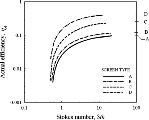
presents the numerical predictions for all four screen types, where the trends indicate that the efficiencies tend towards small values at a cutoff Stokes number of about 0.5, while for large values of the Stokes number, the efficiency curves tend to asymptotically approach the value of (1 – fOA ). Effect of gravity in the simulations on the efficiency predictions was investigated for larger particles sizes (11 and 20 μm diameter) and at superficial velocities of 0.11 m/s to 0.29 m/s (conditions that might be favorable for gravitational deposition) on screen types A and D. Results showed gravity has little effect for these simulated test conditions.
FIG. 5 Numerically predicted efficiencies for four electroformed wire screens, the details of which are given in . On the right-hand scale, the asymptotic values of the curves (1-fOA ) are 0.10, 0.12, 0.25, and 0.44 for Screen Types A, B, C, and D, respectively.
The observation that the numerically predicted actual efficiency values, η A , are asymptotic to (1 − fOA ), which is also consistent with analytical modeling of high inertia point particles, suggests that a new parameter, a “standardized efficiency” (η SS ) could be used to collapse the aerosol deposition data for different screens to a single performance curve. Here, we define the standardized screen efficiency as:
shows the correlation curve based on Equation (Equation13) together with the data points upon which the curve is based. The value of R 2 for these data points and Equation (Equation13) is 0.981 with a standard error of 0.026. If only the 31 experimental data points are compared with predicted values from Equation (Equation13), the value of R 2 is 0.935 and the standard error is 0.06.
Standard Error Based on Log Statistics
Because the standardized efficiency values associated with the range of independent variables span about 11/2 decades, it is appropriate to consider the standard error from the perspective of logarithmic statistics. The standard error, ln s g,y , expressed as a geometric standard deviation between the physical measurements and the regression curve, is:
For the 31 experimental measurements, in , the standard error, i.e., geometric standard deviation, in Equation (Equation14) is 1.18. This implies that if a value of the standardized efficiency is calculated to be 10%, then ±2 geometric standard deviations about the 10% value would cover a range from 7.2% to 13.9%, i.e., from 10%/1.182 to 10% × 1.182. This result is based on the particles size being associated with the size of the primary droplet produced by the VOAG and does not include a correction for the multiplets.
PRESSURE DROP
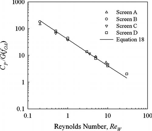
For design purposes, users of screens may need information on the pressure drop. Although the pressure loss is low, with values on the order of 1 Pa for face velocities, Uo , that are typical of those used in air sampling inlets (on the order of 1 m/s), we numerically modeled the pressure losses to provide results that can be used for estimation purposes. The pressure coefficient is defined as:
FIG. 7 Pressure coefficient, CP /G, as a function of wire Reynolds number for electroformed wire screens. The parameter values for the screens are given in . Symbols are numerical data and the solid lines are plots of the correlation, Equation (Equation18).
CONCLUSIONS
Physical experiments were conducted with commercially available electroformed wire screens to characterize the deposition of aerosol particles in a size range of interest for aerosol sampling inlets (<20 μm AD). In parallel, three-dimensional numerical simulations were performed to assess the utility of computational fluid dynamics as a tool for predicting deposition. The simulations of actual aerosol particle collection efficiency were in good agreement with experimental results over a wide range of Stokes numbers (0.49 to 20), screen fraction of open area (0.56 to 0.9) and wire Reynolds numbers (0.5 < Re w <30). The comparison of experimental and numerical results initially showed a small systematic difference, which was eliminated by correcting for the presence of multiplet droplets. As a result, it appears that in this study where the flow is laminar, the numerical results were better than typically reported experimental results, where the presence of multiplets is not taken into account.
A correlation was developed using the data base generated from the simulations to create a curve fit of the standardized efficiency, η SS , as a function of Stokes number, Reynolds number and interception parameter. Here, the standardized efficiency is the actual collection efficiency divided by the screen areal solidity expressed as (1 – fOA ). The standardized efficiency was selected because the actual efficiency is asymptotic, for high-inertia point particles, to (1 – fOA ). For the electroformed screens, which have mesh sizes from 20 to 50, a single correlation curve fit all of the results from the simulations and experiments.
The pressure drop across screens was also characterized with numerical simulations to establish a data base that would allow prediction of correlations of the pressure coefficient as a function of the wire Reynolds number (Re w ) and the fraction of open area (fOA ). The numerical results were used to fit coefficients in the model of CitationWakeland and Keolian (2003). The fit of the numerical results to the Wakeland and Keolian curve provided a value of R 2 of 0.991 over the range of wire Reynolds numbers from 0.2 to 30 and open area fractions from 0.56 to 0.9.
Funding was provided by the Aerosol Technology Laboratory of the Texas Engineering Experimental Station (TEES) and by the U.S. Army Research, Development and Engineering Command under Contract DAAD13-03-C-0050. We wish to thank Drs. Jerold R. Bottiger and Edward S. Stuebing, who are the technical managers of the contract. Computational time for the simulations was provided by the Texas A&M University Supercomputing Facility.
REFERENCES
- ASTM . 2004 . Standard Specification for Precision Electroformed Sieves. , ASTM Standard E-161-00. 14.02. American Society for Testing Materials, Philadelphia, PA
- Alonso , M. , Alguacil , F. J. and Nomura , T. 2001 . Turbulent Deposition of Aerosol Nanoparticles on a Wire Screen . J. Aerosol Sci. , 32 : 1359 – 1367 .
- Capps , R. W. 1994 . Properly Specify Wire-Mesh Mist Eliminators . Chem. Eng. Prog. , 90 : 429 – 433 .
- Cheng , Y. S. 1993 . “ Condensation Detection and Diffusion Size Separation Techniques ” . In Aerosol Measurement. , Edited by: Willeke , K. and Baron , P.A. New York : Van Nostrand Reinhold .
- Cheng , Y. S. , Yeh , H. C. and Yamada , Y. 1990 . Diffusion Deposition in Model Fibrous Filters with Intermediate Porosity . Aerosol Sci. Technol. , 12 : 286 – 299 .
- Haglund , J. S. , Chandra , S. and McFarland , A. R. 2002 . Evaluation of a High Volume Aerosol Concentrator . Aerosol Sci. Technol. , 36 : 690 – 696 .
- Han , T. 2007 . Experimental and Numerical Studies of Aerosol Penetration through Screens. , College Station, TX : Dept of Mech Eng, Texas A&M University . Ph.D. Dissertation
- Han , T. , O'Neal , D. , McFarland , A. R. , Haglund , J. S. and Ortiz , C. A. 2005 . Evaluation of Mixing Elements in an L-Shaped Configuration for Application to Single Point Aerosol Sampling in Ducts . Int. J. Heating, Ventilating, Air-Conditioning and Refrigeration Research , 11 : 657 – 672 .
- Hinds , W. C. 1999 . Aerosol Technology, , 2nd , New York : Wiley Interscience .
- Kline , S. J. and McClintock , F. A. 1953 . Describing Uncertainties in Single Sample Experiments . Mech. Eng. , 75 ( 1 ) : 3 – 8 .
- Lee , K. W. and Liu , B. Y.H. 1982 . Experimental Study of Aerosol Filtration by Fibrous Filters . Aerosol Sci. Technol. , 1 : 35 – 46 .
- Liu , B. Y. H. and Agarwal , J. K. 1974 . Experimental Observation of Aerosol Deposition in Turbulent Flow . J. Aerosol Sci. , 5 : 145 – 155 .
- Liu , B. Y. H. and Pui , D. Y. H. 1975 . Efficiency of Membrane and Nuclepore Filters for Submicrometer Aerosols . Environ. Sci. Technol. , 10 : 345 – 350 .
- Olan-Figueroa , E. , McFarland , A. R. and Ortiz , C. A. 1982 . Flattening Coefficients for DOP and Oleic-Acid Droplets Deposited on Treated Glass Slides . Am. Ind. Hyg. Assoc. J. , 43 : 395 – 399 .
- Scheibel , H. G. and Porstendorfer , J. 1984 . Penetration Measurements for Tube and Screen-Type Diffusion Batteries in the Ultrafine Particle Size Range . J. Aerosol Sci. , 15 : 673 – 687 .
- Suneja , S. K. and Lee , C. H. 1974 . Aerosol Filtration by Fibrous Filters at Intermediate Reynolds Number . Atmos. Environ. , 8 : 1081 – 1094 .
- Wakeland , R. S. and Keolian , R. M. 2003 . Measurements of Resistance of Individual Square-Mesh Screens to Oscillating Flow at Low and Intermediate Reynolds Numbers . J. Fluids Eng. , 125 : 851 – 862 .
![FIG. 6 Correlation curve for standardized efficiency predictions (Equation [13]) for electroformed wires together with experimental and numerical data used to generate the correlation.](/cms/asset/055d7663-fd0c-46a6-8437-de0f673a7b5f/uast_a_350073_o_f0006g.gif)