Abstract
A mass-balance indoor particle dynamic model was adopted and modified to investigate how on-roadway ultrafine particle (UFP, diameter < 100 nm) concentrations and vehicle ventilation settings affect UFP levels inside vehicles. The model was first parameterized focusing on a mechanistic, simulation-based interpretation of in-cabin data reported in CitationZhu et al. (2007). Under three different ventilation conditions, (1) Fan off-recirculation (RC) off, (2) Fan on-RC off, and (3) Fan on-RC on, the modeled UFP in-cabin to on-roadway (I/O) ratios were found to be 0.40, 0.25, and 0.10, respectively, and agree with the experimental data very well. Then, analysis focused on how the model input parameters, such as ventilation settings, vehicle speed, filtration, penetration, deposition, and human respiration, affect I/O ratios in broader categories of vehicle cabin microenvironments. Under condition (1), the modeled I/O ratios increased linearly, up to ∼25%, within the literature reported penetration factor range. The I/O ratios were directly proportional to vehicle speeds and inversely affected by deposition coefficients. Under condition (2), the airflow rate of mechanical ventilation was the predominant factor and I/O ratio was inversely proportional to the airflow rate in the range of 0–108 m 3 /h -1 , and directly proportional to the airflow rate in the range of 108–360 m 3 /h -1 Under condition (3), the effects of penetration factor, deposition coefficient, and vehicle speed were comparable. The modeled I/O ratio was inversely proportional to the airflow rate from mechanical ventilation in the whole range (0–360 m 3 h-1) with 10–20% influence depending on the particle size.
INTRODUCTION
Atmospheric ultrafine particles (UFPs, diameter < 100 nm) have been linked to adverse respiratory and cardiovascular health effects (CitationOberdorster et al. 1992). Recent studies found that UFPs may enter the circulatory system and deposit on the brain and showed high toxicity in lab animals (CitationOberdorster et al. 2002, Citation2004). UFP concentrations observed on freeways are typically in the range of 100,000 to 500,000 particles cm−3, much higher than ambient background, which is usually on the order of 5,000 to 50,000 particles cm−3 (CitationWesterdahl et al. 2005; CitationZhu et al. 2004). This means people are exposed to high levels of vehicular emitted UFPs while driving on roadways. Previous in-cabin exposure studies focused mainly on PM10, PM2.5, and gas-phase pollutant (CitationChan and Chung 2003; CitationLeung and Harrison 1999). These studies found ventilation settings and vehicle type had little effect on in-vehicle pollutant levels. However, UFP in-cabin levels were found to change between 20% and 90% with respect to outdoor concentrations for different vehicle types and ventilation settings (CitationZhu et al. 2007). The in-cabin microenvironment was estimated to contribute 10–50% of people's daily exposure to vehicular emitted UFPs (CitationZhu et al. 2007). While increasing efforts have been made to probe the link between outdoor and indoor PM10 and PM2.5 levels (CitationRiley et al. 2002), and to investigate particle aerodynamic behaviors in indoor environments (CitationShair and Heitner 1974; CitationNazaroff 2004), studies on in-cabin UFPs remain limited. In addition, previous in-cabin studies were based on field measurements and there was no systematic analysis focusing on the effects of the parameters (ventilation conditions, vehicle speeds, filter efficiency, penetration factors, and deposition coefficients) on the I/O ratios.
The objective of this article was to adopt and modify a well-accepted mass-balance indoor particle dynamic model to simulate the relationship between in-cabin and on-roadway UFP concentrations and to identify key parameters that affect the overall vehicle protection for commuters' exposure to UFP. Important in-cabin UFP dynamic processes, i.e., ventilation, penetration, deposition, filtration and human respiration were investigated. Model results were compared with field measurements and the relative importance of each model input parameter was studied.
MODEL APPLICATION
Basic Model Postulate
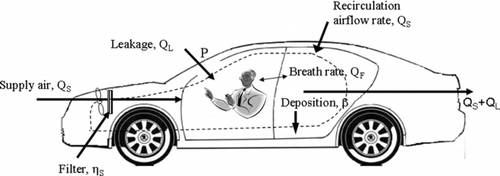
illustrates schematically important processes that influence the in-cabin UFP concentrations. Outdoor UFPs enter the in-cabin microenvironment through two pathways: mechanical air supply, at a flow rate of Q S (m3 h−1), and leakage, at a flow rate of Q L (m3 h−1). For the mechanical air supply, UFPs have to pass a filter whose particle collection efficiency is η S (−). UFPs that go through the leakage flow pathway may not all enter the vehicle either, only a fraction of particles, P (−), can penetrate. UFPs inside the vehicle will be lost onto the interior surfaces by a deposition loss coefficient β (h−1). Human respiration, Q F (m3 h−1), including inhalation and exhalation, may also contribute to the in-cabin UFP level changes. There is a filtration efficiency η F (−), which denotes the fraction of UFP removed by human respiratory system during breathing.
FIG. 1 Schematic representation of in-cabin particle dynamic processes. When the Fan is on and RC off, the outdoor air goes through a filter and the cracks on the doors into the cabin (solid line). When Fan and RC are both on, the air recirculated inside the vehicle is by passing through an in-cabin filter (dashed line).
Since the model addresses vehicular-emitted UFPs, other potential in-cabin UFP emission sources such as smoking and secondary aerosol formation were not considered in this study. Three ventilation settings were tested in the model following experimental conditions reported in CitationZhu et al. (2007) in which data were collected from vehicles driving on freeways under (1) Fan off-recirculation (RC) off, (2) Fan on–RC off, and (3) Fan on–RC on, with window closed all the time. Assuming there is no resuspension, coagulation or other particle phase-change phenomena; Equation (Equation1) is the mathematical model for size-dependent in-cabin UFP mass concentrations by incorporating processes presented in . Equation (Equation1) also assumes the in-cabin microenvironment is a well-mixed interior. Although Equation (Equation1) was originally based on particle mass and material balances, it can be used to simulate size-dependent particle number concentration I/O ratios by assuming same density for each specific particle size both inside the vehicle and outside on the freeway. Under steady state, Equation (Equation2) is the analytical solution for Equation (Equation1) for each specific particle size. When outdoor UFP concentration changes dramatically over a short period of time, which is not uncommon for on-roadway measurement, Equation (Equation1) can be solved numerically with respect to outdoor UFP concentration variations by using a time-step approach that is presented in the discussion section.
Where, for a particular size bin (d j ), C mij (g cm−3) is the in-cabin mass concentration, C moj (g cm−3) is the on-freeway mass concentration, C ij (number cm−3) is the in-cabin number concentration, C0j (number cm−3) is the on-freeway number concentration, and V (m3) is the vehicle interior volume. P j , η Sj , η Fj , and β j are penetration factor, filtration efficiency, removal fraction by respiratory, and deposition coefficient in the same size bin.
Under different ventilation settings, i.e., (1) Fan off-RC off; (2) Fan on–RC off; and (3) Fan on–RC on, Equation (Equation2) needs to be modified with respect to air exchange pathways between the in-cabin and the external environment. For example, under condition (1), there is no mechanical air supply (Q
S
= 0) and Equation (Equation2) is reduced to ![]() . summarizes the applicable equations under different ventilation settings.
. summarizes the applicable equations under different ventilation settings.
TABLE 1 Equations used in the in-cabin mathematical model under different ventilation settings
Mechanical Airflow (Q S ) and Leakage Airflow (Q L )
Ventilation is the process of exchanging air between the in-cabin and the outside. The mechanical flow rate is calculated by multiplying the cross-sectional area of the vehicle outlet vents and the air velocity coming out of the vents. Generally, there are 4–6 outlet vents in a vehicle, and the cross-sectional area of each one is about 40–60 cm2. The average air velocity across the vent area was measured to be in the range of 0 to 6 m s−1 from fan off to the highest fan speeds by a flow meter (AVM-01, PROVA Inc., Taiwan). The mechanical airflow rate was then estimated to vary from 0 to 360 m3 h−1. During the CitationZhu et al. (2007) experiments, fan speeds were set at an intermediate level of 1.8 m s−1corresponding to a mechanical airflow of 108 m3 h−1.
Leakage airflow, driven by the pressure difference between the in-cabin and the outdoor environment, also brings external air into the vehicle. It changes with respect to vehicle ages, ventilation settings, vehicle makers and models, and driving speed. Leakage airflow is relatively stable for the same vehicle under the same ventilation setting driving on different roadways (CitationZhu et al. 2007). Few studies have been published focusing on leakage flow in vehicles. However, leakage flow from building cracks has been studied and can be calculated using the following equation (CitationBaker et al. 1987).
Penetration Factor (P)
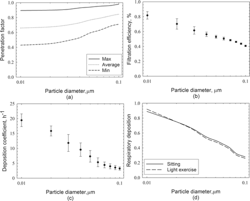
As analogous to buildings, the vehicle penetration factor (P) is defined as the fraction of UFPs of a specific diameter which pass through the vehicle shell with the infiltrating air. Although uncertainties still existed in current analysis on vehicle penetration factors, both model and experiment studies on particle penetration through building cracks have been published (CitationLiu and Nazaroff 2001; Citation2003). These studies found that the penetration factor ranged from 0.5 to 0.9 for a wide range of particle sizes. Previously published data were based on the assumption that the crack widths were 3, 4.3, and 9.4 cm, which were somewhat different from those in vehicles. For cracks in vehicles, because the main leakage airflow goes through the cracks between the door and frame, the crack width is the thickness of the door which is close to 4 cm. Thus, penetration factors for 4.3 cm crack width, z in Equation (Equation3), were applied to the model. illustrates penetration factors over studied UFP size ranges.
FIG. 3 Size-segregated ranges of important input parameters for the in-cabin model (a) penetration factor (CitationLiu and Nazaroff 2003), (b) filtration efficiency (CitationQi et al. 2008), (c) deposition coefficient (CitationGong et al. 2009), and (d) respiratory deposition fraction (CitationHinds 1999).
Mechanical Filtration Efficiency (η S )
The mechanical ventilation system in a modern vehicle is frequently equipped with a filter to provide “fresh” air into the vehicle. Describing the fraction of UFPs captured in the filter, the filter efficiency (η S ) is expected to change sharply in the studied UFP size range. Recently, direct measurements of filtration efficiency for in-cabin filters in the UFP size range were published (CitationQi et al. 2008) and applied as the model input in this study. presents the filtration efficiency as a function of particle diameters. Data presented in were collected at two different face air velocities (10.8 cm s−1 and 21.5 cm s−1) (CitationQi et al. 2008).
Deposition Coefficient (β)
Deposition is one of the particle loss mechanisms inside vehicles. Although particle deposition onto indoor surfaces have been studied extensively (CitationOffermann et al. 1985; CitationThatcher et al. 2002; CitationThatcher et al. 2003; CitationVette et al. 2001), there are limited relevant experimental data (CitationOtt et al. 2007) or theoretical models to provide the exact value of deposition coefficient inside vehicles. Airflow speed and surface area are two main factors determining the deposition coefficient (CitationThatcher et al. 2002), and these factors are quite different between the in-cabin and the indoor microenvironments. In-cabin air exchange rates, 1.9–48.5 h−1 (CitationOtt et al. 2007), are much greater than those found in typical indoor environments which are usually on the order of 0.5 h−1 (CitationMurray and Burmaster 1995). The airflow velocity was also found to be much greater inside vehicles than indoors (Gong et al. 2008). Thus, indoor particle deposition coefficient data could not be applied directly to the in-cabin model. Instead, we measured deposition coefficient with respect to particle size and in-cabin air velocity. Detailed description of the deposition experiment set up and results were presented in CitationGong et al. (2009). presents average particle deposition coefficients measured inside three different vehicles as a function of particle size (Gong et al. 2008).
Human Respiration (Q F, ηF)
People sitting inside vehicles inhale and exhale UFP laden air that may potentially affect the I/O ratios. Due to human respiratory deposition, there is a net loss of UFPs inside the vehicle. shows the respiratory deposition coefficient for different size particles (CitationHinds 1999). The respiratory deposition coefficient can be viewed as analogous to the filter collection efficiency where the driver and passengers inside the vehicle act as air cleaners in rooms. A breathing rate, QF, of 0.5 m3 h−1 was used in the model representing an average sitting person (CitationHinds 1999). Three persons were presented during the CitationZhu et al. (2007) experiment.
RESULTS AND DISCUSSION
It should be noted that all the input parameters (e.g., penetration factor, filtration efficiency, deposition coefficient) are size-dependent (). Therefore, the I/O ratio was calculated for individual particle size by adopting the input parameters for that particular size from into the relevant governing equations. compares model predicted I/O ratios with measured data under different ventilation settings. The shaded areas are the model range due to uncertainties in model input parameters such as vehicle speed which varied from 50 to 70 mph as reported in CitationZhu et al. (2007). As shown in , the modeled results matched experimental data very well. As the ventilation settings changed from Fan off- RC off, to Fan on–RC off, and to Fan on–RC on, the measured I/O ratios decrease across all particle sizes and so did the modeled results. In , the maximum (top lines of shaded areas) and minimum (bottom lines of shaded areas) values in the model were calculated by adopting different values of relevant parameters into the equations given in . Under condition (1), the I/O ratio is directly proportional to the penetration factor (P). Therefore, the maximum model result was calculated by using the largest P in . By differentiating Equation (Equation2) with respect to Q L , it was found that the I/O ratio was proportional to Q L when it is positive. Thus, the largest Q L was used to calculate the maximum I/O ratio. All the maximum and minimum values in were calculated in the same way. This approach was also used to analyze the relative importance of individual model input parameter on the I/O ratios, as discussed later.
FIG. 4 Model results and measured data under (a) Fan off and RC off, (b) Fan on and RC off, and (c) Fan on and RC on conditions. Volume of the vehicle is 6 m3. The speed of vehicle is from 50 to 70 mph.
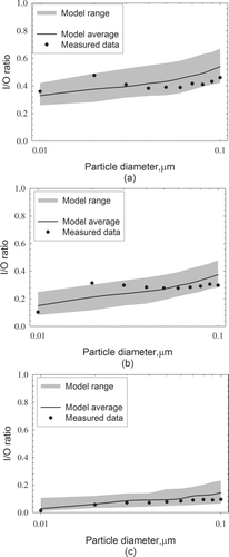
It is noted in , the trend that the model predicted does not match the measured data exactly under all ventilation conditions. The measured I/O ratios were more constant with respect to the particle diameters than the model predicted. This is likely due to the fact that vehicular emitted UFPs are not homogeneous and particle phase change may occur during the process. For example, UFPs around 50 nm may lose their volatile components and become smaller ones as observed in a previous indoor UFP study near roadways (CitationZhu et al. 2005). Another reason for the discrepancy between modeled results and measured results is the parameter differences between model inputs and the experimental conditions. When “fan off, RC off” (), penetration factor was the dominant parameter that determined I/O ratio and was higher for larger UFPs in the model. However, because the test vehicle was a well-sealed new vehicle, the air exchange by penetration was quite little, and so did the impact of penetration factor. Therefore, there was no significant difference of I/O ratio among different particle sizes in the experimental data. Particle deposition during penetration may also lead to the discrepancies for larger particles, and needs further investigation. On the other hand, in , modeled result matches measured result very well. This is because under this particular ventilation condition, no single parameter dominated the modeled I/O ratios. Future studies are needed to address these uncertainties in the model input parameters.
Besides matching reasonably well with the size-segregated I/O data reported by CitationZhu et al. (2007), the modeled total particle I/O ratios agree with data from other recent studies. CitationGouriou et al. (2004) found that under condition (1), the total particle number I/O ratios were between 10–70% when running on hilly roads (CitationGouriou et al. 2004). CitationKaur et al. (2006) measured human exposure to UFPs in cars, buses and taxis and found that the total particle number I/O ratios in the car were between 43% and 70% (CitationKaur et al. 2006). presents non-steady-state model results by using one-minute, the SMPS scanning time, as a time step. Equation (Equation1) was modified into Equation (Equation4) from which dynamic model results can be achieved. In Equation (Equation4), C′ ij is the in-cabin concentration for particle diameter d j at the end of each minute, Cij is the in-cabin concentration for particle diameter d j at the beginning of each minute, one-minute is used as dt, and all other parameters were the same as those in Equation (Equation1). C′ ij was continuously calculated by plugging Cij that was calculated from the last time interval and the other parameters into Equation (Equation4). Then the in-cabin concentrations of all particle sizes were added up to achieve the modeled in-cabin UFP concentrations. With measured on-freeway data (CitationZhu et al. 2007), the dynamic change of in-cabin UFP concentrations were calculated and presented in and compared with the experiment data. As shown in , the modeled in-cabin UFP concentrations were sensitive to the on-freeway levels, followed on-freeway concentration changes, and agreed with the measurement data very well. A small rise or drop of the outdoor concentrations changed both modeled and measured in-cabin UFP levels immediately.
FIG. 5 Dynamic simulation of the in-cabin UFP concentrations compared with the measurement data (CitationZhu et al. 2007).
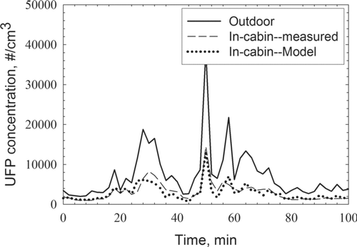
From and , one can see the model developed in this study simulate the experimental data well under both steady- and dynamic-state. In the following sections, the relative importance of each model input parameter on the I/O ratios was analyzed by changing one parameter at a time while keeping the others the same in broader categories of vehicle cabin microenvironments. In order to investigate how different size particles were affected differently by each parameter, three particle sizes (20 nm, 50 nm, and 80 nm) were selected to represent small, medium, and large UFPs.
Mechanical Airflow Rate and Filtration Efficiency
, , and present the modeled I/O ratios as a function of the mechanical airflow rate in the range of 0–360 m3h−1 for 20, 50, and 80 nm particles, respectively. When the fan is on, the mechanical air supply dominates the in-cabin air quality and determines the I/O ratios. The airflow rate and filtration efficiency are covariant which affect each other in the model; the faster the airflow passes through, the lower the filtration efficiency. The modeled I/O ratios were found to be inversely proportional to the mechanical airflow rate below 108 m3 h−1 under various ventilation settings. In the range of 108–360 m3 h−1, trends of the I/O ratios are affected by ventilation settings besides particle sizes. Under condition (2), the I/O ratios are proportional to the mechanical flow rate (Q S ). Under condition (3), the trends of the I/O ratios depend on whether the airflow rate or the filtration efficiency changes more sharply with respect to the particle size. After calculating the product of the airflow rate and the filtration efficiency (QS η S ), it was found that QS η S was inversely proportional to the mechanical airflow rate. Therefore, the I/O ratio decreased when the mechanical flow rate increased.
FIG. 6 Ranges of I/O ratios at different mechanical air flow rates for (a) 20 nm, (b) 50 nm, and (c) 80 nm particles. Airflow rate: max = 360 m3h−1, min = 0 m3 h−1. Drivers usually set the ventilation flow rate at a medium range, as “common situation” shown in the figure. All other parameters are set to average. Volume of vehicle is 6 m3. The speed of vehicle is 60 mph.
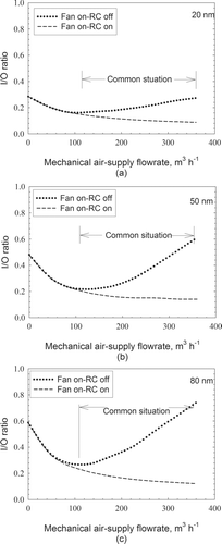
The effects of mechanical airflow rate on the I/O ratio for different size particles are different. Under conditions (2) and (3), less change in I/O ratios was observed for smaller particles than larger ones. This is because the filtration efficiency changes slightly when the mechanical airflow increases for 20 nm particles, but sharply for 50 nm and 80 nm particles. Both the mechanical airflow and the filtration efficiency are important factors under condition (2), but play less important roles under condition (1).
Penetration
Penetration is another important process affecting the in-cabin I/O ratios as shown in . Under condition (1), penetration is the only way for the external air to flow into the vehicle. As shown by the solid lines in , , and , the differences between the maximum and the minimum I/O ratios are all greater than 15%. Under conditions (2) and (3), the difference between the maximum and the minimum I/O ratios decreases to less than 10%. Under these conditions, the mechanical ventilation becomes the main pathway for air exchange between the in-cabin and the outside.As shown in , changing from one ventilation condition to another affects the 80 nm particles more significantly than the 20 nm ones. This is because other input parameters affect I/O ratios differently for different size particles. Under condition (1), the gradient of the I/O ratio change as a function of the penetration factor for 80 nm particles is the greatest because the deposition coefficient for the 80 nm particles is the smallest (). When the fan is on, larger filtration efficiencies (η S ) for larger UFPs contribute to larger I/O ratios besides the penetration factors.
FIG. 7 Ranges of I/O ratios at different penetration factors for (a) 20 nm, (b) 50 nm, and (c) 80 nm particles. Penetration factors in the range of “previous studies” follow , and all other parameters are set to the average. Volume of vehicle is 6 m3. The speed of vehicle is 60 mph.
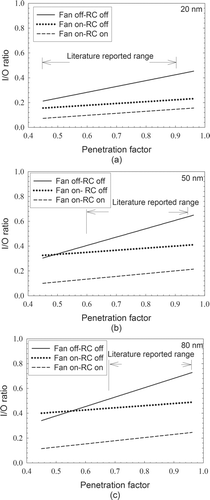
To achieve a complete picture of the effect of the penetration factors on the I/O ratios, model results presented in covered a wider range of penetration factors than previously reported data in the literature as indicated in the figure (i.e., 0.45–0.9 for 20 nm, 0.6–0.94 for 50 nm, and 0.68–0.96 for 80 nm) (CitationVette et al. 2001). It should be noted, the penetration factors used in this paper were adopted from indoor studies. Differences of key physical processes, such as the materials between the frame and the door and the shape of the cracks, exist between the in-cabin and indoor environments and deserve further investigation.
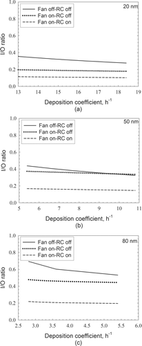
Deposition
indicates that the deposition coefficient is as important as the other two factors discussed above. The range of measured deposition coefficients (13.2–18.5 h−1 for 20 nm, 5.4–9.3 h−1 for 50 nm, 3.1–4.8 h−1for 80 nm) reported by CitationGong et al. (2009) was used in the model to investigate the effect of deposition coefficient on the I/O ratio. The greatest difference between the maximum and the minimum I/O ratios caused by deposition is about 10%–15%, when both Fan and RC are off (solid lines in ). Under conditions (2) and (3), the difference is less than 5%, suggesting the effect of deposition coefficient on the I/O ratio becomes negligible when the fan is on. The effect of deposition coefficient on the I/O ratio for larger particles is greater than that for smaller ones.
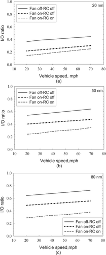
Vehicle Speed
Vehicle speed directly affects the differential pressure between the ambient and the in-cabin environments, which determines the leakage flow rate. As shown in , for all three ventilation settings, faster driving may cause more leakage resulting in higher I/O ratios. However, the relative importance of vehicle speed under different ventilation settings is different. When there is no mechanical air supply from outside in the vehicle (conditions (1) and (3)), leakage plays a predominant role for the air exchange resulting in a greater effect. Under condition (2), vehicle speed has a less significant effect on the I/O ratios (dotted lines in ). At the same vehicle speed, although the differential pressure between the outdoor and the in-cabin remains the same, larger penetration factor of larger particles causes more particles leaking into the vehicle with the same amount of infiltration air. Therefore, under all three ventilation settings, I/O ratios for 80 nm particles are the greatest.
Human Respiration
From a material-balance perspective, human respiratory system serves as an “air cleaner” inside the vehicle. Equations in indicate that the I/O ratio increases when the amount of air breathed by the people decreased. However, we found there was no significant difference between one and five people sitting inside the vehicle under all three ventilation conditions. Compared with either the leakage or the mechanical process, the airflow of respiration is nearly zero under all ventilation settings when the vehicle speed is at 60 mph. Under extreme conditions, when vehicles move very slowly or even stop, such as in a traffic jam, only deposition and respiration contribute to in-cabin UFP concentration changes. By comparing deposition loss βV with respiration loss QF η F , it was found that the total particle loss was 40–210 times greater by deposition than by respiration. Therefore, even under extreme conditions, respiratory deposition is still not an important factor in changing the in-cabin UFP concentrations.
In-Cabin UFP Concentration Delay
A vehicle on a freeway can be viewed as a chamber. When the on-freeway UFP concentration changes, the in-cabin UFP concentration does not change immediately because the supply air which carries the UFPs into the vehicle needs some time to mix with the reserve air before a new balance between the in-and-out of the vehicle is established. After integrating Equation (Equation1) with respect to time, t, the in-cabin UFP concentration delay can be calculated.
illustrates the in-cabin UFP concentration delay under different ventilation settings, when the outdoor UFP concentrations were increased by 2, 5, and 10 times, respectively. When the outdoor UFP concentration rises by a factor of five, under condition (1), it takes the longest time, about 88–187, for the in-cabin UFP concentration to achieve a new balance. Under condition (ii), it only takes 7–56 s, which is similar to previously reported experimental results (CitationZhu et al. 2007). Under condition (3), the time delay is between 10 and 70 seconds.
FIG. 10 Time delays under different ventilation settings when outdoor UFP concentration changed to 2, 5, and 10 times what it was. The speed of vehicle is 60 mph.
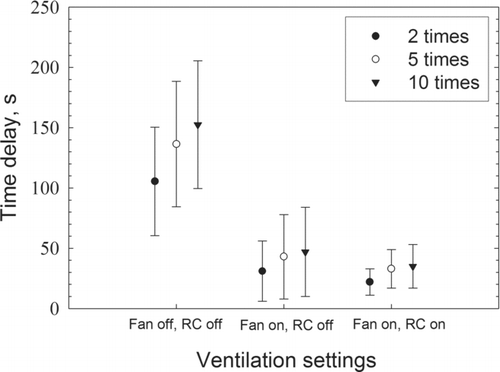
The time it takes for the in-cabin air to achieve a new balance depends on the ventilation settings, the penetration factor and the filtration efficiency. The greater amount of the in-cabin air exchanged with the ambient air, the faster the in-cabin particle concentration reaches the new balance. In addition, under conditions (2) and (3), the I/O ratios are lower than under condition (1) which means the total amount of particles needed to achieve the new balance is less and so does the time.
CONCLUSIONS
The method presented in this article is useful in predicting the in-cabin to on-roadway UFP concentration ratios. Under condition (1) (Fan off–RC off, solid lines in , , ), within the literature-reported parameter ranges, the key factors which influence the I/O ratios are penetration factors (15–25%), deposition coefficients (10–15%), and vehicle speeds (∼15%). Under condition (2) (Fan on–RC off, dotted lines in , , , ), a combination of the filtration efficiency and the mechanical ventilation airflow rates dominate (∼50%), while penetration factors (∼10%) and vehicle speeds (∼8%) play secondarily important roles. Under condition (3) (Fan on–RC on, dashed lines in , , , ), the I/O ratio is affected by vehicle speeds (∼15%), mechanical airflow rates (∼8%), and penetration factors (∼8%). The predominant factors under each ventilation condition are summarized in .
Acknowledgments
This material is based upon work partially supported by the Center of Research Excellence in Science and Technology—Research on Environmental Sustainability of Semi-Arid Coastal Areas (CREST-RESSACA) at Texas A&M University—Kingsville through a Cooperative Agreement (No. HRD-0734850) from the National Science Foundation. Any opinions, findings, and conclusions or recommendations expressed in this material are those of the authors and do not necessarily reflect the views of the National Science Foundation. Bin Xu would like to thank China Scholarship Council for his scholarship under the State Scholarship Fund.
REFERENCES
- Baker , P. , Sharples , S. and Ward , I. 1987 . Air-Flow Through Cracks . Building and Environment , 22 : 293 – 304 .
- Chan , A. T. and Chung , M. W. 2003 . Indoor-Outdoor Air Quality Relationships in Vehicle: Effect of Driving Environment and Ventilation Modes . Atmos. Environ. , 37 : 3795 – 3808 .
- Gouriou , F. , Morin , J. P. and Weill , M. E. 2004 . On-Road Measurements of Particle Number Concentrations and Size Distributions in Urban and Tunnel Environments . Atmos. Environ. , 38 : 2831 – 2840 .
- Gong , L. , Xu , B. and Zhu , Y. 2009 . Ultrafine Particles Deposition Inside Passenger Vehicles . Aerosol Sci. Technol. , in press
- Qi , C. , Stanley , N. , Pui , D. Y. H. and Kuehn , H. 2008 . Laboratory and On-Road Evaluations of Cabin Filters Using Number and Surface Area Concentration Monitor . Environ. Sci. Technol. , 42 : 4128 – 4132 .
- Hinds , W. C. 1999 . Aerosol Technology: Properties, Behavior, and Measurement of Airborne Particles , New York : Wiley .
- Kaur , S. , Clark , R. , Walsh , P. , Arnold , S. J. , Colvile , R. N. and Nieuwenhuijsen , M. 2006 . Exposure Visualisation of Ultrafine Particle Counts in a Transport Microenvironment . Atmos. Environ. , 40 : 386 – 398 .
- Leung , P. L. and Harrison , R. M. 1999 . Roadside and In–Vehicle Concentrations of Monoaromatic Hydrocarbons . Atmos. Environ. , 39 : 191 – 204 .
- Liu , D. L. and Nazaroff , W. W. 2001 . Modeling Pollutant Penetration Across Building Envelopes . Atmos. Environ. , 35 : 4451 – 4462 .
- Liu , D. L. and Nazaroff , W. W. 2003 . Particle Penetration Through Building Cracks . Aerosol Sci. Technol. , 37 : 565 – 573 .
- Murray , D. M. and Burmaster , D. E. 1995 . Residential Air Exchange Rates in the United States: Empirical and Estimated Parametric Distributions by Season and Climatic Region . Risk Anal. , 15 : 459
- Nazaroff , W. W. 2004 . Indoor Particle Dynamics . Indoor air , 14 : 175 – 183 .
- Oberdorster , G. , Ferin , J. and Gelein , R. 1992 . Role of Alveolar Macrophage in Lung Injury: Studies with Ultrafine Particles . Environ. Health Perspect. , 97 : 193 – 199 .
- Oberdorster , G. , Sharp , Z. , Atudorei , V. , Elder , A. , Gelein , R. , Lunts , A. , Keyling , W. and Cox , C. 2002 . Extrapulmonary Translocation of Ultrafine Carbon Particles Following Whole-Body Inhalation Exposure of Rats . J. of Toxicol. Environ. Health—Part A , 65 : 1531 – 1543 .
- Oberdorster , G. , Sharp , Z. , Atudorei , V. , Elder , A. , Gelein , R. , Keyling , W. and Cox , C. 2004 . Translocation of Inhaled Ultrafine Particles to the Brain . Inhalation Toxicol. , 16 : 437 – 445 .
- Offermann , F. J. , Sextro , R. G. , Fisk , W. J. , Grimsrud , D. T. , Nazaroff , W. W. , Nero , A. V. , Revzan , K. L. and Yater , J. 1985 . Control of Respirable Particles in Indoor Air with Portable Air Cleaners . Atmos. Environ. , 19 : 1761 – 1771 .
- Ott , W. N. K. and P , S. 2007 . Air Change Rates of Motor Vehicles and In-Vehicle Pollutant Concentrations from Secondhand Smoke . J. Eposure Sci. Environ. Epidemiol. , 17 : 1 – 14 .
- Riley , W. , McKone , T. , Lai , A. and Nazaroff , W. 2002 . Indoor Particulate Matter of Outdoor Origin: Importance of Size-Dependent Removal Mechanisms . Environ. Sci. Technol. , 36 : 200 – 207 .
- Shair , F. H. and Heitner , K. L. 1974 . Theoretical Model for Relating Indoor Pollutant Concentrations to Those Outside . Environ. Sci. Technol. , 8 : 444 – 451 .
- Thatcher , T. L. , Lai , A. C. K. , Moreno-Jackson , R. , Sextro , R. G. and Nazaroff , W. W. 2002 . Effects of Room Furnishings and Air Speed on Particle Deposition Rates Indoors . Atmos. Environ. , 36 : 1811 – 1819 .
- Thatcher , T. L. , Lunden , M. M. , Revzan , K. L. , Sextro , R. G. and Brown , N. J. 2003 . A Concentration Rebound Method for Measuring Particle Penetration and Deposition in the Indoor Environment . Aerosol Sci. Technol. , 37 : 847 – 864 .
- Vette , A. F. , Rea , A. W. , Lawless , P. A. , Rodes , C. E. , Evans , G. , Highsmith , V. R. and Sheldon , L. 2001 . Characterization of Indoor-Outdoor Aerosol Concentration Relationships During the Fresno PM Exposure Studies . Aerosol Sci. Technol. , 34 : 118 – 126 .
- Westerdahl , D. , Fruin , S. , Sax , T. , Fine , P. M. and Sioutas , C. 2005 . Mobile Platform Measurements of Ultrafine Particles and Associated Pollutant Concentrations on Freeways and Residential streets in Los Angeles . Atmos. Environ. , 39 : 3597 – 3610 .
- Zhu , Y. , Eiguren-Fernandez , A. , Hinds , W. C. and Miguel , A. 2007 . In–Cabin Commuter Exposure to Ultrafine Particles on Los Angeles Freeways . Environ. Sci. Technol. , 41 : 2138 – 2145 .
- Zhu , Y. , Hinds , W. C. , Krudysz , M. , Kuhn , T. , Froines , J. and Sioutas , C. 2005 . Penetration of Freeway Ultrafine Particles into Indoor Environments . J. Aerosol Sci. , 36 : 303 – 322 .
- Zhu , Y. F. , Hinds , W. C. , Shen , S. and Sioutas , C. 2004 . Seasonal Trends of Concentration and Size Distribution of Ultrafine Particles Near Major Highways in Los Angeles . Aerosol Sci. Technol. , 38 : 5 – 13 .

