Abstract
Fibers with elliptical cross-sections have higher surface to volume ratios than those with circular cross-sections and may therefore lead to increased filter collection efficiency. Single-fiber theory and velocity flow fields developed for elliptical fibers can be used to predict collection efficiency by diffusion for elliptical fibers. Utilizing the convective diffusion equation in elliptical coordinates, single-fiber diffusion efficiency was calculated for 4,312 combinations of cross-section aspect ratio, filter solidity, orientation of the cross-section to the air flow, and Peclet number. An empirical expression was developed from the results of these model runs to predict single-fiber diffusion efficiency for any combination of conditions. The equation indicates that diffusion efficiency is most strongly influenced by the Peclet number because decreases in particle size and increases in air velocity affect diffusion substantially. Increases in aspect ratio and solidity also increase the diffusion efficiency by making more fiber surface available for collection. Although the angle of orientation has the least effect of any of the factors, elliptical fibers with the major axis of the cross-section parallel to the incoming flow may have performance advantages over circular fibers if the angle of orientation can be controlled during filter production. This is because some elliptical fibers with the major axis parallel to the incoming flow have both higher single-fiber diffusion efficiency and less drag than circular fibers.
Nomenclature
| Dp | = |
particle diffusion coefficient |
| K0 | = |
hydrodynamic number |
| K2 | = |
factor similar to Ku from CitationRaynor (2002) |
| Ku | = |
Kuwabara number |
| lf | = |
length of major axis of elliptical fiber cross-section |
| L | = |
filter thickness |
| n* | = |
non-dimensional particle number concentration |
| Pe | = |
Peclet number for circular fibers |
| PeE | = |
Peclet number for elliptical fibers |
| Re | = |
Reynolds number |
| U | = |
face velocity for the filter |
| wf | = |
length of minor axis of elliptical fiber cross-section |
| α | = |
filter solidity |
| β1–β12 | = |
parameters from Equation (Equation18) |
| Δ θ | = |
orientation angle |
| ϵ | = |
aspect ratio |
| ηD | = |
single-fiber diffusion efficiency for fibers with circular cross-sections |
| ηD,E | = |
single-fiber diffusion efficiency for fibers with elliptical cross-sections |
| ηF | = |
single-fiber efficiency for fibers with circular cross-sections |
| ηF,E | = |
single-fiber efficiency for fibers with elliptical cross-sections |
| ηI | = |
single-fiber impaction efficiency for fibers with circular cross-sections |
| ηI,E | = |
single-fiber impaction efficiency for fibers with elliptical cross-sections |
| ηR | = |
single-fiber interception efficiency for fibers with circular cross-sections |
| ηR,E | = |
single-fiber interception efficiency for fibers with elliptical cross-sections |
| ηT | = |
total filter efficiency for filters made from fibers with circular cross-sections |
| ηT,E | = |
total filter efficiency for filters made from fibers with elliptical cross-sections |
| φ | = |
φ-coordinate in elliptical coordinate system |
| χ | = |
χ-coordinate in elliptical coordinate system |
| χc | = |
χ-coordinate of outer boundary of solution domain |
| χf | = |
χ-coordinate of fiber surface |
| Ψ* | = |
non-dimensional stream function |
INTRODUCTION
Fibrous filters successfully limit emissions of airborne particles into occupational and ambient environments. They are used in heating, ventilating, and air-conditioning (HVAC) and local exhaust ventilation systems to reduce airborne particle levels in the environment, and in respirators to protect workers from occupational exposures to particles. Fibrous filter media are also used for a variety of industrial hygiene sampling applications.
Fibrous filters can be described as mats of randomly arranged fibers where most of the fibers are roughly perpendicular to the air flow through the filter. The filters are usually highly porous to allow efficient air movement. Filter fibers are made from many materials and in many shapes. Commonly used materials include natural fibers such as cotton and wool, fiberglass, synthetic fibers made from thermoplastic polymers, and blends such as cellulose-ester fibers. Although most commercial fibers have circular cross-sections, fibers with elliptical, lobed, and wedge-shaped cross-sections are available (CitationHutten 2007). Filters made from these various fibers may be configured as pads, pleated papers, bonded webs, nettings, or composites.
Filtration of airborne particles occurs when particles contact and attach to the fibers that make up the filter. Collection efficiency, the fraction of particles entering a filter that are captured, depends on flow and filter properties such as the velocity of air through the filter, thickness of the filter, filter solidity or packing density, fiber size, and fiber shape. Particle size and shape also influence efficiency. The primary mechanical filtration mechanisms are impaction, interception, diffusion, and gravitational settling (CitationBrown 1993). Gravitational settling occurs when the ratio of the settling velocity to the air velocity is large enough for a significant percentage of the particle to drop onto the fibers. This mechanism is frequently disregarded when considering filtration of respirable particles. Electrostatic effects also enhance filtration when particles are attracted to fibers carrying surface charges. Neither gravitational settling nor electrostatic attraction will be considered further in this article.
Single-fiber theory is utilized to predict how each collection mechanism contributes to efficiency and how properties such as particle diameter, filter solidity, air velocity, and fiber diameter influence collection by the individual mechanisms. Particle capture by single fibers is related to the overall efficiency of a filter according to the properties of the fibers and filter. The theory assumes that the air flow is perpendicular to the fiber axis; that the Reynolds number, Re, for flow around the fiber is less than 1; and that each particle that contacts the fiber sticks to the fiber and is permanently removed from the air stream (CitationHinds 1999). To allow calculations of collection efficiency by individual fibers for each mechanism, flow fields have been developed for air movement around fibers with circular cross-sections (CitationKuwabara 1959) and around those with elliptical cross-sections (CitationRaynor 2002).
For circular fibers, the overall efficiency for the filter, ηT, can be calculated from the single-fiber efficiency, ηF, using either the equation
The single-fiber efficiency can be approximated by taking the sum of the efficiencies for each filtration mechanism. For circular fibers this is
Collection by diffusion occurs when small particles deviate from air streamlines due to Brownian motion and attach to fibers. Brownian motion is caused by the random collisions of the particles with surrounding gas molecules. Collisions from surrounding molecules on particles whose diameter is similar to or smaller than the mean free path between the air molecules does not occur evenly around the particle, allowing the particle to move randomly among the gas molecules. Larger particles do not experience the degree of random movement that occurs with smaller particles because the net force from surrounding molecules is distributed more evenly across the larger particle surface, minimizing the particle motion.
For fibers with circular cross-sections, it has been shown that diffusion efficiency is governed by the Peclet number, Pe, defined as
CitationMasliyah (1975) used numerical modeling to evaluate the potential for filters made from fibers with elliptical cross-sections to perform better than filters made from fibers with circular cross-sections. After evaluating the efficiency and drag for elliptical fibers with aspect ratios of 5 and either the major or minor axis oriented parallel to the flow, the author concluded that the use of elliptical fibers did not offer benefits beyond circular fibers for collection by diffusion. This work, however, was limited to special cases of Peclet number, aspect ratio, and orientation of the fiber to incoming flow and did not utilize the angular component of diffusion when solving the convective diffusion equation.
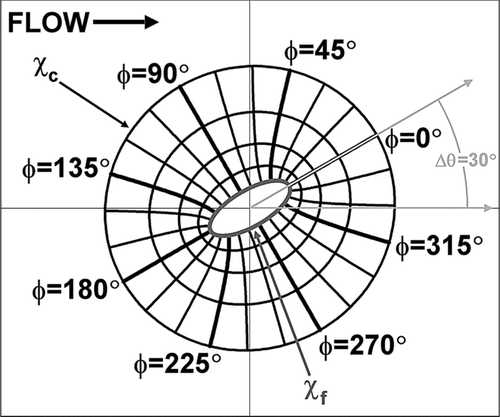
Using the elliptical coordinate system (χ, φ) illustrated in , CitationRaynor (2002) developed a flow field around fibers with elliptical cross-sections that varied as a function of α; the aspect ratio of the fiber cross-section, ϵ; and the angle of orientation of the cross-section to the free stream flow, Δ θ. The purpose of the present study was to use this expression to determine the single-fiber diffusion efficiency for elliptical fibers. The approach taken was to create a numerical model for calculating diffusion efficiency based on Raynor's flow field, run it repeatedly as a function of variations in the relevant parameters, and develop an empirical expression that accurately predicts the numerical modeling results. The empirical equation could then be used in future work to optimize efficiency for filters made with elliptical fibers. The expression may also be useful for ribbon-shaped fibers and rectangular fibers with large aspect ratios.
FIG. 1 An example of a solution domain for flow and diffusion efficiency calculations. This domain is for a filter with a solidity of 0.04 and an elliptical fiber with an aspect ratio of 2.5 and angle of orientation relative to the incoming flow (Δ θ) of 30°. The elliptical coordinate system (χ, φ) is superimposed on the domain with curves of constant χ being ellipses and curves of constant φ being hyperbolas. The elliptical surfaces of the inner boundary (the fiber) and outer boundary of the domain are indicated by χf and χc, respectively.
METHODS
Single-fiber diffusion efficiency, ηD,E, will depend on α, ϵ, Δ θ, and PeE, the Peclet number for elliptical cross-sections, which can be defined as
Equation (Equation14) was discretized using finite difference methods. First and second derivatives were approximated using second-order central difference formulas involving adjacent cells. The solution domains like the ones in for flow fields around fibers were discretized into 101 values of χ and 180 values of φ to produce a system of 18,180 equations. The equations were solved using Fortran 90 (Fortran PowerStation, Microsoft Corporation, Redmond, WA) for all 4,312 combinations of the values for α, ϵ, Δ θ, and PeE shown in . The minimum value of ϵ is set to 1.001 rather than 1 because terms in the flow field equation specified by CitationRaynor (2002) are undefined at ϵ = 1. The boundary conditions for the Fortran program were n* = 1 for air entering the region surrounding the fiber, ∂2n* /∂ χ2 = 0 for air exiting the region around the fiber, and n* = 0 on the surface of the fiber.
TABLE 1 Input values utilized for diffusion efficiency Fortran program
The diffusion efficiency was calculated by dividing the rate of particle deposition onto the fiber surface by the rate at which particles would pass through a line segment, (lf wf)½ long and perpendicular to the incoming flow, if the fiber were not present. The term (lfwf)½ is the diameter of a fiber with a circular cross-section having the same area as the cross-section of the elliptical fiber being evaluated. Particle deposition was calculated using a third-order approximation of particle flux at each of the 180 values of φ on the fiber surface. The flux equation for each value of φ utilized concentrations at the three values of χ closest to the surface for that φ.
To automate running the Fortran program, a Microsoft Visual Basic program was written to input each possible combination of α, ϵ, Δ θ, and PeE, direct the model to run a set number of the input combinations, and output the results into a Microsoft Excel spreadsheet.
The modeling results were used to develop an empirical equation to predict diffusion efficiency for filters made with elliptical fibers. Data analysis was initiated by graphing computed values of ηD,E against the four independent variables—α, ϵ, Δ θ, and PeE—separately for the 4,312 variable combinations. The graphs were evaluated to examine the influence of each factor on diffusion efficiency and to determine functions of the parameters that would best linearize the influence of each factor on ηD,E.
Using PROC GLM in SAS 9.1.3 (SAS Institute, Cary, NC), the natural logarithms of computed values of ηD,E were modeled against functions of the parameters that appeared to linearize the dependence of ln(ηD,E) upon the parameters and their interactions. The goal of this process was to find an empirical expression that predicted ηD,E accurately as a function of α, ϵ, Δ θ, and Pe E . Multiple iterations were run, changing the parameter combinations to refine the equation in an attempt to find the best possible fit.
RESULTS
The parameter functions ultimately included in the expression for ln(ηD,E) developed from the results of the numerical computations were ln(Pe), ln(K2), ln(ϵ), and sin2(Δ θ). The factor K2, defined as
After taking the exponential of both sides of the expression developed for ln(ηD,E), the final equation to predict single-fiber diffusion efficiency for fibers with elliptical cross-sections has the form
TABLE 2 Estimated values and 95% confidence intervals of the estimates for terms β1–β12 in Equation (Equation18)
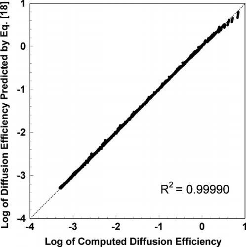
For all 4,312 sets of factors modeled numerically using the Fortran program, shows the base 10 logarithm of the diffusion efficiency calculated from Equation (Equation18) plotted against the logarithm of the efficiency predicted using the program. The R2 for this correlation is 0.99990, indicating that Equation (Equation18) predicts the computed diffusion efficiency well. No prediction from Equation (Equation18) differed by more than 31% from the value computed numerically. Moreover, 99.8% of the predictions were within 20% of the computed values, 98.1% were within 10%, and 91.0% were within 5%.
FIG. 2 The logarithm of single-fiber diffusion efficiency predicted using empirically developed Equation (Equation18) plotted against the logarithm of diffusion efficiency computed directly using numerical methods. Predictions from Equation (Equation18) correlate with the computations with R2 = 0.99990.
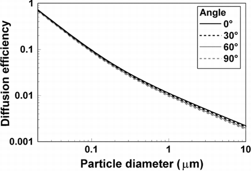
The influence of spherical particle diameter on ηD,E is shown in as predicted by Equation (Equation18) for Δ θ ranging from 0° to 90°. Other parameters are set at ϵ = 6, α = 0.016, U = 5 cm/s, and (lf wf)½ = 3 μ m. The slip correction factor used to determine the particle diameter from the diffusion coefficient associated with each value of Pe was taken from CitationKim et al. (2005). In all cases shown in the figure, the diffusion efficiency decreases as the particle diameter increases, and the particle diameter has a much more significant influence on ηD,E than Δ θ does. At these conditions, single-fiber diffusion efficiency is affected little by orientation angle. For particles with diameters larger than 0.1 μ m, ηD,E decreases only slightly as Δ θ increases from 0° to 90°.
FIG. 3 Single-fiber diffusion efficiency versus particle diameter for several orientation angles. In all cases, aspect ratio is 6, solidity is 0.016, incoming velocity is 5 cm/s, temperature is 21.1°C, and the cross-sectional area is equivalent to that of a circular fiber with a 3 μ m diameter, about 7.07 μ m2.
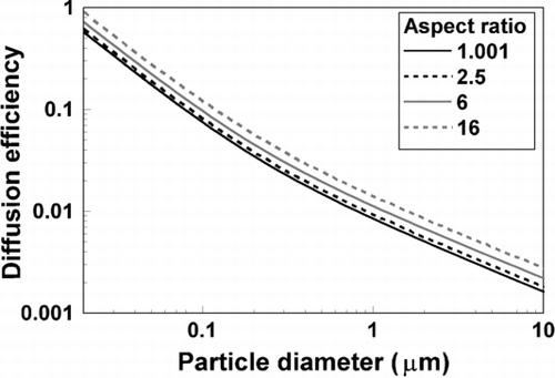
The relationship between ηD,E and particle diameter for ϵ = 1.001, 2.5, 6, and 16 is shown in for Δ θ = 90°, α = 0.016, U = 5 cm/s, and (lf wf)½ = 3 μ m. shows the same comparison except that Δ θ = 0° rather than 90°. Both figures indicate that ηD,E increases as ϵ increases. In addition, the efficiency increases more between ϵ = 2.5 and ϵ = 6 than it does between ϵ = 1.001 and ϵ = 2.5, and even more between ϵ = 6 and ϵ = 16 than it does between ϵ = 2.5 and ϵ = 6.
FIG. 4 Single-fiber diffusion efficiency versus particle diameter for several aspect ratios. In all cases, orientation angle is 90°, solidity is 0.016, incoming velocity is 5 cm/s, temperature is 21.1°C, and the cross-sectional area is equivalent to that of a circular fiber with a 3 μ m diameter, about 7.07 μ m2.
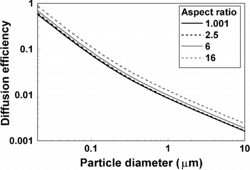
FIG. 5 Single-fiber diffusion efficiency versus particle diameter for several aspect ratios. In all cases, orientation angle is 0°, solidity is 0.016, incoming velocity is 5 cm/s, temperature is 21.1°C, and the cross-sectional area is equivalent to that of a circular fiber with a 3 μ m diameter, about 7.07 μ m2.
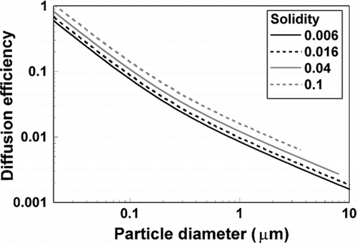
illustrates the dependence of ηD,E on α. The figure shows efficiency as a function of diameter for four values of α with ϵ = 6, Δ θ = 90°, U = 5 cm/s, and (lf wf)½ = 3 μ m. Some diameters for α = 0.04 and 0.1 are not plotted on this figure because the center of the particle is unable to enter the solution domain due to the relatively large diameters of the particles. The single-fiber diffusion efficiency increases noticeably as α increases.
FIG. 6 Single-fiber diffusion efficiency versus particle diameter for several values of solidity. In all cases, aspect ratio is 6, orientation angle is 90°, incoming velocity is 5 cm/s, temperature is 21.1°C, and the cross-sectional area is equivalent to that of a circular fiber with a 3 μ m diameter, about 7.07 μ m2.
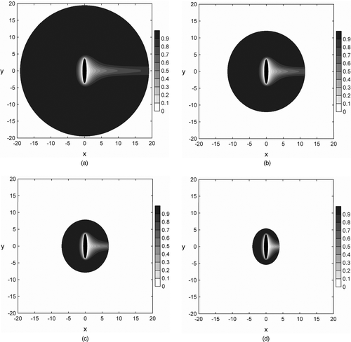
, , , present concentration profiles caused by diffusive collection of particles 0.05 μ m in diameter on single fibers calculated within the solution domain by the Fortran program for conditions corresponding, respectively, to , , , . In all cases, air is flowing from left to right and particles enter the solution domain at a uniform concentration. Darker areas represent higher concentrations whereas lighter areas indicate lower concentrations.
FIG. 7 Concentration profiles due to collection by diffusion on single fibers for particles 0.05 μ m in diameter plotted for conditions corresponding to . Orientation angles are (a) 0°, (b) 30°, (c) 60°, and (d) 90°. In all cases, aspect ratio is 6, solidity is 0.016, incoming velocity is 5 cm/s, temperature is 21.1°C, and the cross-sectional area is equivalent to that of a circular fiber with a 3 μ m diameter. Air flow is from left to right and the x and y axes have units of μ m. The scale indicates non-dimensional particle concentrations ranging from an inlet concentrations of 1 to concentrations at the fiber surface of 0.
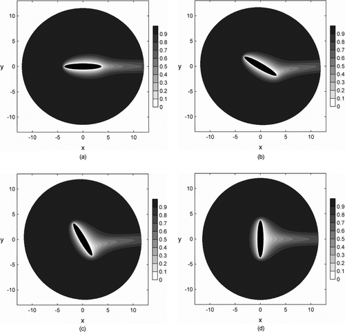
FIG. 8 Concentration profiles due to collection by diffusion on single fibers for particles 0.05 μ m in diameter plotted for conditions corresponding to . Aspect ratios are (a) 1.001, (b) 2.5, (c) 6, and (d) 16. In all cases, orientation angle is 90°, solidity is 0.016, incoming velocity is 5 cm/s, temperature is 21.1°C, and the cross-sectional area is equivalent to that of a circular fiber with a 3 μ m diameter. Air flow is from left to right and the x and y axes have units of μ m. The scale indicates non-dimensional particle concentrations ranging from an inlet concentrations of 1 to concentrations at the fiber surface of 0.
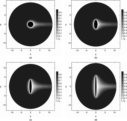
FIG. 9 Concentration profiles due to collection by diffusion on single fibers for particles 0.05 μ m in diameter plotted for conditions corresponding to . Aspect ratios are (a) 1.001, (b) 2.5, (c) 6, and (d) 16. In all cases, orientation angle is 0°, solidity is 0.016, incoming velocity is 5 cm/s, temperature is 21.1°C, and the cross-sectional area is equivalent to that of a circular fiber with a 3 μ m diameter. Air flow is from left to right and the x and y axes have units of μ m. The scale indicates non-dimensional particle concentrations ranging from an inlet concentrations of 1 to concentrations at the fiber surface of 0.
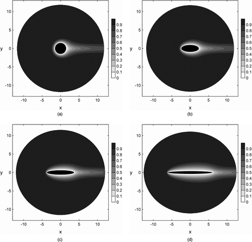
FIG. 10 Concentration profiles due to collection by diffusion on single fibers for particles 0.05 μ m in diameter plotted for conditions corresponding to . Solidity values are (a) 0.006, (b) 0.016, (c) 0.04, and (d) 0.1. In all cases, aspect ratio is 6, orientation angle is 90°, incoming velocity is 5 cm/s, temperature is 21.1°C, and the cross-sectional area is equivalent to that of a circular fiber with a 3 μ m diameter. Air flow is from left to right and the x and y axes have units of μ m. The scale indicates non-dimensional particle concentrations ranging from an inlet concentration of 1 to concentrations at the fiber surface of 0.
DISCUSSION
, , , show that single-fiber diffusion efficiency with elliptical fibers increases as particles decrease in size. This finding matches the expectation that large particles do not move as readily by Brownian motion as smaller particles, and therefore are not collected as efficiently by diffusion. The figures indicate nearly a 3 order of magnitude decrease in diffusion efficiency over a 3 order of magnitude increase in particle diameter.
and demonstrate that elliptical cross-section fibers have higher collection efficiency by diffusion than circular cross-section fibers and that the efficiency increases as aspect ratio gets larger. and and diffusion theory suggest that this increased collection by diffusion may be due to the larger surface area of the fiber for the same cross-sectional area as aspect ratio increases.
presents results of calculations that support the hypothesis that increased surface area of large aspect ratio fibers contributes to higher efficiency. For each aspect ratio presented in , , , and , the circumference of the fiber was calculated as a surrogate for surface area. Next, the percentage increase in circumference relative to ϵ = 1.001 was determined. For each aspect ratio, diffusion efficiency was calculated from Equation (Equation18) for particles with a diameter of 0.05 μ m. Then, the percentage increase in efficiency relative to the efficiency for ϵ = 1.001 was figured. Finally, the increase in efficiency for every 10% increase in fiber circumference was calculated for each aspect ratio. The calculations indicate that each 10% increase in fiber surface area due to increases in fiber aspect ratio leads to about a 3% increase in efficiency.
TABLE 3 Results of calculations associated with the influence of aspect ratio and elliptical fiber circumference on single-fiber diffusion efficiency, ηD,E. Calculations were performed with orientation angle = 90°, solidity = 0.016, incoming air velocity = 5 cm/s, and cross-sectional area equal to that of a circular fiber with a diameter = 3 μ m
A less influential factor in determining the diffusion efficiency is the angle of orientation. shows little change in efficiency as the angle varies. For particles smaller than 1 μ m in diameter, which have the highest diffusion efficiency, almost no differences are observed with angle. However, for larger particles, the efficiency decreases slightly as orientation angle increases from 0° to 90°. These modest differences are probably due to alterations in the flow field as the fiber orientation changes.
As indicated in , an increase in solidity or packing density of the filter also increases the diffusion efficiency. suggests that the reason for higher efficiency at higher packing density is that a greater fraction of the particles enters the solution domain close enough to the fiber to be able to diffuse to the fiber's surface.
indicates that Equation (Equation18) fits the modeled data well. Furthermore, more than two-thirds of the combinations of conditions for which the difference between a computed efficiency and a prediction from Equation (Equation18) is greater than 10% are for conditions yielding a single-fiber diffusion efficiency greater than 1. In these cases, small errors in single-fiber diffusion efficiency predictions from Equation (Equation18) mean little because essentially all particles will be collected within a typical filter consisting of many layers of fibers throughout its depth. Most of these outliers are associated with combinations of the highest solidity, 0.18, and either the highest aspect ratios of 10 or 15 or the smallest Peclet number, 3. These parameter values are the most challenging for computing diffusion efficiency with the Fortran program. The combination of a small domain at high solidity, small clearance around the ends of the fiber cross-section at high aspect ratios, and large diffusivities when Peclet numbers are small leads to almost complete collection of particles. Therefore, single fiber diffusion efficiency may be limited by the dimensions of the solution domain and the fiber when almost all particles are captured. These somewhat artificial constraints on large values of diffusion efficiency may have been difficult to capture with Equation (Equation18) and may have contributed to the outliers in for the highest efficiencies.
The Fortran model used in this study assumes that the concentration of particles becomes 0 only on the fiber surface, ignoring the dimensions of the particles and therefore the effects of interception of diffusing particles. Interception efficiency for fibers with elliptical cross-sections has been calculated by CitationRaynor (2008). However, the combined effects of interception and diffusion are greater than the sum of the effects of each mechanism taken individually. Calculations for circular fibers by CitationDavies (1973) based on theory developed by CitationStechkina and Fuchs (1966) indicate that failure to consider the combined effects of interception and diffusion leads to the greatest inaccuracies for particles with diameters near a filter's most penetrating particle size, typically 0.3 μ m for purely mechanical filters. Because the combined effect of interception and diffusion is more difficult to compute than the effect of each mechanism individually, it will be considered separately in future research.
When Raynor (2002) developed the flow fields around elliptical fibers assuming air moving past the fiber is a continuum, he employed a boundary condition of zero velocity, or no slip, on the fiber surface. However, as the dimensions of the fiber approach the mean free path of the air molecules, the assumption of a continuum is less accurate and the potential for slip flow on the fiber surface arises. CitationKirsch and Chechuev (1985) conducted experiments to study the importance of accounting for slip flow in computations of single-fiber diffusion efficiency and concluded that theory developed without consideration of slip flow is suitable for ultrafine particles and fibers as long as Pe ≥ 0.5, which includes all conditions evaluated in this study. Therefore, the effects of slip flow are not included in Equation (Equation18).
A filter that performs better than an existing one will have higher efficiency for the same pressure drop or lower pressure drop at the same efficiency. Equation (Equation18) and indicate that the use of elliptical cross-section fibers at 0° orientation in filter construction will yield filters with higher diffusion efficiency than filters made from fibers with circular cross-sections of the same area. In addition, calculations from CitationRaynor (2002) indicate that fibers with aspect ratios of 2.5 and 6 will exhibit slightly less drag at 0° orientation than a circular fiber with the same cross-sectional area, whereas the drag on a fiber with an aspect ratio of 15 will be slightly greater than the drag on a circular fiber. Thus, filters made from elliptical fibers with a 0° orientation may have both higher efficiency for particles collected primarily by diffusion (typically particles with diameters smaller than 0.3 μ m) and, for some aspect ratios, lower pressure drop. This suggests that elliptical fibers may perform better than circular fibers in some cases if the major axis of the elliptical cross-sections can be aligned parallel to the direction of air flow. Strategies for constructing filters in this manner are recommended if collection of submicrometer particles is of importance.
CONCLUSIONS
An empirical equation was developed to predict the diffusion efficiency for filter fibers that have elliptical cross-sections. The equation was developed from multiple runs of a Fortran model predicting collection of particles by elliptical fibers as a function of aspect ratio of the fiber cross-section, the angle of orientation of the fiber to the air flow, the solidity of the filter, and the Peclet number which accounts for particle diameter and air velocity. The suitability of the expression was demonstrated by comparing the modeled diffusion efficiency values to the predicted values. As with circular fibers, diffusion efficiency decreases with increasing particle diameter. In addition, diffusion efficiency is greater for elliptical fibers having larger aspect ratios, regardless of the angle of orientation. This is a key finding that suggests that elliptical fibers may have filter performance advantages relative to circular fibers in some situations, depending on the importance of other efficiency mechanisms and fiber drag. Although the angle of orientation has little influence on diffusion efficiency, the efficiency is enhanced when the filters are packed tightly. The expression for diffusion efficiency can be programmed into a computer spreadsheet for easy repetitive calculations.
Acknowledgments
The authors would like to thank Mark Collins for his help in automating the modeling task.
REFERENCES
- Brown , R. C. 1993 . Air Filtration , 73 – 119 . Oxford : Pergamon Press .
- Cheng , Y. S. , Yamada , Y. and Yeh , H. C. 1990 . Diffusion Deposition on Model Fibrous Filters with Intermediate Porosity . Aerosol Sci. Technol. , 12 : 286 – 299 .
- Davies , C. N. 1973 . Air Filtration , 74 – 77 . London : Academic Press .
- Hinds , W. C. 1999 . Aerosol Technology, Properties, Behavior, and Measurement of Airborne Particles, , 2nd ed. , 190 – 196 . New York : Wiley-Interscience .
- Hutten , I. M. 2007 . Handbook of Nonwoven Filter Media , 103 – 194 . Amsterdam : Elsevier .
- Kim , J. H. , Mulholland , G. W. , Kukuck , S. R. and Pui , D. Y. H. 2005 . Slip Correction Measurements of Certified PSL Nanoparticles Using a Nanometer Differential Mobility Analyzer (Nano–DMA) for Knudsen Number From 0.5 to 83 . J. Res. Natl. Inst. Stan. , 110 : 31 – 54 .
- Kirsch , A. A. and Chechuev , P. V. 1985 . Diffusion Deposition of Aerosol in Fibrous Filters at Intermediate Peclet Numbers . Aerosol Sci. Technol. , 4 : 11 – 16 .
- Kuwabara , S. 1959 . The Forces Experienced by Randomly Distributed Parallel Circular Cylinders or Spheres in a Viscous Flow at Small Reynolds Numbers . J. Physical Society Japan , 14 : 527 – 532 .
- Lee , K. W. and Liu , B. Y. H. 1982 . Theoretical Study of Aerosol Filtration by Fibrous Filters . Aerosol Sci. Technol. , 1 : 147 – 161 .
- Masliyah , J. 1975 . Aerosol Removal by Diffusion and Interception in Mats of Elliptic Fibres . Can. J. Chem. Eng. , 53 : 568 – 571 .
- Natanson , G. L. 1957 . Diffusion Precipitation of Aerosols on a Streamlined Cylinder with a Small Capture Coefficient (English Translation) . Proc. Acad. Sci. USSR Phys. Chem. , 112 : 21 – 25 .
- Raynor , P. C. 2002 . Flow Field and Drag for Elliptical Filter Fibers . Aerosol Sci. Technol. , 36 : 1118 – 1127 .
- Raynor , P. C. 2008 . Single–Fiber Interception Efficiency for Elliptical Fibers . Aerosol Sci. Technol. , 42 : 357 – 368 .
- Stechkina , I. B. and Fuchs , N. A. 1966 . Studies on Fibrous Aerosol Filters—I. Calculation of Diffusional Deposition of Aerosols in Fibrous Filters . Ann. Occup. Hyg. , 9 : 59 – 64 .