Abstract
This study concerns filtration of sub-micron aerosol using dual nanofiber and microfiber layers. The first part compares the filtration performance of nanofiber (300 nm diameter fibers) and microfiber (1.8 μm diameter fibers) filters. Test aerosol is sodium chloride (NaCl) particulates ranging from 41 to 514 nm generated from atomization. Experimental results show that the fractional efficiency and quality factor of nanofiber filter is higher than microfiber filter, but microfiber filter has lower rate of increase in pressure drop under continuous loading. The second part aims to utilize the dust holding capacity of microfiber filter to relieve the rapid clogging and skin formation of nanofiber filter. In this work, three types of filters formed by stacking of microfiber and nanofiber layers are tested to investigate the loading characteristics of inhomogeneous dual-layer fibrous filter under the challenge of sub-micron NaCl aerosol. Experimental results show that the filter with microfiber layer upstream of nanofiber layer has a lower increase rate in pressure drop than the filter with constituent layers in reversed arrangement. The semi-empirical model of polydisperse aerosol loading, as modified from the version of monodisperse aerosol, predicts deposition profile across filter depth that explains the pressure drop results. Serving two purposes, the dual-layer filter with microfiber (upstream) and nanofiber (downstream) is able to utilize the strength of nanofibers in clean stage filtration and microfibers in loaded stage filtration. Moreover, a lower pressure drop increase implies that the filter does not require frequent cleaning by backpulses of compressed air, which might destroy the fragile nanofibers.
INTRODUCTION
Fibrous filter is a cost-effective means for the collection of particulates from gas stream. Filter quality mainly depends on filtration efficiency and gas permeability. In order to improve filter quality, filter media should be highly permeable while still have filtration efficiency above the level as required by environmental standards or end-users. One of the possible ways to improve filter quality is to fabricate fine fibers with diameter down to nano-scale (so-called nanofibers), which can be traced back to the clean filter pressure drop model proposed by Pich in 1966. CitationLee et al. (2006) have developed nanofiber filters made of electrospun Nylon 6 fibers with diameter below 200 nm and compared them against HEPA filter. CitationTsai et al. (2002) reported that the amount of residual charge on electrospun fibers depends on the polymer used, while those with good charge retention property can be fabricated into electret filter media. In addition, Gradoń et al. (2005), Podgórski et al. (2006), and CitationPodgórski (2009) have found that a composite of nanofibrous and microfibrous filters has significantly increased efficiency at the most penetrating particle size (MPPS) and improved quality factor as compared to conventional microfibrous filters. The above studies focused on performance evaluation of clean nanofiber filter not loaded with aerosol, and their findings favored the use of nanofiber filters. Leung and Hung (2008) reported that under continuous filtration of sub-micron aerosol, pressure drop across nanofiber filter rises at a much faster rate than microfiber filter despite the former has a better aerosol capture efficiency. The fast increase of pressure drop across nanofiber filter means frequent cleaning of the filter by backpulses of compressed air (CitationCallé et al. 2001), thus leading to higher energy consumption and increased chance of destroying the fragile nanofibers by the air jet. To reduce the pressure drop increase rate of nanofiber filter media, a microfiber filter can be placed upstream forming an inhomogeneous dual-layer filter. This arrangement of fibrous layers is opposite to the one studied thoroughly by Gradoń et al. (2005), Podgórski et al. (2006), CitationPodgórski (2009), and CitationPrzekop and Gradoń (2008). The upstream microfiber layer helps to collect part of the aerosol challenging the filter, thus suppress the increase rate of pressure drop of downstream nanofiber layer. The effectiveness of this inhomogeneous filter will be assessed through a series of tests performed in this study.
The loading characteristics of inhomogeneous filters (also homogeneous ones) largely depend on their deposition profile across filter depth. From a semi-empirical approach, CitationBrown and Wake (1999), also CitationPodgórski (1998), have proposed the concept of linear loading within a filter slice to predict the deposition profile across the depth of a homogeneous fibrous medium loaded with monodisperse aerosol. Their predictions show agreement to efficiency test results. However, the situation complicates in our study when the inhomogeneous dual-layer filters are challenged by polydisperse aerosol. Hence, the approach from CitationBrown and Wake (1999) and CitationPodgórski (1998) will be modified in the present work. The assumptions and shortcomings of this approach will be addressed subsequently. Since our deposition model is semi-empirical, constituent filter layers will be tested individually first to determine all necessary empirical constants, one of which is the fractional efficiency raising factor (CitationSakano et al. 2000).
SEMI-EMPIRICAL MODEL ON DEPOSITION PROFILE WITH POLYDISPERSE AEROSOL
By assuming the mass efficiency of a filter slice being linearly related to the deposited mass as a first approximation, CitationBrown and Wake (1999) and CitationPodgórski (1998) have derived an expression on the deposition profile of a homogeneous fibrous filter under continuous filtration of monodisperse aerosol. It should be noted that mass efficiency refers to the ratio between mass of collected aerosol and mass of challenging aerosol, and is equivalent to fractional efficiency only in the case of monodisperse aerosol. When an inhomogeneous dual-layer filter is loaded continuously by polydisperse aerosol, the expression can still be used to predict the deposition profile of upstream layer, but not the case for downstream layer due to the size distribution of aerosol stream leaving the upstream layer changing with time with consequence of an unsteady inlet condition in the downstream layer. As a start, the expression on deposition profile as obtained by CitationBrown and Wake (1999) and CitationPodgórski (1998) will be adopted, followed by deriving an equation for solving the fractional efficiency raising factors. Using the fractional efficiency raising factors, the size distribution of aerosol stream leaving the upstream layer will be determined subsequently. The deposition profile of downstream layer can be predicted accordingly.
The expressions on mass concentration C m (x, t) and deposition profile M(x, t) across filter depth (x) after loading for t units of time, obtained by CitationBrown and Wake (1999) and CitationPodgórski (1998), are given as follows:
Substitute x = L (where L is the filter thickness) into Equation (Equation1), it can be re-written as:
While M 0 is regarded as the constant relating mass efficiency and deposit mass, the fractional efficiency raising factor λ(D p ) is regarded as the constant relating fractional efficiency for a given aerosol size D p and deposit mass. Analogous to M 0, λ(D p ) has to be determined empirically from fractional efficiencies η(D p , t) sampled at regular time interval during the loading process. Suppose the filter is partitioned into N slices along its thickness, η(D p , t) and the fractional efficiency of each slice in the filter η sl (D p , x i , t) are related by Equation (Equation4):
Substituting Equation (Equation5) into Equation (Equation4) yields:
After obtaining λ (D p ) of constituent filter layers, the deposition profile M(x, t) of an inhomogeneous dual-layer filter is predicted from the following approach:
The deposition profile M(x, t) is then determined according to Equation (Equation10):
By integrating M(x, t) along filter thickness L, the mass of deposit per unit filter area W(t) can be obtained:
EXPERIMENTS
The properties of constituent filter layers are listed in . Filters A, B, and C are nanofiber filters while filter D is a microfiber filter. The nanofiber filters used in this study are fabricated by coating a nanofiber web on an extremely porous coarse fibrous structure (mean fiber diameter of 14.7 μ m). The coarse fibrous structure acts as a framework for anchoring of nanofibers and offers negligible fractional efficiency and flow resistance under the test conditions. Thickness of nanofiber web is obtained by subtracting supporting framework thickness from nanofiber filter. The clean filter packing density c f is calculated from Davies empirical formula given by Equation (Equation13):
TABLE 1 Properties of constituent filter layers
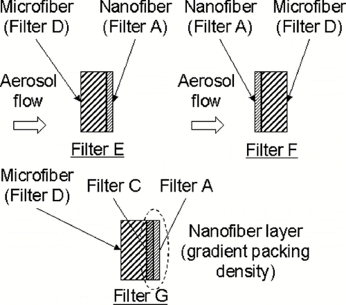
The stacking of constituent filter layers within the dual-layer filters (filters E, F, and G) to be tested is depicted in . Filter G is also an inhomogeneous dual-layer filter, but its nanofiber layer has a gradient packing density by stacking filters A and C, with the more porous (i.e., lower c f ) layer C upstream to the less porous (i.e., higher c f ) layer A.
Sub-micron aerosol generator (SMAG, model 7388L, MSP Corp., Shoreview, MN) containing an atomizer and electrostatic classifier is used to generate sodium chloride (NaCl) test aerosol ranging from 41 to 514 nm diameter. Condensation particle counter (CPC, model 3010, TSI Inc., Shoreview, MN) is used to measure particle concentration. Pressure drop across test filter is measured by capillary flow porometer (CFP, model CFP–1100A, PMI, Ithaca, NY). Filter thickness is measured by micrometer. Face velocity in the test is adjusted to 5 cms−1 through the throttle valve on the rotameter. Make-up air stream is filtered by HEPA filter to ensure that no particle species other than NaCl are present in the aerosol stream. Isokinetic sampling tube is used for getting representative readings of particle concentrations. Mean fiber diameter is estimated from pictures obtained by scanning electron microscope (SEM).
The test filter is first soaked in iso-propyl alcohol for 5 minutes for discharging and then air-dried. The test filter is then installed within an air-tight test rig and tested for clean filter fractional efficiency with NaCl particles ranging from 41 to 514 nm diameter. The experimental set-up is identified as scheme 1 in . CPC is used to measure particle number concentration at filter upstream and downstream alternatively. Multiple charge effect is corrected in order to obtain the actual particle number concentration.
FIG. 2 Schematic of experimental set-up for testing of fractional efficiency (scheme 1) and loading up test filter (scheme 2).
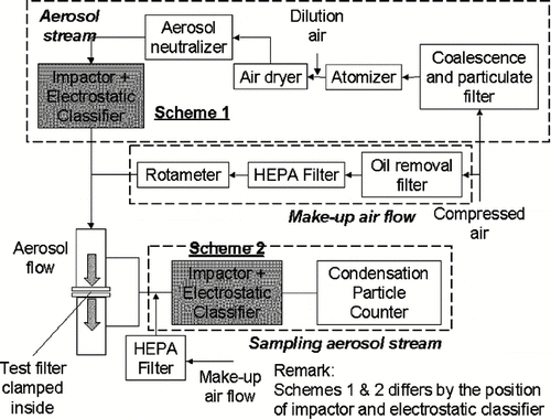
After testing for clean filter fractional efficiency using monodisperse NaCl aerosol, the test filter is loaded continuously by neutralized (actually bi-polar charged close to equilibrium charged) polydisperse NaCl aerosol generated from atomization. Particle size distribution at filter upstream is measured by electrostatic classifier and CPC operating in scanning mode and maintained at a constant level. Increase in pressure drop is monitored throughout the loading process. The experimental set-up for loading up the test filter by polydisperse aerosol is identified as scheme 2 in . Fractional efficiency is measured at regular time interval by switching the set-up back to scheme 1 as depicted in .
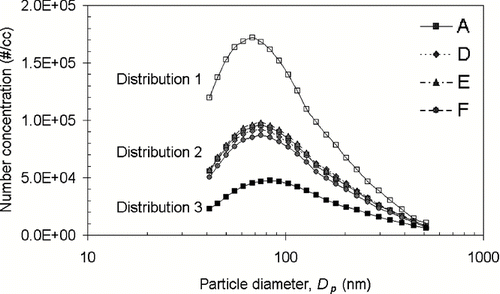
shows the size distribution of aerosol stream loading up filters A, D, E, and F. All filters in this study are loaded up by aerosol stream of similar size distribution. However, filter A has been selected to be loaded by three different aerosol size distributions in order to validate the semi-empirical model. Empirical terms α0, M 0 and λ(D p ) as determined from loading test under distribution 2 are used to predict the filtration efficiency under distributions 1 (higher concentration, smaller mode) and 3 (lower concentration, larger mode).
RESULTS AND DISCUSSION
Clean Filter
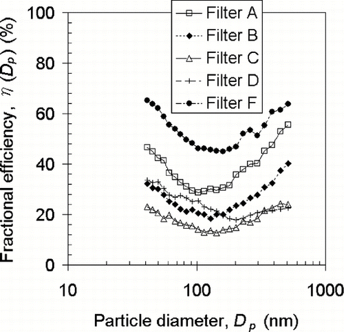
The fractional efficiencies of clean filters A to D, and F are depicted in . The improved efficiency and reduced MPPS of filter A (nanofiber) as compared to filter D (microfiber) is attributed to enhanced interception mechanism, implying that nanofiber filter with more surface area per unit volume of fiber is more capable of capturing particles through the mechanism of interception rather than microfiber filter. MPPS of clean filters A, B and C are 103, 128, and 143 nm, respectively. Again, reduced MPPS and increased efficiency from filters C to A is attributed to enhanced interception mechanism with increasing nanofiber surface area. The MPPS of filter F is 160 nm, which lies between that of filters A (103 nm) and D (203 nm). Filter F is formed by stacking nanofiber and microfiber filters, with nanofiber filter facing upstream. This arrangement is identical to the composite that has been studied thoroughly by Gradoń et al. (2005) and Podgórski et al. (2006), and their findings on increased efficiency and reduced MPPS of composite as compared to conventional microfibrous filters are observed in our study.
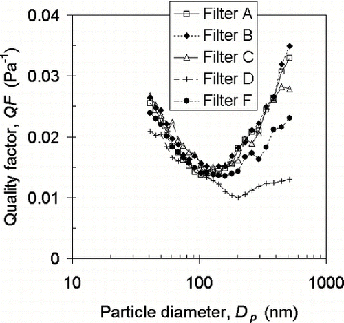
shows the quality factor (QF) of clean filters A to D, and F. QF is defined as:
Loaded Filter
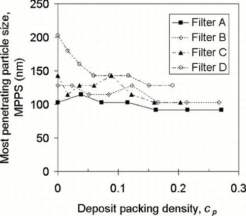
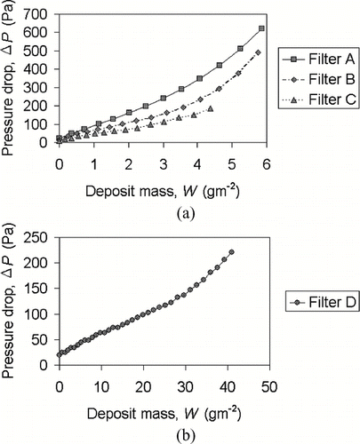
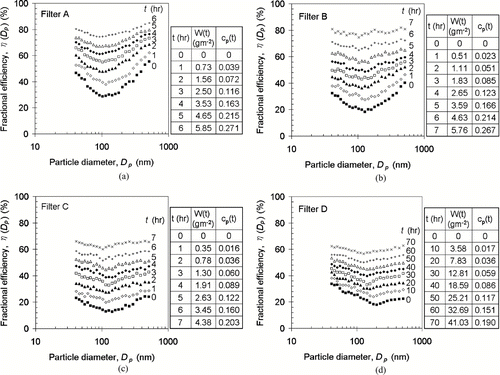
The fractional efficiencies of filters A to D under continuous loading of sub-micron NaCl aerosol ranging from 41 to 514 nm are shown in , , , , respectively. Note that the solid squares marked with “0” on right hand side represent the clean filter fractional efficiencies. For microfiber filter D, fractional efficiencies increase and the MPPS shifts to smaller sizes after loading. This can be explained by the fact that aerosol deposit improves filtration efficiency through interception and diffusion, with interception effect more prominent between the two mechanisms. However, the fractional efficiency curve of nanofiber filters A to C shift upward almost parallel to each other under continuous loading. It is postulated that aerosol deposit in nanofiber filter provides interception and diffusion capture effect on comparable scale, in contrast to microfiber filter. W(t) and c p (t) values in the legend on , , , , are determined according to Equations (Equation11) and (Equation12), respectively. Deposit packing density c p represents the degree of loading. compares the change of MPPS among filters A to D under continuous loading. The MPPS of filters A, B, and C shifted down slightly from 103, 128, and 143 nm to 92, 103, and 103 nm, respectively; however, the MPPS of filter D shifted down from 203 to 128 nm after loading. The MPPS of microfiber filter decreases at a faster rate than nanofiber filter. Moreover, the MPPS of microfiber filter decreases monotonically, which is not the case for nanofiber filters. and show the pressure drop elevation of filters A to D under continuous loading. The nanofiber filters have pressure drop rises more rapidly than microfiber filter. also shows that nanofiber filters A, B, and C have different pressure drop under the same deposit mass. These loading characteristics are all related to the distribution of deposit, i.e., deposition profile, across filter depth.
FIG. 6 Fractional efficiencies of (a) filter A, (b) filter B, (c) filter C, and (d) filter D under continuous loading.
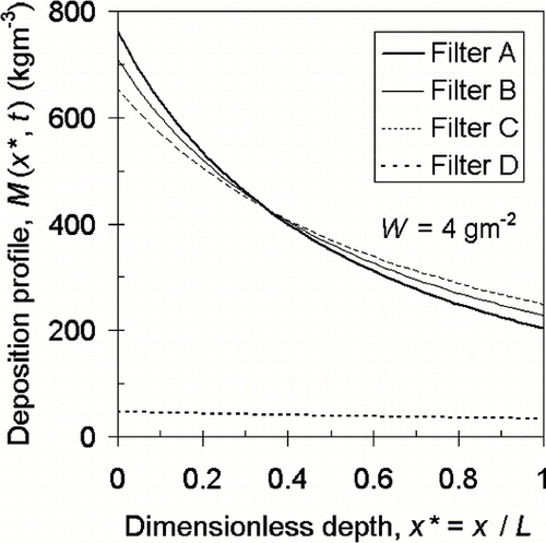
The deposition profile M(x*, t) under a deposit mass (W) of 4 gm− 2 is determined in . x* (= x/L, where L is the filter thickness) is used instead of x because filter D has thickness 10 times to that of filters A to C. M(x*, t) is predicted according to Equation (Equation2). As depicted in , aerosol deposit is distributed much more evenly across the depth of microfiber filter D than nanofiber filters A to C. It can be seen that when comparing between and , this uniform deposition profile leads to the much lower pressure drop increase rate of filter D. Hence, a nanofiber filter having higher filtration efficiency and quality factor than microfiber filter at clean stage (e.g., filter A outperforms filter D as shown in and ) does not suggest it to be the “absolutely” better filter. On the other hand, microfiber filters, by virtue of increased fiber diameter, are usually made thicker in order to achieve high filtration efficiency. The increased thickness facilitates dust holding, while a thin layer of nanofibers cannot achieve this objective. Among the nanofiber filters, filter C with the lowest c f (0.01078) shows the most uniform deposition profile, while filter A with the highest c f (0.02403) has the most uneven deposition across filter depth. Hence, filter C has lower pressure drop increase rate than filter A. As evident in , despite Δ P across filters A, B, and C at clean stage are at their low values—24.525, 14.715, and 9.81 Pa respectively, Δ P across filters A, B, and C loaded with 4 gm− 2 deposit become large—348, 235, and 142 Pa, respectively. It indicates that the increased flow resistance incurred by less porous nanofiber filter may not suit for long service due to the loaded fibers obstructing the gas flow. Hence, loading characteristics such as pressure drop increase rate should also be considered in filter design and selection, especially when nanofiber filters are used. While it is more significant for nanofiber filter and much less for microfiber filter, deposition profile is steep at face region (i.e., forming skin layer) and becomes moderate towards back region. This skin layer contributes to most of flow resistance across a loaded filter.
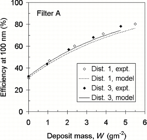
In order to validate the semi-empirical model, filter A has been loaded by polydisperse aerosol in three different size distributions as shown in . Empirical terms α 0, M 0, and λ(D p ) as determined from loading test under distribution 2 are used to predict the filtration efficiency under distributions 1 (higher concentration, smaller mode) and 3 (lower concentration, larger mode). shows the experimental and predicted efficiency at 100 nm particles. It can be seen that as loading continues, the semi-empirical model (line) slightly under-estimate the filtration efficiency (dots). However, the degree of under-estimation should be acceptable by considering the simplicity of the model.
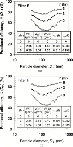
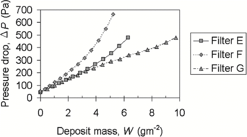
The filter layers are stacked to form the dual-layer filters as shown in . Filter E is formed by placing filter D upstream to filter A, aiming to relieve clogging in nanofiber layer, especially skin region, by utilizing the dust holding capacity of microfiber layer. Filter F serves as a control by placing filter A upstream to filter D, such that filters E and F have the same thickness, fractional efficiencies and pressure drop at clean stage. The dual-layer filters have undergone the same series of loading tests and their fractional efficiencies are shown in and . W A (t) and W D (t) are the deposit mass in filter layers A and D, respectively, while c pA (t) and c pD (t) are the deposit packing density in corresponding filter layers. At a first glance, filter E facilitates even distribution of deposit among microfiber and nanofiber layers, with W A (t) and W D (t) equal to 4.23 and 2.06 gm− 2 after loaded for 6 h. In contrast, filter F has the major portion of deposit being collected in its nanofiber layer, with W A (t) and W D (t) equal to 5.00 and 0.23 gm− 2 after loaded for 6 hours. For dual-layer filter, the shift of MPPS is not as obvious as microfiber filter. The sensitivity of fractional efficiency on particle diameter reduces as a result of loading. shows the elevation of pressure drop across loaded dual-layer filters. Pressure drop across filter E rises slower than filter F, first of all because microfiber layer in filter E helps to collect part of the challenging aerosol, thus reduces the loading and curtail the pressure drop elevation of downstream nanofiber layer. In contrast, filter F has its nanofiber layer under direct challenge of aerosol stream, where it clogs up rapidly.
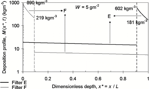
Deposition profile within individual layers also contributes to the distinct pressure drop increase rate between dual-layer filters E and F. compares the deposition profile M(x*, t) between filters E and F when W(t) is at 5 gm− 2. M(x*, t) of dual-layer filter is predicted from Equations (Equation9) and (Equation10) by adopting N = 50 for individual layers. Similar results can be achieved by adopting N = 25 and even N = 10. The only influence of choosing a larger N is that the predicted deposition profile is in higher resolution. It should be noted that M(x*, t) in y-axis of is in logarithmic scale since the deposit mass in microfiber layer is two orders of magnitude lower than that in nanofiber layer. M(x*, t) in nanofiber layer of filter F decreases from 890 kgm− 3 at face skin region to 219 kgm− 3 at back region, while filter E has this value decreases from 602 kgm− 3 at face skin region to 181 kgm− 3 across nanofiber layer thickness. The more uniform deposition profile across nanofiber layer in filter E leads to lower pressure drop increase rate.
In the following, the points that are somewhat hidden in the semi-empirical model on deposition profile are discussed. This model assumed the nanofiber and microfiber layers act independently and do not affect each other's filtration performance. However, CitationPrzekop and Gradoń (2008) used the Lattice-Boltzmann method to simulate aerosol flow in a multi-scale system formed by nanofibers and microfibers, and found that nanofibers placed immediately (i.e., at most several diameters of microfiber) before microfibers become strong attractors for collecting particulates due to the high velocity gradients formed around. Hence, the actual amount of deposit in nanofiber layer of filter F is more than that estimated from our model. This is also one of the plausible factors rendering W A of filter F slightly larger than W A of filter E under the same solids load W. This argument is most appropriate for a filter with both types of fibers intermingled. However, in our case with distinct separate layers of fiber sizes, nanofibers at the surface of filter F should be far enough from the backing microfibers and the flow pattern around them will not be significantly affected by the backing microfibers. Hence, our model should provide a reasonable estimate on the deposition profile. For filter E, since the nanofiber layer is downstream of the microfiber layer, some nanofibers are shielded from aerosol flow by the larger microfibers, thus cannot participate in filtration. In this case, the loading model will over-estimate the amount of deposit collected by nanofibers immediately downstream of microfibers. This may be a more plausible reason for the slightly lower efficiency under aerosol loading for filter E when compared to filter F. Last but not least, re-entrainment affects the deposition profile in such a way that particulates collected in filter upstream portion are continuously brought to the downstream portion by fluid drag. However, our filter samples are continuously loaded with polydisperse aerosol having size distribution as shown in . High aerosol concentration causes deposition rate on fibers much higher than detachment rate of collected aerosol so that the entrainment effect may not be that significant in this study.
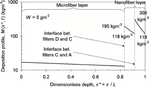
Filter G is also an inhomogeneous dual-layer filter, but its nanofiber layer has a gradient packing density by stacking the more porous (also more permeable) filter C upstream to the less porous filter A. As depicted in , although the pressure drop across filter G (53.96 Pa) is higher than filter E (44.13 Pa) at clean stage, filter G has a lower rate of increase in pressure drop. Under 5 gm− 2 deposit, the pressure drop across filters E and G are 356 and 289 Pa, respectively, and their difference grows with deposit mass. shows the deposition profile across filter G when W equals to 5 gm− 2. Compare with , the deposition profile across nanofiber layers of filter G is more uniform than that of filter E. It is because the nanofiber layer in filter G has a gradient packing density, using the side with higher porosity to accommodate the densely packed deposit at face region, while leaving the side with lower porosity to handle the tail region of deposition profile. This relieves the skin effect as observed in single nanofiber filter.
Regeneration of Nanofiber Filter
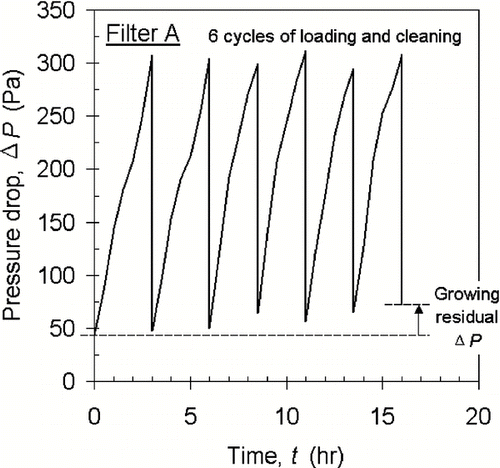
Our preliminary study shows that nanofiber filter A loaded with sub-micron NaCl aerosol can be cleaned by pulsating air jet blowing from filter downstream side. The alternative loading and cleaning cycles are shown in . The slow growing residual pressure drop reflects there remains small residual deposit in the filter.
CONCLUSIONS
The first part of our study has demonstrated that the higher fractional efficiency and quality factor of nanofiber filter does not necessarily imply that it is “absolutely” better than microfiber filter. Microfiber filter has higher dust holding capacity under continuous loading of sub-micron aerosol, as justified from its much lower pressure drop increase rate than nanofiber filter. In order to compensate for each other's shortcoming, a composite (filter E) formed by placing microfiber filter (filter D) upstream and nanofiber filter (filter A) downstream is proposed. Loading test results show that filter E has lower pressure drop increase rate than its control sample filter F, first of all because the upstream microfiber layer in filter E has collected part of the challenging aerosol (despite they may be sub-micron in size), thus reduces the loading on downstream nanofiber layer. Secondly, the deposition profile in nanofiber layer of filter E is more uniform than that of filter F (reducing the skin-layer effect), thus its pressure drop increase rate is suppressed significantly. Thirdly, filter F has nanofibers placed immediately before microfibers and they are unobstructed for collecting aerosol in contrast to the reverse arrangement. Hence, a major portion of aerosol collected by filter F is in its nanofiber layer. The nanofiber layer downstream of the microfiber layer can be further improved by having a gradient of fiber packing density from small to large density towards downstream. This provides a transition from the more porous microfiber to the more densely packed nanofiber, which is favorable in redistribution of deposit in the dual-layer filter translating to even lower pressure drop and effectively mitigating the skin effect. Our findings suggested that the inhomogeneous dual-layer filter is effective to relieve clogging or skin formation of nanofiber filter by providing better capacity utilization. On the other hand, nanofiber enhances sub-micron aerosol capture, rendering our proposed dual-layer filter suitable to extend operation from clean to loaded stage. Also initial tests on backpulsing of nanofiber filter shows that the filter can be effectively cleaned periodically of sub-micron aerosol deposit and such process can be integrated into the operation of the filter.
REFERENCES
- Brown , R. C. and Wake , D. 1999 . Loading Filters with Monodisperse Aerosols: Macroscopic Treatment . J. Aerosol Sci. , 30 : 227 – 234 .
- Callé , S. , Bémer , D. , Thomas , D. , Contal , P. and Leclerc , D. 2001 . Changes in the Performances of Filter Media During Clogging and Cleaning Cycles . The Annals of Occupational Hygiene , 45 : 115 – 121 .
- Gradoń , L. , Podgórski , A. and Bałazy , A. Proceedings of FILTECH EUROPA 2005 . pp. II – 178 . Wiesbadan, , Germany : VDI .
- Lee , J. K. , Ahn , Y. C. , Park , S. K. , Kim , G. T. , Hwang , Y. H. , Lee , C. G. and Shin , H. S. 2006 . Development of High Efficiency Nanofilters Made of Nanofibers . Current Applied Physics , 6 : 1030 – 1035 .
- Leung Wallace , W. F. and Hung , C. H. 2008 . Investigation on Pressure Drop Evolution of Fibrous Filter Operating in Aerodynamic Slip Regime Under Continuous Loading of Sub-Micron Aerosols . Separation and Purification Technol. , 63 : 691 – 700 .
- Pich , J. 1966 . “ Aerosol Science ” . In Theory of Aerosol Filtration by Fibrous and Membrane Filters , Edited by: Davies , C. N. 223 – 283 . London : Academic Press .
- Podgórski , A. 1998 . Macroscopic Model of Two-Stage Aerosol Filtration in a Fibrous Filter Without Reemission of Deposits . J. Aerosol Sci. , 29 : S929 – S930 .
- Podgórski , A. , Bałazy , A. and Gradoń , L. 2006 . Application of Nanofibers to Improve the Filtration Efficiency of the Most Penetrating Aerosol Particles in Fibrous Filters . Chemical Engineering Sci. , 61 : 6804 – 6815 .
- Podgórski , A. 2009 . Estimation of the Upper Limit of Aerosol Nanoparticles Penetration Through Inhomogeneous Fibrous Filters . J. Nanoparticle Res. , 11 : 197 – 207 .
- Przekop , R. and Gradoń , L. 2008 . Deposition and Filtration of Nanoparticles in the Composites of Nano- and Microsized Fibers . Aerosol Sci. Technol. , 42 : 483 – 493 .
- Sakano , T. , Otani , Y. , Namiki , N. and Emi , H. 2000 . Particle Collection of Medium Performance Air Filters Consisting of Binary Fibers Under Dust Loaded Conditions . Separation and Purification Technol. , 19 : 145 – 152 .
- Tsai , Peter P. , Schreuder-Gibson , H. and Gibson , P. 2002 . Different Electrostatic Methods for Making Electret Filters . J. Electrostatics , 54 : 333 – 341 .
