Abstract
This work examines the measurement of surface specific soot oxidation rates with the High Temperature Oxidation-Tandem Differential Mobility Analyzer (HTO-TDMA) method. The Computational Fluid Dynamics package CFD-ACE+ is used to understand particle flow, oxidation and size dependent particle losses in the laminar aerosol flow reactor using an Eulerian-Lagrangian framework. Decrease of DMA selected mono-disperse particle size distribution due to oxidation within the aerosol tube is modeled using fitted kinetic soot oxidation parameters. The effects of Brownian diffusion and thermophoresis on particle flow and loss to the reactor walls are evaluated. The position of peak particle diameter, which is used as an indicator to determine oxidation rate, is found to be independent of diffusion, thermophoresis and secondary flow effects, thus validating its use in deriving kinetic soot oxidation parameters. Diffusion does not affect the evolution of particle size distribution within the reactor. However, thermophoresis is found to be the dominant mechanism influencing both shape of particle size distribution and particle loss to the walls of the aerosol reactor. Simulations show reduced effects of secondary recirculating flows on the particle flow trajectories in a vertical furnace as compared to horizontal furnace orientation. This work highlights the importance of making accurate measurements of temperature within the modeling domain. Since gas temperature within the flow tube could not be measured with high radial resolution using radiation shielded thermocouple, the derived soot oxidation rate may be uncertain by a factor of 2. Importantly, CFD simulations suggest that a distribution of temperature and size-dependent particle reactivities may be present in the reactor, requiring further theoretical and experimental investigation.
1. INTRODUCTION
Laminar flow tubular reactor has been widely used to measure physical and chemical characteristics of particles. CitationSakurai et al. (2003) measured volatility of diesel particles by evaporating semi-volatile components of particles in the flow reactor at temperatures ranging 30–450°C using nano-Tandem Differential Mobility Analyzer (TDMA) and a flow reactor. CitationBilde and Pandis (2001) measured evaporation rates and vapor pressures of individual organic aerosol species with varying residence times and temperature in the laminar flow tube. CitationMcMurry et al. (1983) measured the reaction rates between ammonia gas and sulfuric acid aerosols by measuring hygroscopic and deliquescent properties of the product aerosols, while CitationFranz et al. (2000) looked at effects of addition of H2O2 on diesel soot particles using a thermolysis tube and TDMA. CitationKhalizov et al. (2006) developed and characterized a laminar aerosol flow reactor to study ice nucleation, deliquescence and efflorescence in model atmospheric aerosols in the temperature ranges of 240–300 K. CitationHiggins et al. (2002) measured soot oxidation rate using the reactor and TDMA at temperatures ranging 500–1100°C. Considering the diverse applications of the laminar flow reactor, it is important to thoroughly understand particle phenomena within the reactor.
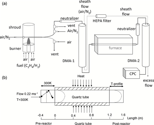
In many applications the flow reactor was used along with Tandem Differential Mobility Analyzer (TDMA) as shown in . Size selected aerosol stream from the first DMA is subject to various reaction conditions such as temperature and oxidant concentrations in a laminar flow reactor. The second DMA following the reactor measures changes in particle size and concentration. Particle size distribution changes due to chemical and physical transformations in the flow reactor. These transformations are function of particle size, shape, particle surface characteristics, reaction conditions, and reactor geometry. Physical and chemical properties of particles such as hygroscopicity, volatility and oxidation rate are determined by comparing particle size distributions at the inlet and outlet of the flow reactor. When reaction conditions are not strongly size dependent, one can simply compare peak particle diameter (mode of the size distribution) change to determine particle properties of interest. On the other hand, when reaction conditions are strongly size-dependent one needs to understand and characterize particle behavior better in the flow reactor taking into account size dependent phenomenon such as particle losses to the wall. In addition, particles move radially and axially within the reactor due to diffusion (CitationGomes et al. 1993) and thermophoresis (CitationTalbot et al. 1980).
FIG. 1 (a) Schematic diagram of the TDMA system measuring soot oxidation rate (CitationHiggins et al. 2002). (b) Schematic showing the modeling domain in CFD-ACE+. Flow enters a pre-reactor section at 0.22 ms− 1 and 300 K. Both the furnace and post-reactor have a parabolic velocity profile, while the pre-reactor has plug flow as shown by the dotted lines. Axial length (m) scale in the z direction along the modeling domain is also shown.
For high temperature applications such as soot oxidation studies (CitationHiggins et al. 2002), particle size distribution changes within the reactor as function of flow profile and temperature. Particle trajectories are complex due to secondary flow being associated with relative magnitudes of buoyancy and momentum at high temperatures. Ultrafine particles (diameter D p < 100 nm) relax fast to changing flow conditions; however, diffusion coefficient increases with decreasing particle size causing greater loss of smaller particles to the walls. When reactor walls are cold compared to gas flow, thermophoretic particle deposition to the wall becomes important. Thermophoresis is a weak function of particle size for ultrafine particles. Numerical simulations on particle transformation in the thermophoretic cell (1.2 cm o.d. × 0.04 cm i.d., total flow of 16 lpm at 500°C) with SiO2 aerosols suggested little influence of Brownian diffusion for particle sizes greater than 0.01 μm while thermophoretic losses could be greater than 50% depending upon thermal gradients and particle residence time within the flow tube (CitationChang et al. 1990). Those simulations were designed to understand thermophoretic losses in the production of ceramics in aerosol processes (CitationChang et al. 1990).
CitationHiggins et al. (2002) developed a new method to study kinetics of soot oxidation by air using a high temperature oxidation-tandem differential mobility analyzer (HTO-TDMA). The method has been widely applied to measure kinetics of soot oxidation (CitationHiggins et al. 2002; CitationHiggins et al. 2003; CitationKim et al. 2005; CitationNienow et al. 2005) as well as various nano-particle oxidation reactions (CitationHolm and Roberts 2007; CitationZhou et al. 2008). The HTO-TDMA method can measure intrinsic reaction rate of particles, as particle reaction is decoupled from mass and heat transfer effects in contrast to bulk methods such as Thermo-Gravimetric analysis (TGA). CitationHiggins et al. (2002) studied soot oxidation rates for 3 different mono-disperse particle sizes: 40, 90, and 130 nm in the presence of air in a high temperature tube flow reactor. They observed an increasing broadening of particle size distribution with the mode shifting to lower particle sizes at higher temperatures (see of CitationHiggins et al. (2002)). The position of the mode became less visible at higher temperatures due to the increasing tail of smaller particle size (size-distribution broadening), limiting application of flow reactor at higher temperatures. Major assumptions made by CitationHiggins et al. (2002) were fully developed laminar velocity profile in the reactor ignoring buoyancy effects, and size dependent particle losses within the furnace do not change the peak diameter position.
Accurate analysis of the HTO-TDMA results requires a thorough understanding of various particle size-dependent phenomena in the reactor. In addition to diffusion and thermophoresis, particles may show a distribution of kinetic reactivities as suggested by the carbon burnout model for coal particles (CitationHurt et al. 1998). Understanding the distribution of kinetic reactivities of particles requires that other size-dependent particle phenomena such as diffusion and thermophoretic effects in the reactor be accurately resolved.
This study evaluates the experiments by CitationHiggins et al. (2002) studying soot oxidation from an ethylene diffusion flame. In addition to studying kinetics of soot oxidation, the goal of this study is to improve understanding of HTO-TDMA method which is used in a variety of applications as discussed earlier. This work simulates oxidation of mono-disperse soot particles in the laminar flow reactor in the temperature range of 500 to 950°C using the Computational Fluid Dynamics package CFD-ACE+. An Eulerian-Lagrangian framework is used to model particle flow, oxidation and loss due to Brownian diffusion and thermophoresis. Flow and temperature profile within the tube reactor are solved using the Eulerian approach, while particle transport, oxidation and loss are modeled using the Lagrangian approach. First, various modules including Brownian diffusion and thermophoresis in CFD-ACE+ are validated with experimental data from other studies and theoretical predictions. Then model results are compared to experimental data and the validity of the assumptions made by CitationHiggins et al. (2002) in fitting kinetic soot oxidation parameters are discussed. This work also examines the assumptions of laminar fully developed flow, uncertainties associated with neglecting effects of buoyancy induced secondary recirculation flow, and influence of diffusion and thermophoretic losses to the resulting particle size distribution at the outlet of the furnace. In addition, the uncertainties associated with the HTO-TDMA method are examined and ways to reduce uncertainty and increase the sensitivity of the method (in terms of distinct peak diameter) for high temperature applications are addressed.
2. EXPERIMENTAL METHOD OF PREVIOUS STUDY
The details of experimental apparatus and measurement have been described in CitationHiggins et al. (2002), however, a brief description follows. Poly-disperse soot particles were generated in an ethylene diffusion flame and then sent to a differential mobility analyzer for size selection. Size-selected mono-disperse soot particles from the first DMA were then oxidized in a high temperature flow reactor and the resulting particle size distribution was measured using a second DMA with a condensation particle counter (CPC) as a detector. Size distributions from the DMA were corrected for charging efficiency, and penetration efficiencies of the CPC and DMA. Their results for kinetic soot oxidation parameters showed good agreement with previous studies employing a wide range of materials and techniques to measure soot oxidation rates.
CitationHiggins et al. (2002) fitted kinetic parameters in terms of observed decrease of soot particle size by oxidation using a non-linear least squares fit to experimental data. Decrease in particle diameter was described using a modified form of Arrhenius expression given as:
3. MODELING
3.1. Tube Geometry and Boundary Conditions
Monodisperse soot particles passed through a quartz flow tube of 1.0 cm i.d. (1.2 cm o.d.) × 120 cm in length suspended at the centre of a 2.5 cm i.d. aluminum oxide tube placed in a tube furnace (Lindberg model 55122 with 58114 temperature control) as described by CitationHiggins et al. (2002). This arrangement reduces hot spots in the flow tube which may be caused by uneven furnace heating elements or by contact between aluminum oxide and quartz tubes. The furnace was 50 cm long with a heated length of 30 cm. Gas temperature within the central 40 cm length of the quartz tube was measured using a K-type thermocouple (Omega). Measurements were made with the thermocouple junction exposed and with it shielded to assess the effects of radiative heat transfer. It was assumed that the shielded thermocouple measured the gas temperature, while the non-shielded thermocouple junction measured the wall temperature due to radiative heat transfer. Measurements made at 1000°C showed no difference between shielded and exposed thermocouple tips suggesting that gas and wall temperatures were the same within the heated length of the quartz tube. Also temperatures were found to be radially uniform within the quartz tube (CitationHiggins et al. 2002). However, with the radiation shield in place, resolution of radial temperature measurement is limited as outer diameter of the shielded thermocouple was about half the inner diameter of the quartz tube in this study. Hence temperature near the tube wall, where highest temperature gradients may exist, could not be measured accurately. Also, it's not clear whether the single-shielded thermocouple measured the correct gas temperature. A double-shielded thermocouple may have given more confidence in their measurement but there is no commercially available double shielded thermocouple in small size. In addition, the outer heated aluminum oxide tube extended for about 5 cm on both sides of the measurement zone increasing the quartz tube wall temperatures above ambient temperature beyond the heated zone. No temperature measurements are available in these sections. This introduces uncertainty in modeling the flow characteristics within the tube. In addition, heated air and soot may participate in absorption and emission of infrared radiation within the quartz tube. A calculation suggested that absorption of infrared radiation by the CO2 and H2O present in the air flowing through the furnace would not significantly affect the radiative heat exchange in the furnace. The Planck mean absorption coefficient for CO2 is 4 to 5 times higher than H2O in the temperature range 1100–2300 K (CitationFuss and Hamins 2002). Either of CO2 and H2O concentrations would be significantly lower in the tube as compared to flame conditions due to dilution (factor of ∼200) in the ejector diluter and in the first DMA. Also soot volume fraction in the tube is too low (maximum value of 1· 10−11 m3 m−3 for 130 nm particles) to affect the radiation heat exchange significantly. If soot volume fractions exceed 1· 10−7 m3 m− 3, soot begins playing a major role in radiative heat exchange at longer wavelengths (CitationViskanta and Menguc 1987).
In this work, particle transport and oxidation within the quartz tube are simulated using the Computational Fluid Dynamics software CFD-ACE+. Particle transport modeling requires accurate boundary conditions for flow field and temperature profile within the flow tube. When buoyant forces induced by temperature differences are significant as compared to inertial forces, i.e., the ratio of Grashof Number to square of Reynolds number is greater than 1, particles can follow complex trajectories within the furnace. In this work, the ratio of Grashof Number to square of Reynolds number was less than 1 at all furnace set-point temperatures above 500°C. Thus buoyancy forces were not dominant within the current system. Hence, flow within the tube is modeled as laminar, allowing for secondary flow in the heated zone of the furnace. All simulations are performed with a convergence criteria of 1 · 10− 4, i.e., until the residuals for all solved variables reduced by at least four orders of magnitude. It is also ensured that the mass and energy imbalances are less than 1%.
Soot oxidation is modeled using the fitted kinetic parameters A nm and E a . During the first set of model simulations, axial temperature measurements made by CitationHiggins et al. (2002) within the quartz tube are applied as wall temperature boundary conditions, while fluid flow is modeled assuming convective heat transfer from the heated quartz tube wall to the fluid. These simulations are referred to as the “Case 1.” A schematic of the modeling domain is shown in while shows the configuration of the gridded modeling domain for CFD simulations. Grid spacing within the domain is chosen after carefully evaluating different grid resolutions with respect to temperature, flow and particle penetration efficiencies as described in the following section. The inlet fluid flow velocity at room temperature is fixed at 0.22 ms− 1 corresponding to a flow rate of 1 l min− 1. Wall temperatures are assumed to be at 27°C at the upstream of the heated zone; while temperatures at the downstream of the heated zone are estimated from temperature measurements inside another identical furnace. Sudden temperature jump is allowed at the axial location z = 0.4 m () where the cooler fluid at 27°C comes in direct contact with the heated furnace (500–600°C) as shown in and . This is an extreme entrance step temperature of 300°C giving maximum strength of secondary flows ( and ) which could be generated in the quartz tube. This condition allows us to investigate the influence of buoyancy induced secondary flows on evolving particle size distribution within the reactor. Reducing this entrance temperature step caused lower particle losses (not shown) however, relative shape of the particle size distribution did not change significantly as compared to the extreme entrance temperature step of 300°C. Errors in temperature profile measurements at the downstream of the heated zone (beyond z = 0.8 m in ) were not found to affect the results significantly. CFD simulations suggest radial temperature gradients of 100°C over 0.5 cm radial distance within the hottest zone in the furnace at furnace set-point temperature of 950°C. Temperature is lowest in the centre of the furnace increasing towards the walls. In contrast, the measurements suggested radially uniform temperature profiles throughout the furnace. As mentioned earlier, the measurements may have suffered from loss in radial temperature resolution in case of the shielded thermocouple tip.
FIG. 2 Grid configuration applied to the simulated geometry in CFD-ACE+. The axial direction is scaled by a factor of 0.01 to make the circular cross section more visible.
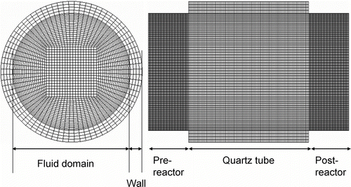
FIG. 3 Iso-contours of temperature and axial velocity for “Case 1” (above) and “Case 2” (below) at the centre of the tube. The axial direction is scaled by a factor of 0.01.
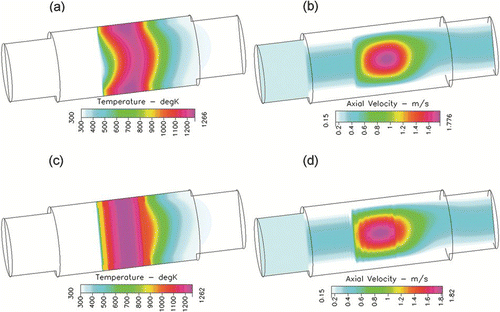
In order to be consistent with the fitted soot oxidation kinetic parameters which assumed radially uniform temperature profile within the furnace, a second set of CFD simulations are performed. The heated zone within the furnace is split into 8 equal volumes including the gas and quartz tube wall domains. Temperatures are forced to be radially and axially uniform within each of these domains, and are set to average temperature measured within each domain, by introducing volumetric heat sources. Wall temperatures at the upstream and downstream of the heated zone are treated similar to the “Case 1.” For discussion purposes these simulations with forced uniform temperature profile in the heated zone are referred to as “Case 2.” Thus “Case 1” and “Case 2” simulations represent two extremes in application of temperature gradients within the system. Comparing the decrease in particle size due to soot oxidation between these 2 sets of simulations helps us evaluate the uncertainties in fitted soot oxidation kinetic constants. shows the velocity and temperature profiles within the modeled geometry at furnace set-point temperature of 950°C for the two cases. As shown in , the “Case 1” simulation shows temperature changing radially inside the furnace while “Case 2” has radially uniform temperature profile in the heated section of the furnace (). Gas velocity increases with increasing temperature in the axial direction due to decrease in density (ideal gas law) to satisfy mass conservation ( and ). Thus the central portion of the tube having highest temperatures within the domain shows highest axial velocity.
3.2. Particle Simulation
3.2.1. Evaluation of Brownian Diffusion Module
Particle transport within the model is solved using the Spray module in CFD-ACE+. The particle transport model adopts the Lagrangian approach that solves the equations of mass and momentum transport for particles. The momentum transport equation includes forces to take into account thermophoresis and Brownian diffusion. The velocity, position, and temperature of the particles are calculated by integrating the transport equations over a time-step small enough such that there are tolerably small changes in the external force field (CitationGupta 1986). To ensure proper application of the commercial CFD codes to study particle behavior, extensive validation studies are required. For example, CitationSong and Dhaniyala (2007) highlighted issues with application of commercial code FLUENT in calculations of particle standard deviations under Brownian diffusion. Two sets of validation studies are performed to evaluate the Brownian diffusion module within CFD-ACE+: (1) Validation of standard deviations of mass-less Brownian particle, and (2) Penetration efficiency in tubes of different lengths and diameters for various particle sizes. In both the validation studies, described in detail below, integration time-steps are varied between 10− 3 to 10− 7 s. Numerical results were found to be in excellent agreement with theory for particle time steps of 10− 4 to 10− 7 s; hence particle time steps of 10− 5 s are used for all future simulations. In addition, two different geometric configurations are used for this evaluation: rectangular channel and 3D flow tube. Rectangular channel geometry has uniform grid size, however for the 3D flow tube, with uniformly spaced grids in the angular direction, the grid volumes increase radially towards the tube wall. The grids used for the 3D flow tube are shown in . Based on several studies with different coarse and fine grids, the grid configuration shown in is selected for the circular geometry. In the axial and radial directions, 1.7 grids cm− 1 and 40 grids cm− 1, respectively, are used; while in the circumferential direction 25 grids cm− 1 are used. Coarser grids are applied in the tube wall domain as compared to the fluid flow domain.
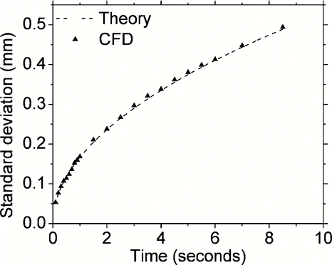
Validation of standard deviations of mass-less Brownian particles: Standard deviations of Brownian displacement of 5000 particle trajectories in each of the two radial directions (X and Y direction) are evaluated against the Stokes-Einstein's equation given as:
FIG. 4 Comparison of predicted standard deviations of 5000 particle trajectories of 20 nm particles in the radial Y direction as a function of elapsed time after particle injection in the modeling domain. Theoretical predictions shown by the dotted line used the Stokes-Einstein relation as discussed in the text.
Validation of penetration efficiencies: Overall particle penetration efficiencies due to convective diffusion at different inlet flow and temperature conditions are evaluated against theoretical expressions of particle penetration efficiency (CitationGormley 1949) and an independent Eulerian approach. The Eulerian approach injects a gas tracer within the geometry with gas diffusion coefficient equal to diffusion coefficient of particle sizes of interest. When the tracer diffuses to the boundary of the geometry, it is lost by reaction, similar to wall loss of particles due to diffusion. Thus overall penetration efficiency of the tracer provides another independent measure of expected particle penetration efficiency in any given geometry. Theoretical expressions for particle penetration efficiency in rectangular and circular tube geometries show excellent agreement with the Eulerian tracer gas approach. In this study, the Lagrangian particle penetration efficiencies are validated against the Eulerian predictions as shown in .
TABLE 1 Comparison of particle penetration efficiencies for 2500 particles of 10 nm diameter with and without pre-reactor
To ensure a uniform particle concentration per unit grid surface area at the inlet of the flow tube, progressively more particles are injected in the radially outward direction as grid sizes are bigger near the walls. For the rectangular geometry, the injected particles are uniformly spaced from the center to the wall. Initial particle velocities are assumed to be zero in the X, Y, and Z directions. However, since the ultrafine-particles relax fast to the flow conditions, initial particle velocities do not affect particle penetration efficiencies. The effects of grid spacing and geometry on overall particle penetration efficiency are evaluated by comparing CFD predictions with theory. shows overall particle penetration efficiencies for the rectangular channel geometry and 3D circular geometry at different conditions of inlet fluid velocity and channel lengths. The Lagrangian particle penetration efficiencies are also compared to Eulerian simulations using the tracer approach. The particle penetrations at different inlet fluid velocities are evaluated for 2 different flow regimes: plug flow and parabolic flow. Lagrangian particle penetration efficiencies for the plug flow case agree with Eulerian simulations within 3%. However, for the parabolic flow the Lagrangian efficiencies are 10–15% lower as compared to Eulerian simulations. This could occur if particle injections within the channel are not sufficiently randomized. To account for this, a 0.4 m pre-reactor section with plug flow, corresponding to a particle residence time of 1.6 seconds, is placed before the actual modeling domain. This section is labeled as negative 0.4 m to 0 m as shown in . Particles are injected 0.05 m downstream of the inlet (–0.35 m in ) to minimize entrance effects, and are allowed to re-distribute randomly with Brownian motion inside the pre-reactor with specular reflection at the walls preventing any particle losses to walls. This arrangement also allows the particle velocities to be weighted by the axial fluid velocity in the plug flow pre-reactor section. Adding the pre-reactor before the modeling domain improved particle penetration efficiencies bringing predictions closer to Eulerian simulations for the parabolic profile in both the rectangular and 3D tube geometry within 2% as shown in . For all future simulations, a pre-reactor length of 0.4 m was added before the inlet of the modeling domain to initialize particle positions and velocities before they entered the quartz tube inside the furnace extending from 0 to 1.2 m as shown in . The entire modeling domain consists of a 0.4 m pre-reactor with plug flow and specular reflection of particles at the tube walls as discussed, a 1.2 m long quartz tube section with specified flow and temperature boundary conditions (“Case 1” and “Case 2” simulations), and a 0.4 m post-reactor section to account for tubing connecting the furnace to the second DMA as shown in .
3.2.2. Evaluation of Thermophoretic Module
The thermophoretic module within CFD-ACE+ is evaluated by comparing measured thermophoretic deposition efficiency (CitationTsai et al. 2004) with CFD predictions. For a self consistent evaluation of the CFD thermophoretic solver, the same flow tube (0.43 cm i.d. × 1.18 m length), laminar flow conditions (Re = 1340) and inlet gas temperatures (343 and 373 K) are used as discussed by CitationTsai et al. (2004). In addition the thermophoretic solver is also evaluated at higher temperatures (500 and 850°C) using a simple theoretical expression for a long tube (gas temperature approaches that of tube wall at the exit) which relates thermophoretic deposition (L t ) to gas outlet and inlet temperatures (CitationQiang Wei & Watts 2001) (T out and T in , respectively) given as:
3.2.3. Particle Injection for Comparison to Measurements
During HTO-TDMA experiment, size selected monodisperse particles were sent to the high temperature flow reactor where particles were oxidized in flight. The second DMA following the flow reactor measured change in particle size distribution to determine kinetics of soot oxidation. DMA selected monodisperse distribution consists of particle concentrations distributed within a narrow range of sizes with peak concentrations at the selected size (see 500°C case in ). The particle size distribution coming out of the first DMA could be thought of as an input particle function, while size distribution measured by second DMA after the furnace would be the corresponding output particle function. The goal of CFD simulations is to predict the output particle function, and investigate effects of diffusion, thermophoresis and other unaccounted particle phenomena such as reactivity distribution on resulting size distribution. If the particle transformation within the furnace were simulated correctly, CFD should predict the particle size distribution measured by the second DMA (output particle function) for any given input particle function.
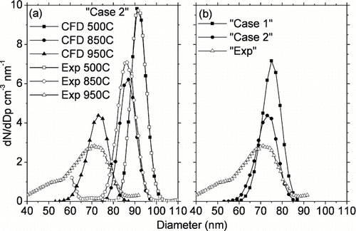
FIG. 5 Comparison of CFD predictions against measured outlet particle size distribution for (a) “Case 2” at various temperatures (b) “Case 1” and “Case 2” at furnace set-point temperature of 950°C. Both the cases fail to predict the long tail towards smaller particle sizes at 950°C as shown in (b).
Measurement of input particle function requires measuring the size distribution of monodisperse particle stream coming out of the first DMA. Direct measurements of input particle function (in other words measurement upstream of the furnace and downstream of the 1 st DMA) is not available (CitationHiggins et al. 2002). However, output particle function can be assumed to be similar to input particle function when the furnace was turned off, i.e., at ambient temperature. This was verified by CFD simulations showing that thermophoresis and diffusion loss at this condition is negligible (data not shown).
In addition, CitationHiggins et al. (2002) found very little changes in measured particle size distribution with the furnace operating between room temperature and 500°C. This was because diffusion, oxidation rate and thermophoretic particle losses are minimal at 500°C for ultrafine particles above 10 nm. However, the peak particle diameter shifted by about 1nm due to evaporation/thermal restructuring of particles. In this work, the small decrease in particle size due to evaporation is not simulated. Hence, the size distribution measured with the HTO-TDMA at furnace set-point temperature of 500°C is used as input particle function for the simulations. In order to simulate the input particle function using the Lagrangian approach and to achieve statistically significant results, 50,000 particles are introduced in the modeling domain for each simulation. These particles are distributed in size bins to correspond to the input particle function, and the particles in each size bin are then injected uniformly across the 1 cm i.d. tube cross section. Particles coming out of the modeling domain are counted in size intervals of 2 nm starting from zero to the maximum particle size injected in the domain. These particle counts are scaled by a uniform factor for each simulation to compare them with measured particle concentrations. In order to convert the scaled particle counts to size distribution function (dN/dD p cm− 3 nm− 1), these counts are divided by the bin size (2 nm). The constant scaling factor is calculated as ratio of total number of particles measured using HTO-TDMA at 500°C (CitationHiggins et al. 2002) to CFD predicted total number of particle coming out of the modeling domain at 500°C. Thus CFD predictions at 500°C are overlapped exactly on top of TDMA measurements at 500°C as shown in , and the same constant scaling factor is used for all temperatures higher than 500°C. This scaling allows a direct comparison of CFD predictions and measured particle size distributions at all temperatures higher than 500°C. If CFD simulations predicted experimental measurements accurately, i.e., all size-dependent particle phenomena were accurately accounted, the scaled particle counts at the outlet of the modeling domain should lie exactly on top of measured particle size distributions at all furnace set-point temperatures higher than 500°C. In the following section the CFD simulations are compared to experimental data.
4. RESULTS
In this section, effects of each of the model parameters: boundary conditions, kinetic oxidation parameters, particle loss due to Brownian diffusion and thermophoresis, and buoyancy induced recirculation effects are evaluated. Effects of uncertainties in temperature profile measurements on evolution of particle size distribution are evaluated by comparison of “Case 1” and “Case 2” simulations covering the two extreme temperature boundary conditions. In addition, effects of Brownian diffusion and thermophoresis are independently evaluated by “turning off” each of these processes in the simulations. Particle motion by thermophoresis is also affected by errors in temperature profile measurements, hence a combination of “Case 1” and “Case 2” simulations with thermophoresis turned “on” and “off” spans the uncertainties in modeling conditions. Effects of buoyancy induced recirculation are investigated with practical application of horizontal vs. vertical furnace orientation. This analysis helps us understand the uncertainties in modeling soot oxidation through the HTO-TDMA method.
4.1. Boundary Conditions and Kinetic Constants
shows model predictions as compared to measurements for initial particle size of 90 nm. Results from the “Case 2” simulations using the kinetic oxidation parameters derived by CitationHiggins et al. (2002) are used for comparison to experimental data. As mentioned earlier particle counts in each size bin are scaled with respect to experimental data at 500°C and divided by the bin interval size, so predicted particle size distribution lies exactly on top of measurements at 500 °C. shows that peak diameter of particle size distributions measured at 850°C and 950°C furnace set-point temperatures are well predicted by CFD. Also total particle penetrations are well predicted by CFD (within 10% of measurements) at both 850°C and 950°C. At 850°C predicted peak particle concentrations agree within 10% with experimental data, however, CFD over-predicts peak particle concentrations by 70% at 950°C. This discrepancy between model and measurements results from experimental data showing an increasing “broadening effect” resulting in loss of sensitivity in terms of position of the peak diameter at higher temperatures above 850°C. The “broadening effect” refers to particle size distributions becoming increasingly poly-disperse extending to smaller particle sizes as compared to CFD simulations. compares results from “Case 1” and “Case 2” simulations against measurements at furnace set-point temperature of 950°C. As described earlier, “Case 1” and “Case 2” simulations represent two extremes on the application of temperature gradients in the system. For “Case 1,” the reduction in peak diameter was initially under-predicted (not shown) using the kinetic oxidation parameters derived by CitationHiggins et al. (2002). In order to correctly predict the measured peak diameters, the kinetic parameter (frequency factor, A 93 in (CitationHiggins et al. (2002) had to be increased by a factor of 1.8 (E A was fixed at 164 kJ mol− 1) resulting in the distribution shown in . This result suggests that the fitted frequency factor may be uncertain by a factor of 2 due to uncertainties in temperature measurement within the flow tube. This uncertainty can be reduced by better measuring wall temperature profile or radial gas temperature profile using small thermocouple with multiple radiation shields. As shown in , “Case 2” simulations have higher particle loss resulting in 30% lower particle penetrations as compared to the “Case 1.” However, both “Case 1” and “Case 2” simulations fail to explain the broadening of particle size distribution at high temperature of 950°C. In addition to 90 nm particles, CFD predictions for particles of initial sizes 40 nm and 130 nm (not shown) were also compared with experimental data from CitationHiggins et al. (2002). These comparisons showed the same increased “unexplained broadening effect” of particle size distribution with increasing furnace temperatures as compared to simulations. compares CFD predictions with experimental data for particles of initial size 40 nm at furnace set-point temperature of 950°C, and will be discussed in the following section.
FIG. 6 Effects of modeling parameters for “Case 2” simulations on predicted particle size distribution at the outlet of the reactor at a furnace set-point temperature of 950°C. (a) Thermophoresis with 90 nm initial size particles. (b) Diffusion with 90 nm initial size particles. (c) Thermophoresis and diffusion for 40 nm initial size particles. “Th+Diff”: Both thermophoresis and diffusion turned on, “NoTh+Diff”: Thermophoresis turned off but diffusion turned on, “Th+NoDiff”: Thermophoresis turned on but diffusion turned off, “Exp”. Measured size distributions from (CitationHiggins et al. 2002).
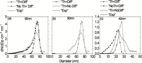
Particles are continuously redistributed and lost to the walls of the tube due to random Brownian motion and thermophoretic movement in the direction of temperature gradient. Brownian diffusion is strongly size dependent while thermophoresis is size independent for nanometer sized particles in this study. In order to evaluate the independent effects of Brownian diffusion and thermophoretic losses on evolution of particle size distribution within the reactor, the model was run by turning off diffusion and thermophoresis independently for both “Case 1” and “Case 2” simulations. For ease of discussions, since “Case 2” simulations used the same kinetic oxidation parameters derived by CitationHiggins et al. (2002), the modeling results are discussed in terms of “Case 2” simulations. For particles of initial size 90 nm, the shape of the broadening particle size distributions at higher temperatures appears to be better reproduced by turning off thermophoretic particle (“no thermophoresis case”) losses in the simulations (). However, these simulations with thermophoresis turned off over-predict total particle penetration by 30% as compared to measurements at 950°C. shows simulation results for particles of initial size 40 nm. Turning off thermophoresis causes the peak particle diameter to decrease from 27 to 23 nm, in better agreement with measurements. Also total particle penetrations are well predicted with “no thermophoresis” for particles of initial size 40 nm. However, simulations with “no thermophoresis” for both 90 nm and 40 nm initial sized particles suggest an extended tail of even smaller particle sizes as compared to measurements. Thus excluding thermophoretic losses leads to greater discrepancies from the measurements. In contrast, simulations with diffusion turned off show no significant difference in particle size distributions at the outlet for both 90 nm and 40 nm initial size particles ( and , respectively). Thus Brownian diffusion does not affect evolution of particle size distribution within the reactor until furnace set-point temperatures of 950°C. With increasing furnace temperatures, the residence time of particles in the furnace is reduced due to increasing gas velocities, offsetting the increase of particle diffusion to the wall. In this work, the extending long tail of particle size distributions towards smaller particle sizes for both particles of initial size 90 nm and 40 nm (“broadening effect”) measured at higher furnace temperatures could not be explained by diffusion and thermophoretic effects for both “Case 1” (not shown) and “Case 2” simulations. In addition, particles of initial size 40 nm showed a longer tail towards larger particle sizes not explained by CFD simulations as shown in . Assuming that these simulations cover the range of uncertainties in application of temperature profiles within the reactor, the unexplained discrepancies could be attributed to another phenomenon which could not be implemented in CitationHiggins et al. (2002) simple Arrhenius model. This phenomenon most likely could be attributed to some reactivity distribution of particles such as in the CBK (carbon burnout model) (CitationHurt et al. 1998). The CFD simulations sorted out influence of diffusion and thermophoresis considering the range of uncertainties due to errors in measurement of temperature profiles. These simulations give more confidence that this broadening means another physical phenomenon as just mentioned.
Particle penetrations and residence times within the furnace are also affected by secondary flows. Similarly recirculation and local turbulence effects could arise from mixing of gas flows flowing through a non-uniform temperature furnace. Changing particle residence times could change decrease of particle diameter due to oxidation within the furnace. Recirculation effects are expected to be lower in cases when buoyancy forces act in the direction of flow, i.e., vertical tube configuration with flow moving upwards as it is heated or flow moving downwards as it is cooled, as compared to horizontal flow tube configurations (CitationKhalizov et al. 2006). However, in this work, the furnace of interest has an axial temperature profile which is close to parabolic with maximum temperature in the centre of the heated zone (CitationHiggins et al. 2002). In the following section effects of furnace orientation on outlet particle size distribution are evaluated.
4.2. Furnace Orientation
Flow recirculation effects could move particles from centre to periphery or vice versa, leading to radial mixing of particles adding complexity in resulting residence time profile. shows radial velocity profiles at three different axial locations in the furnace at the entrance and exit of the heated zone for both horizontal and vertical flow configurations for “Case 2” simulations. The vertical tube configuration in corresponds to flow moving downwards. The strongest recirculation and radial velocity patterns are seen in and (z = 0.4 m according to axial scale shown in ) just at the entrance of the heated zone within the furnace. This location corresponds to meeting of cool ambient air with the hot furnace (step temperature of 300°C), and shows the highest radial velocity pushing the particles from centre to the hot tube walls. Differences in radial velocity patterns seen in and are due to higher buoyancy induced recirculation effects for the horizontal tube configuration. In contrast, the radial velocity is close to zero and is hard to see further upstream of the heated zone of the furnace as shown in and (z = 0.35 m). Recirculation patterns are also clearly visible at the exit of the heated zone of the furnace as shown in and (z = 0.85 m). The magnitude and direction of radial velocity changes with axial locations inside the heated zone of the furnace, however, magnitude of radial velocity is lower inside the heated zone as compared to the entrance and exit (not shown). shows particle flow trajectories within the modeling domain for the “Case 2” simulations with horizontal and vertical furnace orientations. Trajectories deviate from straight line in a laminar flow whenever radial velocity occurs in the furnace due to temperature induced buoyancy effects, or due to radial diffusion and thermophoretic effects. shows that particle trajectories follow more complex paths for horizontal tube orientations as compared to vertical tube orientation. For the horizontal configuration three of the five particle trajectories deposit on the walls, while four of the five particle trajectories deposit on the walls in the vertical configuration as shown in . The effects of furnace orientation on outlet particle size distributions are evaluated as shown in . Both horizontal and vertical tube orientations result in same total number of particles at the outlet of the modeling domain for the “Case 2” simulations at 950°C. However, the vertical orientation results in a sharper well defined mode with 20% higher peak particle concentration as compared to the horizontal orientation. In addition to flow moving downwards, effects of flow moving upwards were also evaluated for predicted particle size distribution at the outlet of the modeling domain in the vertical tube configuration. No significant changes in outlet particle size distribution were seen with flow direction in the vertical tube. The effects of buoyancy on evolution of particle size distribution can be easily evaluated by simply comparing results from horizontal and vertical tube configurations.
FIG. 7 Radial velocity vectors within the furnace for the “Case 2” simulations at furnace set-point temperature of 950°C using the horizontal (7a–c) and vertical furnace orientations (7d–f). Axial locations correspond to the length scale shown in .
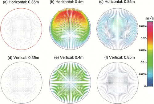
FIG. 8 Particle Trajectories for the “Case 2” simulations at furnace set-point temperature of 950°C for (a) horizontal tube (b) vertical tube.
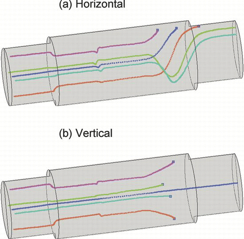
FIG. 9 Comparison of outlet size distribution for 90 nm particles at furnace set-point temperature of 950°C for “Case 2” simulations with horizontal and vertical tube configurations.
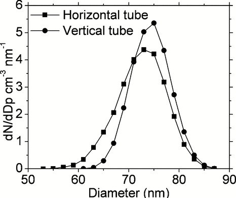
These results also suggest that TDMA measurements for soot oxidation would have well defined particle residence time profiles and sharply defined position of the peak diameter for vertical furnace configuration as opposed to horizontal furnace. The vertical furnace orientation would thus increase the measurement range to higher temperatures where the oxidation rate is faster.
5. DISCUSSION
Simulations suggest that assumptions made by CitationHiggins et al. (2002) neglecting effects of Brownian diffusion, thermophoresis and buoyancy induced recirculation flow within the reactor have lowest influence on shifting of the peak diameter of particles due to oxidation. Diffusion does not affect shape of the particle size distribution for given geometry, temperature and flow conditions, as most of the particles at the furnace outlet are greater than 10 nm diameter. However, thermophoresis is found to be the dominant mechanism affecting the shape of outlet particle size distribution within the furnace of interest.
Flow and temperature boundary conditions are found to be important variables affecting derivation of soot oxidation parameters. Better temperature measurements with higher resolution defining the radial and axial wall and gas temperatures are necessary. As shown in this work, uncertainties in temperature measurements could lead to a factor of 2 uncertainty in fitted kinetic parameter A nm when E a was fixed. Secondary flow and recirculation effects due to temperature induced buoyancy effects may be significant for laminar flow tube reactors in horizontal configuration. In this work, it is shown that buoyancy is less important as compared to inertia for the given geometry and flow conditions. However, radial flow and recirculation patterns are observed at entrance and exit of the heated zone of the furnace when gas temperature changes sharply. Smaller radial velocity patterns are also observed inside the heated zone of the furnace as furnace temperature profile changes in the axial direction. Secondary flow is found to be lower for the vertical furnace orientation as compared to the horizontal orientation. Also no significant influence of flow direction in the vertical furnace is found on predicted particle size distributions at the outlet. Secondary flow does not affect position of the peak particle diameter as observed from particle size distributions for horizontal vs. vertical tube orientations. However sharper well defined peak particle diameter is observed for the vertical orientation. Decrease in the peak particle diameter thus serves as a reliable indicator in deriving kinetic soot oxidation parameters in the laminar flow reactor.
This work could not explain the increasing broadening of particle size distributions towards smaller particle sizes at higher temperatures as compared to simulations. In addition, measurements for the particles of initial nominal size 40 nm show an additional “unexplained tail” towards larger particle sizes, which is not predicted by CFD simulations. Turning off thermophoresis in the model shows visually better agreement with measurements, however, the “no thermophoresis” simulations result in longer tail of particle size distribution towards smaller particles as compared to measurements. Also neglecting thermophoretic effects is not physically realistic, as thermophoretic effects are always present in high temperature soot oxidation studies. This unexplained distribution in particle size distribution curve implies that a distribution of temperature size-dependent particle reactivities may be present in the reactor. In theory, a distribution of oxidation rates could be fitted to measured particle size distributions with proper assumptions on deactivation, enhancement and reactivity distributions similar to CBK model (CitationHurt et al. 1998). Future work involving extensive experimental and theoretical investigations is needed to understand the distribution in oxidation rates for particles.
Acknowledgments
H.S.J. and M.S. thank Kelly Higgins for experimental data. The authors also gratefully acknowledge the suggestions from the anonymous reviewer regarding distribution of oxidation rates which helped improve the discussions in this manuscript significantly.
REFERENCES
- Bilde , M. and Pandis , S. N. 2001 . Evaporation Rates and Vapor Pressures of Individual Aerosol Species Formed in the Atmospheric Oxidation of Alpha- and Beta-Pinene . Environ. Sci. Technol. , 35 ( 16 ) : 3344 – 3349 .
- Chang , Y. C. , Ranade , M. B. and Gentry , J. W. 1990 . Thermophoretic Deposition of Aerosol Particles on Transport Tubes . J. Aerosol Sci , 21 ( Supplement 1 ) : S81 – S84 .
- Franz , B. , Eckhardt , T. , Kauffeldt , T. and Roth , P. 2000 . H2O2 Addition to Diesel Exhaust Gas and Its Effect on Particles . J. Aerosol Sci. , 31 ( 4 ) : 415 – 426 .
- Fuss , S. P. and Hamins , A. 2002 . Determination of Planck Mean Absorption Coefficients for HBr, HCl, and HF . J. Heat Transfer–Transactions of the Asme , 124 ( 1 ) : 26 – 29 .
- Gomes , M. S. P. , Pui , D. Y. H. , Vincent , J. H. and Liu , B. Y. H. 1993 . Convective and Diffusive Dispersion of Particles in Laminar Tube Flow – Effects on Time Dependent Concentration Measurements . J. Aerosol Sci. , 24 ( 5 ) : 643 – 654 .
- Gormley , P. G. and Kennedy , M. 1949 . Diffusion from a Stream Flowing through a Cylindrical Tube . Proceedings of Royal Irish Academy , 52A : 163 – 169 .
- Gupta , D. 1986 . Brownian Dynamics Simulation of Aerosol Coagulation: Effects of Shear Flow of Fluid, Brownian Motion and van der Waals Interaction , Ph.D. Thesis Rensselaer Polytechnic Institute .
- Higgins , K. J. , Jung , H. , Kittelson , D. B. , Roberts , J. T. and Zachariah , M. R. 2002 . Size–Selected Nanoparticle Chemistry: Kinetics of Soot Oxidation . J. Physical Chemistry A , 106 : 96 – 103 .
- Higgins , K. J. , Jung , H. J. , Kittleson , D. B. , Roberts , J. T. and Zachariah , M. R. 2003 . Kinetics of Diesel Nanoparticle Oxidation . Environ. Sci. Technol , 37 ( 9 ) : 1949 – 1954 .
- Holm , J. and Roberts , J. T. 2007 . Thermal Oxidation of 6 nm Aerosolized Silicon Nanoparticles: Size and Surface Chemistry Changes . Langmuir , 23 ( 22 ) : 11217 – 11224 .
- Hurt , R. , Sun , J. K. and Lunden , M. 1998 . A Kinetic Model of Carbon Burnout in Pulverized Coal Combustion . Combustion and Flame , 113 ( 1–2 ) : 181 – 197 .
- Jung , H. 2003 . Size-Selected Nanoparticle Chemistry: Kinetics of Soot Oxidation , Ph.D. Thesis University of Minnesota .
- Khalizov , A. F. , Earle , M. E. , Johnson , W. J. W. , Stubley , J. D. and Sloan , J. J. 2006 . Modeling of Flow Dynamics in Laminar Aerosol Flow Tubes . J. Aerosol Sci. , 37 ( 10 ) : 1174 – 1187 .
- Kim , S. H. , Fletcher , R. A. and Zachariah , M. R. 2005 . Understanding the Difference in Oxidative Properties between Flame and Diesel Soot Nanoparticles: The Role of Metals . Environ. Sci. Technol. , 39 ( 11 ) : 4021 – 4026 .
- Lin , J. S. and Tsai , C. J. 2003 . Thermophoretic Deposition Efficiency in a Cylindrical Tube Taking into Account Developing Flow at the Entrance Region . J. Aerosol Sci , 34 ( 5 ) : 569 – 583 .
- McMurry , P. H. , Takano , H. and Anderson , G. R. 1983 . Study of the Ammonia (Gas) Sulfuric–Acid (Aerosol) Reaction–Rate . Environ. Sci. Technol , 17 ( 6 ) : 347 – 352 .
- Nienow , A. M. , Roberts , J. T. and Zachariah , M. R. 2005 . Surface Chemistry of Nanometer–Sized Aerosol Particles: Reactions of Molecular Oxygen with 30 nm Soot Particles as a Function of Oxygen Partial Pressure . J. Phys. Chem , B 109 ( 12 ) : 5561 – 5568 .
- Qiang Wei , K. D. B. and Watts , W. F. 2001 . Single Stage Dilution Tunnel Performance SAE Technical Paper Nos. 2001–01–0201
- Sakurai , H. , Tobias , H. J. , Park , K. , Zarling , D. , Docherty , K. S. , Kittelson , D. B. , McMcMurry , P. H. and Ziemann , P. J. 2003 . On–Line Measurements of Diesel Nanoparticle Composition and Volatility . Atmos. Environ , 37 ( 9–10 ) : 1199 – 1210 .
- Song , D. K. and Dhaniyala , S. Evaluation of Brownian Motion Calculation using Discrete Phase Model of FLUENT . European Aerosol Conference . 2007 , Salzburg. Abstract T12A032
- Talbot , L. , Cheng , R. K. , Schafer , R. W. and Willis , D. R. 1980 . Thermophoresis of Particles in Heated Boundary–Layer . J. Fluid Mechanics , 101 ( DEC ) : 737 – 758 .
- Tsai , C. J. , Lin , J. S. , Aggarwal , S. G. and Chen , D. R. 2004 . Thermophoretic Deposition of Particles in Laminar and Turbulent Tube Flows . Aerosol Sci. Technol. , 38 ( 2 ) : 131 – 139 .
- Viskanta , R. and Menguc , M. P. 1987 . Radiation Heat–Transfer in Combustion Systems . Progr. in Ener. Combust. Sci. , 13 ( 2 ) : 97 – 160 .
- Zhou , L. , Rai , A. , Piekiel , N. , Ma , X. F. and Zachariah , M. R. 2008 . Ion–Mobility Spectrometry of Nickel Nanoparticle Oxidation Kinetics: Application to Energetic Materials . J. Phys. Chem , C 112 ( 42 ) : 16209 – 16218 .