Abstract
This article reports the results of an optimization procedure for a semivolatile aerosol dichotomous sampler (SADS) and experimental confirmation of the instrument's performance with an optimized sampler. Using numerical model results, the relationships between four major design and operating parameters significantly affecting the performance of the SADS and four performance parameters were expressed in log polynomial equations. Utilizing an optimization procedure, values for the major parameters giving the best performance were determined and used as the base model for optimizing minor parameters. Five minor parameters were then investigated for their possible contribution to better performance of the SADS. The optimal dimensions found were as follows: the diameter ratio between the nozzle and the collection probe was 1.30 and the length ratio of the distance between the nozzle and the collection probe divided by the nozzle diameter was 0.6. Among the minor parameters, only the entrance angle of the nozzle made noticeable improvement at 45°. Experimental tests confirmed that the performance of the new sampler was improved although not as much as expected from the numerical simulation.
INTRODUCTION
Sampling semivolatile aerosols for exposure assessment poses several challenges. Semivolatile aerosols are generated from semivolatile organic compounds (SVOCs), which have low vapor pressure between 10−4–10−11 atm (CitationBidleman 1988). In workplace environments, well known semivolatile aerosols that are associated with adverse health effects include metal removal fluid (MRF) mists, pesticides, asphalt fumes, and environmental tobacco smoke (CitationGuidotti et al. 1994; CitationWoskie et al. 1994; CitationBergman et al. 1996; CitationKriech et al. 2002). The compounds in semivolatile aerosols exist in both vapor and particulate form simultaneously at room temperature due to their low volatility (CitationBidleman 1988). Sampling only one phase will underestimate the potential exposure to SVOC aerosols. In particular, sampling only the particle phase using filtration can significantly bias the exposure due to evaporative loss during sampling (CitationRaynor and Leith 1999; CitationVolckens et al. 1999; CitationPark et al. 2003). Furthermore, evaluating the vapor and particle phases separately is important because each phase is absorbed into the human body by a different mechanism (CitationVolckens and Leith 2003).
Another situation in which separation of two phases is important is during sampling of volatile organic compounds (VOCs) coexisting with particles of another substance. Airborne particles may adsorb or solubilize the VOCs and bias exposure assessment for the VOCs (CitationCohen et al. 1992). Cohen et al. found that xylene concentrations measured using sorbent tubes connected behind glass fiber filters were statistically higher than those measured using only sorbent tubes in paint spray booths.
Conventional methods for sampling SVOCs and particles containing VOCs use various filter media or prefiltered sorbent tubes. Substantial evaporative loss has been reported for sampling methods using filter media (CitationRaynor and Leith 1999; CitationPark et al. 2003).
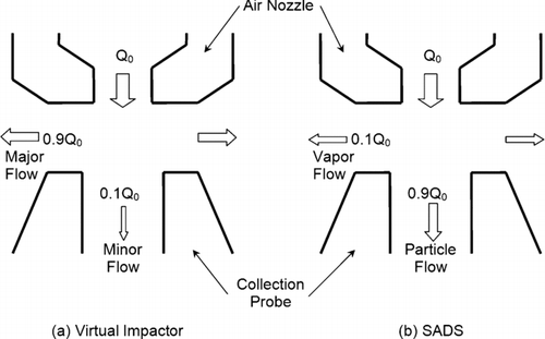
CitationKim and Raynor (2009) proposed and tested a semivolatile aerosol dichotomous sampler (SADS) to simultaneously measure particle and vapor concentrations more effectively than conventional methods can. SADS is a round nozzle virtual impactor for personal sampling. A virtual impactor is a modification to a conventional impactor in which the impaction plate is replaced with a collection probe drawing a fraction of the incoming air (CitationHounam and Sherwood 1965; CitationConner 1966). In conventional virtual impactors, typically about 90% of the air moves toward the major flow direction while the remaining 10% of air goes toward the minor flow direction (). In the SADS, the flow ratio between the major flow and the minor flow is inverted (). Because of the inverted flow ratio, the major and minor flows were redesignated in this article as “vapor flow” and “particle flow,” respectively, in the SADS. Using numerical modeling and experiments, CitationKim and Raynor (2009) demonstrated that the inverted flow ratio in the SADS allows separation of substantially smaller particles from the vapor flow than is possible if the same device is operated with flow ratios used typically for a virtual impactor.
FIG. 1 Diagram illustrating the differences in the SADS settings as compared to the virtual impactor settings.
Particles and vapor molecules separated by the SADS can be sampled by attaching various combinations of filter media and sorbent tubes to the outlets of each flow, providing independence from sampling media so that the SADS can be used in many different situations. On the other hand, the sampling media create additional back pressures to the sampling pumps on top of the back pressure from the SADS itself. Because SADS was designed to be used for personal sampling, the back pressure from different sources needs to be carefully considered when a sampling strategy is established.
Because particle separation in the SADS still uses the principle of inertial impaction as in virtual impactors, the parameters affecting the performance of virtual impactors may be important in the SADS settings. CitationMarple and Chien (1980) studied the effect of the air nozzle Reynolds number and the ratios between physical dimensions of virtual impactors on the particle collection efficiency by the numerical solution of the Navier-Stokes equations and of the equations of motion of the particles. CitationLoo and Cork (1988) studied these same factors experimentally. In both studies, the nozzle Reynolds number, the flow split ratio, the ratio between the nozzle diameter and the collection probe diameter, and the polished radius on the inner lip of the collection probe were identified as the most important parameters. CitationLoo and Cork (1988) also reported that the following parameters have a degree of importance: the entrance angle of the air nozzle, the length of the air nozzle throat, the thickness of the rim of the air nozzle, the thickness of the rim of the collection probe, and the nozzle-to-collection probe distance.
The importance of parameters may be different with SADS settings than with virtual impactor settings, since the design goals are different. Characterizing the effects of the parameters and finding the optimal settings for combinations of parameters are important in developing the best new sampler possible. Numerical modeling can be an efficient way of finding optimal conditions because of its flexibility and cost-effectiveness. CitationKim and Raynor (2009) built a 2-D axisymmetric numerical model using Fluent 6.2.14, a commercial computational fluid dynamics (CFD) code and validated the model experimentally.
Dimensional analysis is a conceptual method to investigate the relationships among different parameters and is used widely in scientific studies. In numerical modeling, this method allows us to simplify equations by reducing the number of variables and to approach situations systemically (CitationMunson et al. 2002). If an equation has k variables and r reference dimensions, it can usually be expressed with k−r dimensionless products.
In designing particle samplers that depend on inertial forces to collect particles such as cyclones, impactors, and virtual impactors, the dimensions of the devices and operating conditions determine their performance. When either experimental data or numerical models exist, it is possible to put the relationships between independent variables and performance variables into one or more equations and find the most desirable values within constraints. CitationLoo and Cork (1988) optimized physical dimensions of a virtual impactor experimentally. CitationRamachandran et al. (1991) studied cyclone optimization based on an empirical model. CitationHari et al. (2006) used numerical models to optimize a slit virtual impactor.
The objective of this research was to optimize the physical dimensions and the operating conditions of the SADS to improve its design so that it can sample SVOCs more accurately.
MATERIALS AND METHODS
Twelve parameters related to the separation of vapor and particles in the SADS were identified. For dimensional analysis and computer simulation, all the parameters were converted into nine dimensionless parameters. Based on the dimensionless parameters, a simulation model was built using commercial CFD software. That model was validated by CitationKim and Raynor (2009) by comparing its output to two sets of experimental data. Using the model, a full matrix of four major dimensionless design and operating parameters each with three levels (total of 81 parameter combinations) was simulated and the output data from the modeling runs were collected. Regression curves were obtained for each of four performance parameters as a log polynomial function of the four major parameters, and the regression equations were used together to find the optimal settings for combinations of design and operating parameters that best meet our design criteria. The best design was the one that had the smallest cutsize, pressure drop, and wall loss, and the steepest slope for its efficiency curve. Each of the steps in this process will be described in more detail below.
Dimensionless Parameters
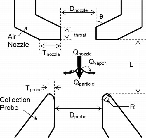
shows the nomenclature of the physical design parameters and the flow parameters which were used in this study. The diameter of air nozzle was 0.8 mm, the same as in the previous study (CitationKim and Raynor 2009). The following twelve variables are related to the separation of vapor and particles in the SADS: (1) the diameter of the air nozzle, Dnozzle, (2) the diameter of the collection probe, Dprobe, (3) the distance between the air nozzle and the collection probe, L, (4) the flow rate at the air nozzle, Qnozzle, (5) the vapor flow rate, Qvapor, (6) the particle density, ρ p , (7) the fluid density, ρ, (8) the fluid viscosity, μ, (9) the particle diameter, d p , (10) the vapor flow separation efficiency, ηvapor, (11) the pressure drop across the SADS, Δ P, and (12) the wall loss, WL. Here, ηvapor and WL were computed from:
Using the Buckingham pi theorem, the 12 variables were expressed in the form of nine dimensionless groups (CitationPerry 1973): (1) D probe/D nozzle, (2) L/D nozzle, (3) Stokes number (Stk), (4) ρp/ρ, (5) ηvapor, (6) Reynolds number (Re), (7) Q vapor/Q nozzle, (8) pressure coefficient (K), and (9) WL. Here, Stokes number, pressure coefficient, and Reynolds number are expressed as:
These functions were used in the CFD modeling and optimization procedures. ρp/ρ was not varied in this study because the aerodynamic diameter was used and incompressible fluid was assumed.
Based on the previous study (CitationKim and Raynor 2009) and the literature, we identified four major parameters that are the main factors that can affect the performance of the sampler significantly. Three levels of each major parameter were simulated as part of the full factorial design and were used subsequently for the optimization procedure. shows each parameter range compared with previous studies.
| • | D probe /D nozzle: This is the ratio between the nozzle diameter and the collection probe diameter. The designated values of this parameter were 1.6, 1.2, and 0.8, meaning Dprobe was 1.28, 0.96, or 0.64 mm for the standard Dnozzle of 0.8 mm. Particle losses near the cutoff size of a virtual impactor are strongly dependent on this parameter (CitationLoo and Cork 1988). These authors identified this parameter as one of the most critical for a virtual impactor, along with axial misalignment between the acceleration nozzle and collection probe and a polished radius on the inner lip of the collection probe. Because this is a conceptual numerical study, we assumed that there was no misalignment of axes. The polished radius was categorized as a minor parameter because it mainly affects the wall loss of particles, which was expected to be a small fraction in SADS settings from the previous study (CitationKim and Raynor 2009). | ||||
| • | L/D nozzle: This term stands for the ratio of the distance between the inlet nozzle and the collection probe to the nozzle diameter. In this study, the designated values of this parameter were 1.4, 1.0, and 0.6, meaning L was 1.12, 0.8, or 0.48 mm when Dnozzle was 0.8 mm. | ||||
| • | Re: The Reynolds number for the fluid inside a pipe is determined by Equation (Equation5). Because all values except Vnozzle are fixed, the Reynolds number depends on the total flow rate at the air nozzle. Values of 1000, 3000, and 5000 were modeled. At standard temperature and pressure, these values of Re were equivalent to values for Qnozzle of 0.57, 1.71, and 2.86 L/min for Dnozzle = 0.8 mm. These values spanned the expected transition from laminar flow to turbulent flow. In this range, the impaction efficiency curves for conventional impactors were found to be quite steep (CitationMarple and Liu 1975). If Re is too large, the pressure drop across the sampler will be excessive. If Re is too small within the air nozzle, then particles will not be accelerated enough to have the inertia necessary to be separated. Thus, finding an optimal point was especially important for this parameter. | ||||
| • | Q vapor /Q nozzle: Values of 0.025, 0.05, and 0.1 were modeled. For the values of Qnozzle noted previously, this led to a range of Qvapor from 0.014 to 0.29 L/min in dimensional terms. This flow ratio was the main difference from virtual impactors. Therefore, this was one of the most important parameters in the SADS. | ||||
TABLE 1 The ranges of simulation parameters and recommended values for the virtual impactors and the SADS
Numerical Simulations
The 2-dimensional (2-D) axisymmetric model used by CitationKim and Raynor (2009) was adopted to build the geometries for the CFD model. The computational domain was limited to the inside of the SADS. Sampler geometries and meshes and flow field solutions were achieved using GAMBIT 2.2.30. and FLUENT 6.1.16. (FLUENT Inc., Lebanon, NH), respectively. Dimensionless wall distance (y plus) for near-wall cells was kept less than 1. Uniform velocity was assumed at the inlet. The two outlets had outflow boundary conditions and their split ratio varied according to Qvapor/Qnozzle. The pressure at the inlet was assumed to be 1 atm. Turbulence in the computational domain was modeled using the standard k-ϵ model. No turbulent tracker was adopted. The initial turbulence kinetic energy (TKE) was set to zero because the initial velocity inside the calculation domain was set to zero. When the residual of mass flow rate reached less than 0.01% of the inlet mass flow rate, convergence was declared. The residual of mass flow rate is the summation of the absolute values of mass flow rate difference for each node between iterations. The calculation of trajectories of particles was accomplished using the same Lagrangian method as in the previous study (CitationKim and Raynor 2009).
Separation efficiency was also calculated in the same way as in the previous study (CitationKim and Raynor 2009). Two hundred spherical particles were imposed with equal inter-particle distance from the inlet wall to 0.05D nozzle away. The fate of the n-th particle away from the wall decided the fate of any particle entering in the circular area between the n−th and (n−1)-th particles. The flow rate was proportional to the size of the annular area between the n-th and (n−1)-th particles at the inlet, because uniform velocity was assumed at the inlet boundary. The diameters of imposed particles were between 0.1 and 1.0 μ m.
At first, all combinations of 2 geometrical parameters (Dprobe/Dnozzle and L/Dnozzle), for a total of 9 geometries, were built. Then, all combinations of 2 operational parameters (Qvapor/Qnozzle and Re), for a total of 9, were simulated on 9 geometries. A grand total of 81 simulations were performed.
Statistical Analysis and Optimization
In the optimization procedure, pressure drop was redefined as the average pressure drop at the particle flow outlet because additional pressure drop from the sampling media was expected to make the pressure drop at this outlet larger than at the vapor flow due to the relatively high flow rate in the particle flow. Vapor flow separation efficiency, ηvapor, was characterized by two different components, the Stokes number of 50% cutsize and the slope of the efficiency curve. The Stokes number of 50% cutsize, Stk50, was defined to be the corresponding Stokes number showing 50% separation efficiency. The slope of the efficiency curve was calculated by doubling the width between Stk75 and Stk50 on logarithmic scale. The maximum wall loss was selected from the relationship between wall loss and particle diameter for each simulation. These four dependent variables—Stk50, slope of the efficiency curve, maximum wall loss, and pressure coefficient—were calculated for each simulation.
Second order regression equations for the effect of the four major dimensionless design and operating parameters on each dimensionless performance parameter had the following form:
After calculating the log polynomial equations, the optimal conditions to best meet our design criteria were calculated using the solver function in Microsoft Excel (Microsoft, Redmond, WA). Using a Newton search method, the solver function found the minimum of a given function within constraints. The best design was the one that had the smallest Stk50, pressure coefficient, and wall loss, and the steepest slope. Because each performance parameter covered a different range of numbers, they were normalized to the averages of each parameter. Also, the importance of each performance parameter was considered. In this study, the 50% Stokes number was the most important parameter and the pressure coefficient acted as a constraint. Therefore, the 50% Stokes was weighted by a factor of 10 while other parameters were weighted by 1. In weighted optimization procedures, the weights describe which parameter is more or less important for the decision maker (CitationJahn and Krabs 1988). A value of 10 was chosen because, when three normalization methods were compared in preliminary evaluations, 10 was the smallest integer that made the procedures to find the smallest Stk50 in a single try. The entire optimization equation can be expressed as follows:
The SADS was designed to use for personal sampling. Therefore, the total back pressure, including that coming from sampling filters and sorbent tubes, should fall in the range which personal sampling pumps can handle for at least several hours. Most personal pumps can handle back pressures up to 7500 Pa (30 in. w.g.) at 2.0 lpm for 8 hours. Our measurements indicate that the back pressure from filter media was lower than 500 Pa (2 in. w.g.) and the back pressure from two activated carbon tubes (226-09, SKC Inc., Eighty Four, PA) connected in parallel was less than 3700 Pa (15 in. w.g.) at a combined flow of 2 lpm. These values would increase as chemicals are captured by the media during sampling. Therefore the maximum back pressure that can be allowed across the SADS itself is about 3300 Pa. Two levels of back pressure were modeled: 1490 Pa (6 in. w.g.) and 2490 Pa (10 in. w.g.), which correspond to approximately 50% and 75% of the maximum back pressure allowance, respectively.
Minor Parameters
The following 5 minor parameters were modeled individually using the optimal dimensions chosen from the optimization procedure. For each parameter, the value giving the minimum 50% cutsize was adopted. The other 3 performance parameters were not considered because their values were not changed substantially by changing the minor parameters.
| • | θ (The effects of the entrance angle): In their theoretical study, CitationMarple and Chien (1980) indicated fewer losses for 45° than for 30° entrance angles in virtual impactors. This was due to the particles being thrown closer to the center line for the large angle values, making the collection of particles in the probe slightly easier. CitationLoo and Cork (1988) recommended a range of 40° to 50° for virtual impactors. Entrance angles of 30°, 45°, and 60° were modeled. | ||||
| • | T throat /D nozzle (The length of the air nozzle throat): The effects of this parameter on the particle collection efficiency and the sampling loss in virtual impactors were reported as negligible in a theoretical study and an experimental study (Marple and Liu 1974; CitationMarple and Chien 1980). CitationLoo and Cork (1988) recommended a range of 0.8–1.2 for virtual impactors. Ratios of 0.0, 0.5, and 1.0 were evaluated. | ||||
| • | T nozzle /D nozzle (The thickness of the rim of the air nozzle): CitationLoo and Cork (1988) described this parameter as moderately influential and recommended values between 0.5 and 0.75 for virtual impactors. Thicknesses of 0.01, 0.5, and 1.0 were modeled. | ||||
| • | T probe /D nozzle (The thickness of the rim of the collection probe): CitationLoo and Cork (1988) used 0.36 for this parameter and described that this should be small enough to allow the dispersion of the radial air streams. On the other hand, a sharp rim can slightly increase the cutsize of a sampler. Thicknesses of 0.0, 0.5, and 1.0 were evaluated. | ||||
| • | R/T probe (The polished radius on the inner lip of the collection probe): CitationLoo and Cork (1988) used 0.82 for this parameter and described that this is essential in minimizing the loss peak near the cutsize. Radii of 0.0, 0.5 and 1.0 were modeled. | ||||
Experimental Comparison
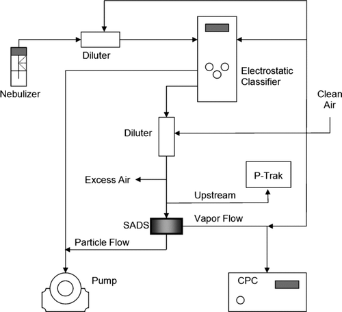
A new SADS was built based on the physical dimensions found from the optimization procedure and tested for its performance. The experimental method was similar to the one used by CitationKim and Raynor (2009). shows the experimental setup. Six different monodisperse particle suspensions having physical diameters ranging from 0.05 to 0.50 μ m were nebulized and classified using an Electrostatic Classifier (TSI Model 3071, Shoreview, MN). The counts of particles were measured upstream of the sampler and at the vapor flow using a P-Trak (TSI Model 8525, Shoreview, MN) and a Condensation Particle Counter (CPC) (TSI Model 3022, Shoreview, MN), respectively. At the start of each experiment, a P-Trak and a CPC were intercompared for upstream concentrations to verify that the counts were the same in each of these instruments. Separation efficiency (ηvapor) was calculated for flow ratio Qvapor/Qnozzle = 0.025 and 0.1. The combined flow rate was 2.0 lpm at which the corresponding Re was 3500, which was adjusted from that found to be optimal to allow for effective control of the flow. For each size of particle, experiments were repeated 3 times and averages and standard deviations were calculated.
To estimate the fraction of particles sampled from a particular size distribution through the vapor flow, the fractional mass sampled (FMS) was calculated using following equation:
RESULTS
From the results of the numerical simulations, four log polynomial equations were obtained using regression analysis as follows:
Using Equation (Equation13), the effects of Dprobe/Dnozzle and L/Dnozzle on Stk50 () and the effects of Qvapor/Qnozzle and Re on Stk50 () were estimated. The diameter ratio between the nozzle and the collection probe shows a second order relationship in so that local minima exist approximately at 1.15 for that parameter. However, this value was not chosen during the optimization procedure because at this ratio the pressure drop was always larger than the constraint set for that parameter. The optimal values for the four dependent variables were calculated from Equations (13)–(16) for two different pressure drops (). In both cases the optimal physical dimensions were identical.
FIG. 4 The effect of the physical parameters (Dprobe/Dnozzle and L/Dnozzle) on the cutsize of the SADS when Re = 3500 and Qvapor/Qnozzle = 0.1.
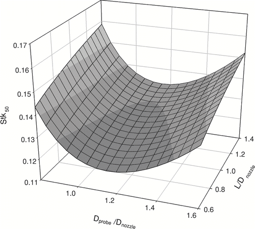
FIG. 5 The effect of the operational parameters (Qvapor/Qnozzle and Re) on the cutsize of the SADS when Dprobe/Dnozzle = 1.3 and L/Dnozzle = 0.6.
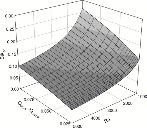
TABLE 2 Optimal values for independent parameters and corresponding dependent parameters from numerical modeling
With the optimal dimensions, FR = 0.1, and Re = 3500, the entrance angle was the only factor among the minor parameters found to have a noticeable effect on the performance parameters through the numerical model. Because an angle of 45° yielded the smallest Stk50, this angle was adopted for the optimal design. shows the final dimensions of the SADS and its expected performance parameters when flow rate at the inlet is 2.0 lpm (Re = 3500). Qvapor/Qnozzle = 0.1 was chosen rather than Qvapor/Qnozzle = 0.025 because the errors both from small particles entering the vapor flow and contributing to the vapor concentrations and from inaccurate vapor flow rates are magnified as FR decreases. The simulation results from the new CFD model built based on the optimization procedure showed good agreement with the expected values from the polynomial equations. Stk50, slope of the curve, wall loss, and pressure coefficient were 0.075 and 0.066, 0.34 and 0.33, 0.78% and 0.87%, 1.06 and 1.06, for the numerical model and the log polynomial equations, respectively.
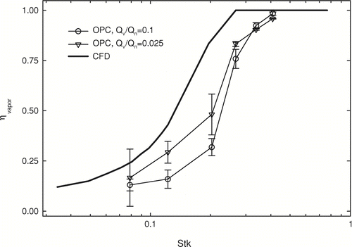
The SADS was built based on physical parameters determined in the numerical simulations and optimization procedure (). The Dnozzle was 0.8 mm and other dimensions were determined to be proportional to it accordingly. The separation efficiency of the SADS was tested and compared with that from the numerical simulation with the same settings (). The SADS was operated at 2.0 lpm. Stk50 at Qvapor/Qnozzle = 0.025 was smaller than that at Qvapor/Qnozzle = 0.1. However, the difference of Stk50 between two flow ratios was smaller than estimated from numerical simulations. The slope was sharper when Qvapor/Qnozzle was larger. At Qvapor/Qnozzle = 0.1, the Stk50 and the slope of the efficiency curve were 0.23 and 0.13, respectively. Stk50 was larger and the slope of the efficiency curve was sharper than expected from the modeling and optimization procedures.
FIG. 6 The SADS (lower left) built according to the optimization procedure has the outer shape of 37 mm cassette (lower right) and consists of two pieces, the air nozzle (upper left) and collection probe (upper right).
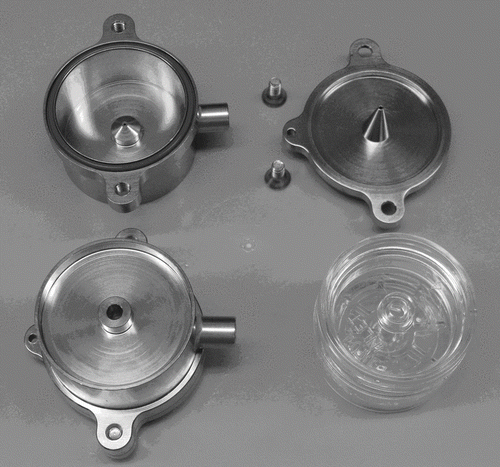
FIG. 7 Comparison of numerical results (CFD model) with experimental data when Re = 3500. In the CFD modeling, Qvapor/Qnozzle was 0.1 and in the experimental results, Qvapor/Qnozzle was 0.1 (○) and 0.025 (∇), respectively. Error bars represent one standard deviation at each size.
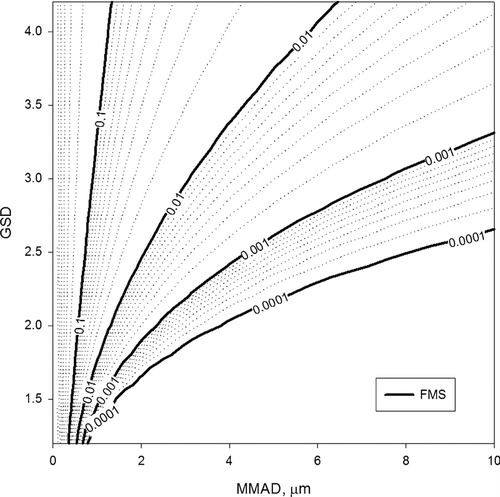
Estimated fractional mass sampled (FMS) was plotted as a function of MMAD and GSD in for Qvapor/Qnozzle = 0.1. When combinations of MMAD and GSD are to the right side of the FMS = 0.01 line in , less than 1% of particle mass can be expected in the vapor flow for the optimized SADS.
FIG. 8 Estimated fractional mass sampled (FMS) at the vapor flow according to Equation (Equation12) when Qvapor/Qnozzle = 0.1.
DISCUSSION
The diameter ratio Dprobe/Dnozzle of 1.30 for the optimized sampler was similar to that of virtual impactors studied by CitationMarple and Chien (1980) and CitationLoo and Cork (1988), 1.33 and 1.3–1.4, respectively. If there is no limitation on pressure drop, however, the optimal diameter ratio would become noticeably smaller than those of virtual impactors. The effect of diameter ratio on Stk50 was moderate over the simulation range as shown in . By adopting Dprobe/Dnozzl = 1.15, Stk50 can be reduced slightly while pressure drop will increase substantially. In general, if the ratio is too small, some fraction of the air flow from the nozzle will behave as in impactors so that some particles will deposit on the lip of the collection probe. If the ratio is too large, air flow from the nozzle will loosely split into two flows and less separation will occur because particles will have enough space to change their trajectories to follow the change of flow.
The optimal distances between the nozzle and the collection probe L/Dnozzle found in this study was 0.6, which was quite different from those reported by other studies on virtual impactors. CitationMarple and Chien (1980) and CitationLoo and Cork (1988) recommended 1.0, and 1.2–1.8 for this ratio, respectively. A likely reason for this difference is the smaller flow rate of the vapor flow in SADS settings compared to that of virtual impactors. The smaller the distance was, the smaller the cutsize was expected to be. This parameter was not decreased further than 0.6 because the wall loss was expected to increase and because the polynomial equations may not be trustworthy when extrapolated (CitationCochran and Cox 1992). From Equation (Equation15), the minimum wall loss was expected when the distance ratio was near 0.7.
Reynolds number based on the average throat velocity at the nozzle has been reported as a major parameter affecting the 50% cutsize of virtual impactors and a contributor to the sharper separation efficiency curve (CitationMarple and Chien 1980; CitationLoo and Cork 1988; CitationHari et al. 2006). Those facts were re-confirmed in this study. The effect of Re was larger when the flow split ratio Qvapor/Qnozzle was large (). The fact that decreasing Qvapor/Qnozzle decreases the 50% cutsize has been reported by several studies (CitationMarple and Chien 1980; CitationLoo and Cork 1988; CitationXiong et al. 1998; CitationHari et al. 2006). However, no existing study tested for Qvapor/Qnozzle < 0.5.
Among the 5 minor parameters, only the entrance angle at the nozzle showed a noticeable effect when it was altered. The optimal angle found was 45° and this result was similar to studies by CitationMarple and Chien (1980) and CitationLoo and Cork (1988), 45° and 40°–50°, respectively. The polished radius on the inner lip of the collection probe R/Tprobe was reported as a parameter significantly affecting the performance of virtual impactors (CitationLoo and Cork 1988). In this study, however, this parameter did not make a noticeable difference possibly because modeled wall loss is relatively small in SADS settings compared to virtual impactor settings. The fact that only a small fraction of air flows to the vapor flow direction in SADS settings may be another reason for the lack of importance for R/Tprobe because only a small space near the inner lip of the collection probe is required for particle separation.
The major design and operating parameters had 3 levels so that up to second order relationships have been observed as shown in Equations (13)–(16). Increasing the number of levels might increase confidence in the equations or reveal higher order relationships. However, that would require more computation time. Adding one more level to each major parameter would increase the computational time by more than a factor of 3. Four or five levels may be advisable when the ranges of factors are wide and the optimal point is poorly known in factorial experiments (CitationCochran and Cox 1992). In this study, the ratios between the minimum and the maximum of each range were no greater than 5.
A discrepancy between the CFD model results and experimental tests was found (), and the difference was larger than found in the previous study (CitationKim and Raynor 2009). In particular, the effect of flow ratio Qvapor/Qnozzle from the experiments was found to be smaller than expected from the CFD model. One reason for this discrepancy may be the non-axisymmetric structure of the real SADS. A 2-D axisymmetric model was adopted instead of a 3-D model because the 2-D model costs less computational time and less effort to build the mesh. Also, a more dense mesh could be added to the separation zone by choosing a 2-D model. Checking the results of 2-D using 3-D simulation might add insight to this difference in future work (CitationHu and McFarland 2008; CitationSeshadri et al. 2008). In addition, the outlet for the vapor flow had the shape of circumferential slit in the 2-D axisymmetric model. However, the built SADS had a tubing outlet in one direction (). This may have caused non-axisymmetric flow at the separation zone. In a preliminary study, fluorescent PSL particles were used to evaluate the separation efficiency of SADS. After sampling, we found particles deposited on the lip of the air nozzle in a non-axisymmetric pattern.
Another contributor to the discrepancy between the results of CFD modeling and experimental tests may be the turbulence model. For sub-micrometer particles in turbulent flow, in general, it is challenging to obtain accurate numerical predictions due to strong influence of the turbulent eddies on particles (CitationWang and Squires 1996). The standard k-ϵ model adopted in this study was one of the simplest turbulence models; it is a static model not including time dependence in the flow field equations. Therefore, this model could not encompass all the dynamics of turbulence that might happen in the calculation domain. In their visualization study, CitationHan and Moss (1997) showed that the flow inside the nozzle, inside the collection probe, and the space between them was laminar; whereas the vapor flow direction was turbulent when Re was between 2000 and 6000. Even considering that this could be changed as the flow split ratio was changed in SADS settings, the area where the flow split happens might still be turbulent. The particle separation zone which was expected to be the outer surface of the air column between the nozzle and the probe in SADS fell into the turbulent region (CitationHan and Moss 1997). Simplified initial and boundary conditions in the CFD model may be another reason for the discrepancy in . Initial and boundary conditions frequently affect results significantly in CFD modeling (CitationStern et al. 2001).
The SADS users need to know the size distribution of the aerosol they want to sample to understand the risk of misclassifying some of the particulate as vapor. When MMAD and GSD of aerosols are known, can be used to estimate sampling bias. For example, the MMADs and GSDs for oil mist were measured between 3.8–8.2 μ m and 2.2–3.7, respectively (CitationWoskie et al. 1994). In another study, the overall mean MMAD and GSD of oil mist was determined to be 4.9 μ m and 2.5, respectively (CitationPiacitelli et al. 2001). In these conditions, sampling using SADS will enable effective measurement of both phases with minimal bias.
Through the optimization procedure, a personal sampling device for semivolatile aerosols with a very low cutsize was produced. Stk50 decreased from 0.33 to 0.23. A low cutsize is important because it means that a superior separation of vapor from aerosols can be achieved. The slope of the efficiency curve became sharper with the optimization. Wall loss was expected to remain at a similar level to that of the previous version.
CONCLUSIONS
Dimensional analysis and numerical simulations revealed the relationships between design and operating parameters and performance parameters in the SADS. The diameter ratio between the air nozzle and the collection probe and the flow split ratio between vapor flow and particle flow had significant effects on all of the performance parameters of the SADS. Using equations defining these relationships, the optimization procedure improved the modeled performance of the SADS. Experiments on a SADS built according to the optimal design indicated that the built SADS had a lower cutpoint than previous versions, although not as low as the model had anticipated. Possible reasons for this less substantial improvement can be the non-axisymmetric geometry of the realized SADS after the optimization procedure and the fact that the starting point of the optimization procedure was already the optimized conditions of virtual impactors. The experiments indicate that the instrument will separate particles and vapor effectively for particles larger than 0.25 μ m in diameter.
Acknowledgments
This study was supported in part by a grant from the Pilot Project Research Training Program of the NIOSH-sponsored Midwest Center for Occupational Health and Safety at the University of Minnesota and in part by the University of Minnesota Supercomputing Institute.
Notes
a The entrance angle.
b The polished radius on the inner lip of the collection probe.
c not available.
a Dnozzle = 0.8 mm; Qnozzle = 2 L/min.
REFERENCES
- Aitken , R. J. , Baldwin , P. E. J. , Beaumont , G. C. , Kenny , L. C. and Maynard , A. D. 1999 . Aerosol Inhalability in Low Air Movement Environments . J. Aerosol Sci. , 30 ( 5 ) : 613 – 626 .
- Bidleman , T. E. 1988 . Atmospheric Processes—Wet and Dry Deposition of Organic Compounds are Controlled by Their Vapor-Particle Partitioning . Environ. Sci. Technol. , 22 : 361 – 367 .
- Bergman , T. A. , Johnson , D. L. , Boatright , D. T. , Smallwood , K. G. and Rando , R. J. 1996 . Occupational Exposure of Nonsmoking Nightclub Musicians to Environmental Tobacco Smoke . Am. Ind. Hyg. Assoc. J. , 57 : 746 – 752 .
- Cochran , W. G. and Cox , G. M. 1992 . Experimental Designs, , 2nd ed. , 356 – 357 . New York : John Wiley & Sons .
- Cohen , B. S. , Brosseau , L. M. , Fang , C. P. , Bower , A. and Snyhder , C. 1992 . Measurement of Air Concentrations of Volatile Aerosols in Paint Spray Applications . Appl. Occup. Environ. Hyg. , 7 : 514 – 521 .
- Conner , W. D. 1966 . An Inertial-Type Particle Separator for Collecting Large Samples . J. Air Pollut. Control Assoc. , 16 ( 1 ) : 35 – 38 .
- Fylstra , D. , Lason , L. , Watson , J. and Waren , A. 1998 . Design and Use of Microsoft Excel Solver . Interfaces , 28 : 29 – 55 .
- Guidotti , T. L. , Yoshida , K. and Clough , V. 1994 . Personal Exposure to Pesticide among Workers Engaged in Pesticide Container Recycling Operations . Am. Ind. Hyg. Assoc. J. , 55 : 1154 – 1163 .
- Hari , S. , Hassan , Y. A. and McFarland , A. R. 2006 . Optimization Studies on a Slit Virtual Impactor . Part. Sci. Technol. , 24 : 105 – 136 .
- Han , R. and Moss , O. R. 1997 . Flow Visualization Inside a Water Model Virtual Impactor . J. Aerosol Sci. , 28 : 1005 – 1014 .
- Hinds , W. C. 1999 . Aerosol Technology: Properties, Behavior, and Measurement of Airborne Particles, , 2nd ed , 49 New York : Wiley-Interscience Publication, John Wiley & Sons .
- Hounam , R. F. and Sherwood , R. J. 1965 . The Cascade Centripeter: A Device for Determining the Concentration and Size Distribution of Aerosols . Am. Ind. Hyg. Assoc. J. , 26 : 122 – 131 .
- Hu , S. and McFarland , A. 2008 . Circumferential-Slot Virtual Impactors with Stable Flow . Aerosol Sci. Technol. , 42 : 748 – 758 .
- Jahn , J. and Krabs , W. 1988 . “ Applications of Multicriteria Optimization in Approximation Theory ” . In Multicriteria Optimization in Engineering and in the Sciences , Edited by: Stadler , W. 64 New York : Springer .
- Kim , S. W. and Raynor , P. C. 2009 . A New Semivolatile Aerosol Dichotomous Sampler . Ann. Occup. Hyg. , 53 ( 3 ) : 239 – 248 .
- Kriech , A. J. , Kurek , J. T. , Wissel , H. L. , Osborn , L. V. and Blackburn , G. R. 2002 . Evaluation of Worker Exposure to Asphalt Paving Fumes Using Traditional and Nontraditional Techniques . Am. Ind. Hyg. Assoc. J. , 63 : 628 – 635 .
- Loo , B. W. and Cork , C. P. 1988 . Development of High Efficiency Virtual Impactors . Aerosol Sci. Technol. , 9 : 167 – 176 .
- Marple , V. A. and Chien , C. M. 1980 . Virtual Impactors: A Theoretical Study . Environ. Sci. Technol. , 14 : 976 – 984 .
- Marple , V. A. and Liu , B. Y. H. 1975 . On Fluid Flow and Aerosol Impaction in Inertial Impactors . J. Colloid Interface Sci. , 53 : 31 – 34 .
- Munson , B. R. , Young , D. F. and Okiishi , T. H. 2002 . Fundamentals of Fluid Mechanics. , 299 – 284 . New York : John Wiley & Sons .
- Nocedal , J. and Wright , S. J. 1999 . Numerical Optimization. , 19 – 27 . New York : Springer .
- Park , D. , Kim , S. and Yoon , C. 2003 . Loss of Straight Metalworking Fluid Samples from Evaporation During Sampling and Desiccation . Am. Ind. Hyg. Assoc. J. , 64 : 837 – 841 .
- Perry , R. H. 1973 . Chemical Engineer's Handbook, , 5th ed. , 2-81 – 83 . Columbus : McGraw-Hill Book Company .
- Piacitelli , G. M. , Sieber , W. K. , O'Brien , D. M. , Hughes , R. T. , Glaser , R. A. and Catalano , J. D. 2001 . Metalworking Fluid Exposure in Small Machine Shops: An Overview . Am. Ind. Hyg. Assoc. J. , 62 : 356 – 370 .
- Ramachandran , G. and Leith , D. 1991 . Cyclone Optimization Based on a New Empirical Model for Pressure Drop . Aerosol Sci. Technol. , 15 : 135 – 148 .
- Raynor , P. C. and Leith , D. 1999 . Evaporation of Accumulated Multicomponent Liquids from Fibrous Filters . Ann. Occup. Hyg. , 43 ( 3 ) : 181 – 192 .
- Seshadri , S. , Hari , S. , Hu , S. and McFarland , A. R. 2008 . A circumferential slot in-line virtual impactor . Aerosol Sci. Technol. , 42 : 40 – 49 .
- Stern , F. , Wilson , R. V. , Coleman , H. W. and Paterson , E. G. 2001 . Comprehensive Approach to Verification and Validation of CFD Simulations—Part 1: Methodology and Procedures . J. Fluids Engineering , 123 ( 4 ) : 793 – 802 .
- Volckens , J. , Boundy , M. , Leith , D. and Hands , D. 1999 . Oil Mist Concentration: A Comparison of Sampling Methods . Am. Ind. Hyg. Assoc. J. , 60 : 684 – 689 .
- Volckens , J. and Leith , D. 2003 . Partitioning Theory for Respiratory Deposition of Semivolatile Aerosols . Ann. Occup. Hyg. , 47 ( 2 ) : 157 – 164 .
- Wang , Q. and Squires , K. 1996 . Large Eddy Simulation of Particle-Laden Turbulent Channel Flow . Physics of Fluids , 8 ( 5 ) : 1207 – 1223 .
- Woskie , S. R. , Smith , T. J. , Hammond , S. K. and Hallock , M. H. 1994 . Factors Affecting Worker Exposures to Metal-Working Fluids during Automotive Component Manufacturing . Appl. Occup. Environ. Hyg. , 9 : 612 – 21 .
- Xiong , J. Q. , Fang , C. and Cohen , B. S. 1998 . A Portable Vapor/Particle Sampler . Am. Ind. Hyg. Assoc. J. , 58 : 614 – 621 .
