Abstract
The charging of micrometer-sized droplets in an electric field was examined experimentally using both direct and indirect droplet-charge measurements. Liquids with different dielectric constants (water, ethanol, and mineral oil) were studied. A specially designed low-noise charge detector was used directly to measure individual droplet charge. The total charge and droplet mean charge for an ensemble of droplets were obtained indirectly by current measurements. These were coupled with phase-Doppler anemometer droplet diameter, velocity, and flux measurements. Individual droplet charge also was determined indirectly via droplet trajectory analysis coupled with high-speed digital photography. All three methods were compared. In general, the droplet charge was found to depend on its position inside the charger, its dielectric constant, and the magnitude of the applied electric field.
1. INTRODUCTION
Charged aerosols are present in many aerosol applications, including xerography, electrospraying, and filtration. Charge can reduce or enhance the rate of particle coagulation or deposition on surfaces. An accurate determination of charge is essential, especially when optimizing devices, such as the size of an electrospray filtration system. This article presents a unique approach to individual real-time, precise droplet-charge measurement that was developed as a diagnostic for an in-flight electrospray system. Both direct and indirect measurements of the charge of droplets are considered, where the droplets are exposed to a negative-corona-discharge electric field in a needle-to-plate configuration.
Many charge-measurement methods have been developed. These can be classified as either direct or indirect. Direct methods involve having the droplet either physically contact the detector's surface or pass through the detector. Usually, both methods implicitly involve measuring the difference in potential (induced by the charged droplet) across a capacitor and then determining the charge from a calibration of potential difference versus charge. Indirect methods mainly include current measurements, trajectory deflection techniques, mass spectrometry, and Millikan-type experiments. While indirect methods are used frequently for many applications, a few studies involving direct methods, specifically used to characterize droplet behavior in corona chargers, have been made.
CitationHochrainer (1985) and CitationBrown (1997) have reviewed charge-measurement methods. The methods used by CitationHendricks and Yeung (1976), CitationKrupa and Jaworek (1989), CitationGreaves and Makin (1980), Donivan and Laukaitis (1981), and CitationAldred et al. (1983) have direct relevance to the present study. The most recent works have been presented by CitationMurtomaa et al. (2005), CitationGlover and Chan (2004), CitationMurtomaa (2003), CitationKulon and Balachandran (2001), and CitationMountain et al. (2001). compares the methods and charge ranges of these studies. For all studies cited, mean charge was reported.
TABLE 1 Some experimental charge-measurement methods
The present study and that of CitationHendricks and Yeung (1976) and of CitationKrupa and Jaworek (1989) involved direct-charge measurements. CitationHendricks and Yeung (1976) used a Faraday-cage technique to measure the charge on a single water droplet. Charge also was measured for an ensemble of droplets using a current technique. The reported charge ranged from 0.4 pC to 9 pC. CitationKrupa and Jaworek (1989) used a charge detector consisting of a wire with which charged droplets collided and transferred their charge. The wire was guarded by a concentric cylinder with two slots at its ends parallel to the droplet flow. Droplets, which were several hundreds microns in diameter, were charged using needle electrodes within an electric field. Individual droplet charge and accumulated charge were measured. The reported sensitivity of their system was 0.01 pC.
Some studies have measured accumulated charge or current using different methods and then indirectly determined the droplet or particle mean charge. These have used coarse conductive grids (CitationGreaves and Makin 1980; Donivan and Laukaitis 1981), a combination of conductive grids with a size-selective device (CitationAldred et al. 1983), an open-ended Faraday pail with a filter to collect samples (CitationMurtomaa et al. 2005), and a combination of an electrostatic precipitator and a Gerdien condenser (CitationKulon and Balachandran 2001). CitationGlover and Chan (2004) studied the charging of pharmaceutical aerosols in which the mean charges of 0.1 μ m to 10 μ m particles were measured in a low-pressure impactor. Mean charge, which was in the range from 10 pC to 300 pC, was obtained by integrating the current measured by an electrometer.
Other indirect methods, such as a deflection technique and a differential mobility analyzer can be used to determine the charge of an individual particle. However, certain assumptions, such as low Reynolds number, Re, and a small velocity relaxation time, need to be made. These methods were reported recently by CitationDalley J. et al. (2005), CitationFrank G. et al. (2004), and Lackowski M. et al. (2003) to characterize various chargers. Two types of charging techniques were used to impose the charge on aerosols: unipolar corona chargers and radioactive sources. While radioactive sources are utilized as an essential part for aerosol measurement and classification, corona chargers are popular for their use in electrostatic precipitators (ESPs). The efficiency of ESPs is related to the applied electric field. This has been known for a long time. However, few experiments have been performed to study how the charge of a liquid droplet can vary depending on the position inside the charger. Both CitationDalley et al. (2005) and Lackowski et al. (2003) used AC unipolar corona chargers to study the charging of particles from 3 μ m to 10 μ m with trajectory analysis. For characterization of a unipolar charger for liquid aerosols from 0.1 μ m to 20 μ m in diameter, α and β radioactive sources were used by CitationFrank et al. (2004). In their work, charge was measured with three different indirect methods involving mobility analysis. The first two methods were used to obtain the mean charge of droplets in the diameter ranges from 0.12 μ m to 0.61 μ m and from 4 μ m to 9 μ m. In the third method, the mean charge and the charge distribution function were obtained for 3 μ m to 17 μ m diameter droplets.
Each charge-measurement method has its limitations, which consequently limits the accuracy with which charge is measured. The most accurate indirect method is trajectory analysis. Although this method gives reasonable accurate results at low Re numbers, the effects associated with non-laminar flow around the droplet and non-spherical geometries can lead to additional uncertainty in the value of the charge. To minimize this, certain assumptions, such as empirical expressions for a drag force, are invoked. Among all approaches, direct methods are the most accurate. Thus, it is important to design the charge detector system which has a low noise level, high accuracy, and high sensitivity.
The goal of the present study was to develop a system that measures charges as small as from 0.1 fC to 1 fC under ambient conditions. In the present article, a new low-noise detector system for direct charge measurements is described. One direct and two indirect charge measurement methods and their application to study the in-flight charging of droplets of different liquids and various sizes in a corona field are considered. Emphasis is placed on the direct method, which measures individual droplet charge and provides the charge distribution of an ensemble of droplets. Unipolar chargers are used and operate in the field-charging regime under normal ambient conditions. The relation between the droplet charge and the applied electric field as well as measured ion currents are presented. The experimental results are compared with theoretical values. The limitations of each method are given.
2. EXPERIMENTAL
2.1. Apparatus and Technique
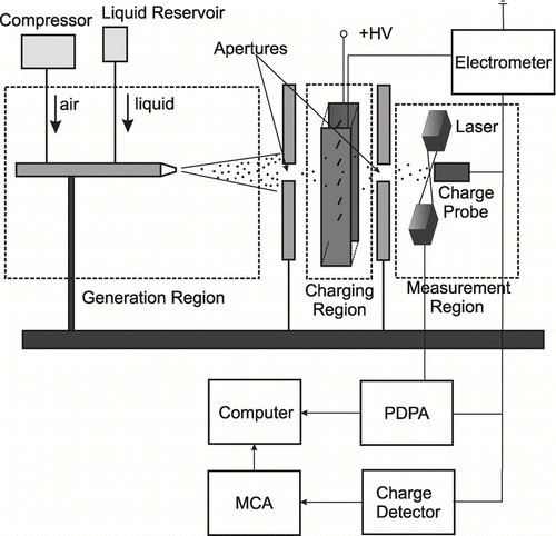
The experimental setup can be divided in three regions serving different purposes: generation, charging, and measurement. Droplets were produced in the generation region, charged in the charging region, and, finally, entered the measurement region where droplet data were taken.
Three different liquids (distilled water, ethanol, and mineral oil) were chosen to give a wide range of dielectric constants, which is a primary physical property affecting the magnitude of the droplet's saturation charge. The droplets were produced using two different configurations (I and II) that each gave a specific size range. The liquid properties, the droplet generation, and measurement techniques are summarized in .
TABLE 2 Liquid properties and their generation and measurement techniques
2.1.1. Configuration I
In configuration I, shown in , distilled water was dispersed using a Paasche air-brush under a static gauge pressure of 40 psi. This generated droplets with the diameter range from 1 μ m to 50 μ m. Dual apertures were used to eliminate large droplets and also to shield the detector from the electromagnetic noise generated by the corona discharge. These apertures also controlled the flow rate of the charged droplets and avoided water from accumulating on the surface of the charge probe. The jet of water droplets encountered the first aperture, passed through a corona discharge region, where they were charged. Then, the charged droplets passed through the second aperture and impacted the probe surface, thereby transferring their charge to the detector input. The experiment was conducted within the applied voltage range from 0 kV to 20 kV. At voltages greater than 20 kV, the droplets started to divert from their base-line paths (at zero applied voltage) and mostly missed the second aperture. This resulted in only large droplets reaching the detector, which in turn, altered the measured size-distribution function. Thus, in order to acquire measurements for the complete droplet-size range and to avoid any changes in the size distribution and the droplet flow rate, the applied voltage was limited to 20 kV.
2.1.2. Configuration II
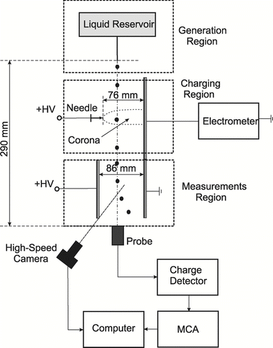
In configuration II, as shown in , mm-diameter ethanol and mineral oil droplets were generated through either a 27 gauge or a 24 gauge hypodermic needle that was attached to a liquid reservoir. Ethanol droplets with the mean radius of 1 mm and oil mineral droplets with the mean radius of 1.5 mm were formed as they emanated from the needle tip, which was placed at 29 cm from the charge detector probe. The droplet production rate in this case was approximately 0.5 droplets/s. Production of the same size droplets from different liquids was difficult to achieve. The liquids used had different densities, molecular viscosities and surface tensions, which resulted in different tension and gravitational forces. This, in turn, affected the size of the droplet, when it detached from the needle tip.
2.2. Charging Region
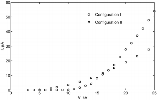
In configuration I, the corona discharge was created with 12 wire electrodes, each 0.34 mm in diameter and 1 cm in length. The distance between the tip of corona electrodes and the ground plate was 76 mm. In configuration II, the corona generator consisted of just one wire electrode and a grounded plate. One of the essential parameters that determines the droplet charging rate is the ion concentration, n i . The ion current, I, and the electric field, E, must be known to estimate the ion concentration in the charging region. The ion currents for both chargers were measured experimentally using the Keithley 6517A electrometer. The corresponding volt-ampere characteristics for each configuration are presented in , which shows a monotonic increase in current with increasing applied voltage.
A needle-to-plate electrostatic model was used to determine the electric field. In this model, the voltage is applied to a parabolic tip with a curvature radius, r w , located at some distance, L, from the ground plate perpendicular to it. The electric field generated in the space between electrodes as a function of the distance from the needle tip, x, can be expressed as (CitationFridman and Kennedy 2004)
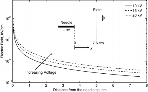
The electric field distributions for V = 10 kV, 15 kV, and 20 kV, when r w = 0.1 mm and L = 76 mm, are shown in . Here, it is assumed that the electric field generated by ions can be neglected, although in the very vicinity of the corona electrode (within approximately 1 cm), this assumption is not valid. To make allowance for the effects of the space charge electric field, more complicated models (see Benochi et al. 2006, for example) can be used. After determining I from experiments and E from Equation (Equation1), the ion concentration can be found.
FIG. 4 Electric field distribution for the needle-plate geometry as a function of the distance from the corona needle, as given by Equation (Equation1).
In the corona field, droplets are charged due to diffusion and field-charging processes. Diffusion charging depends on the thermal energy of ions. Field-charging is driven by the electric field. When the diameter of the droplets is larger than ∼ 1 μ m, diffusion charging can be neglected and the droplet charge is governed by Pauthenier's equation (CitationPauthenier and Moreau-Hanot 1932):
For the constant electric field, Equation (Equation2) can be integrated and the analytical solution for q(t) can be obtained as
In these expressions, q s is the saturation charge, ϵ0 is the vacuum permittivity, ϵ p is the dielectric constant of the droplet, e − is the elementary charge, μ is the ion mobility, r d is the radius of the droplet, t is the time and τ c is the charging time constant. The charging time constant depends on E and on the ion current density, J, as
Thus, by knowing n i or E and J, the charging time τ c can be found from Equation (Equation5). From the conservation of current, n i can be determined as n i = I/(e − μ ES eff ). Assuming that μ ∼ 10−4 m2/(V · s), E ∼ 105 V/m, as shown in , I ∼ 1 μ A to 10 μ A, as displayed in , and the effective area of the ground electrode, S eff ∼ 0.3 m2, the estimated ion density is n i ∼ 1013 m−3 to 1014 m−3. Accordingly, the charging time is τ c ∼ 1 ms to 10 ms. It is important to note here that this model is used for the purpose of estimating the charge and not to determining it precisely. For more detailed analysis, the dynamics of the falling drop must be considered.
2.3. Size and Charge Measurements
After passing through the charging region, the droplets entered the measurement region where their diameter and charge distribution were measured. The diameter distributions of the water droplets were measured with a Phase Doppler Particle Analyzer (PDPA) at 5 mm from the location of the surface of the charge detector probe. Ethanol and mineral oil droplet diameters were measured from images obtained using digital photography. For this purpose, a high-speed digital camera Fastcam Ultima APX with a MIKRO NIKKOR 105 mm optic lens were used.
One direct and two indirect charge-measurement techniques were employed: a charge detector (method I), current measurement (method II), and droplet trajectory (method III), respectively. The charge of water droplets (in configuration I) was measured using methods I and II. The charge of ethanol and mineral oil droplets (in configuration II) was measured using methods I and III. summarizes the methods and techniques that were used.
In method I, the charge was measured directly using a charge-detector system. This was comprised of a probe, a charge-detector circuit, and a multichannel analyzer that was interfaced to a personal computer. The charge probe consisted of a grounded cylindrical-shaped shield in which a small piece of 0.3 mm-diameter wire was mounted. The wire was connected to the input of the charge detector circuit using a shielded coaxial cable.
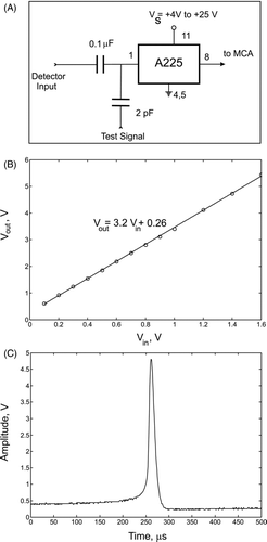
The heart of charge detector system was the A225 Amptek chip. This chip contained a charge-sensitive preamplifier developed especially for high-resolution systems in which the pulse height analysis is required. The system detects charges as small as ∼ 1 fC under ambient conditions, with 0.045 fC rms of noise. In the present study, the charge-measurement system was used to measure negative charges, although the system can be used for bipolar measurements with slight modification. It also can be used in atmospheric and vacuum environments. Its schematic is shown in the top plot (A) of . Before data collection, the detector was calibrated by injecting a test charge into its input. For this purpose, square-wave signals of a certain frequency and different amplitudes were generated to yield a range of output responses to different input charge levels. The detector was calibrated by measuring the amplitude of the input V in and of the output V out signals. The response characteristic of the chip was linear in the range from 0 V to 1.6 V, as shown in the middle plot (B) of , when no attenuation of the input signal was used. Beyond 1.6 V the chip became saturated. The minimum detectable charge was 1 fC and was determined by the level of the ambient electromagnetic noise. The maximum detectable charge was controlled by changing the sensitivity of the system using the RC circuit connected to A225 chip. In the present study, the maximum charge reached several hundred pC. The value of the test charge was calculated as q in = V in C in , where C in = 2 pF. The bottom plot (C) in displays an oscilloscope signal that was produced by a charged ethanol drop. By measuring the amplitude of the signal and using the calibration curve, the actual droplet charge was calculated. An Amptek multichannel analyzer, model MCA-8000, was used to perform the automatic peak detection of the signal and to collect the data in its 16384 active channels. The dynamic range from 0 V to 5 V was used for Configuration I, and from 0 V to 10 V for Configurations II and III. The analog-to-digital converter (A/D) digitized the pulse amplitude in less than 5 μ s. If a second pulse arrived while a pulse was being processed, it was held by the internal peak-hold detector. The second pulse was processed after the first pulse was digitized. Because of this two-stage storage method, the dead time following a single pulse could be as short as 2 μ s. The collected data then was sent to a personal computer using a RS-232 interface.
FIG. 5 (A) schematic of the A225 chip configuration, (B) A225 calibration curve, (C) example of an oscilloscope signal produced by a charged ethanol droplet.
In method II, the charge was determined using the current-measurement technique. This method used the Keithley 6517A electrometer connected to a probe, which consisted of a grounded cylindrical-shaped shield in which was mounted a small round plate of 5.1 mm radius that was connected to the central wire of the coaxial cable. When droplets impacted the probe surface, the discharge current through the electrometer was measured. The measurements of the droplet number concentration flux, F n d , which equals n d v d n , were taken simultaneously with the PDPA. Here, n d and v d n are the measured droplet concentration and the droplet velocity component normal to the surface of the probe. From this, the average charge was determined as
In method III, droplet trajectory analysis, also known as the deflection technique, was used. This is a simple yet effective method that involves measurements of the droplet deflection that results from the forces acting on the charged droplet in the applied electric field. The field was created with a high-voltage source connected to two parallel plates with 86 mm spacing. To determine the charge of the droplet, the x-momentum equation for aerosol motion was solved numerically. In the quiescent air and in the direction of the electric field lines, this equation can be written as
The trajectory analysis (method III) usually is limited to low-Re flows, small droplet relaxation times, and a spherical droplet geometry. In these cases, Equation (Equation7) is reduced to a steady-state equation with a Stokes force: q d E = 6π μ g r d v d x , where μ g is the gas (air) absolute viscosity. Although the deflection technique can be used for determining the individual droplet charge of both polarities, its use for large Re situations for ensembles of droplets can be rather laborious.
The direct-charge measurement method (I) presented here provides highly accurate measurements of individual droplets of both polarities regardless of droplet size and shape. It allows one to directly measure individual droplet charge as well as to analyze the charges of the multiple droplets. One of the limitations of this method is determined by a minimum peak time of A225 chip. After a droplet impacts the detector surface, it takes ∼ 2.5 μ s for the system to analyze the peak signal. If another collision occurs during this time interval, it will not be detected. Thus, the peak time gives limitation on the droplet collision frequency of ∼ 0.4 MHz.
A general uncertainty analysis was applied to find the combined uncertainty of each method u q . For the case of J measurands, the combined standard uncertainty is given by (CitationDunn 2010)
TABLE 3 Measured variables and their uncertainties
3. RESULTS
3.1. Configuration I
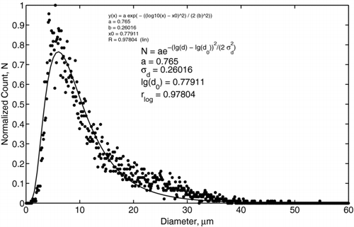
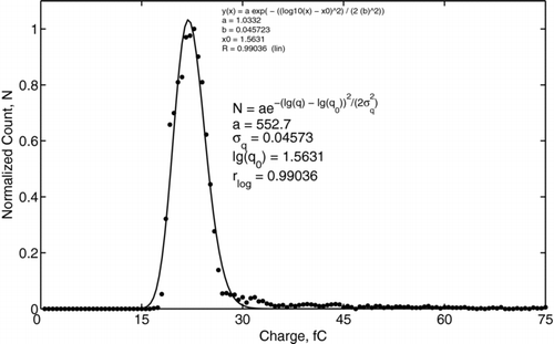
To ensure that there was no bias in the charge probe measurements, PDPA measurements were taken for both methods I and II at the location of the probes. These measurements revealed the same size distribution shown in . The measured size distribution of water droplets was found to be log-normal with the geometric mean diameter of 5.6 μ m, standard deviation of 3.3 μ m, and a diameter range from approximately 2 μ m to 40 μ m, as shown in . In contrast, the charge distribution did not exhibit such pronounced log-normal behavior. For example, the charge distribution for applied voltage of 20 kV is shown in , where the data is indicated by dots and the log-normal fitting is shown by a solid line. The fitting was based on a Nelder-Mead method (CitationNelder and Mead 1965), which performed an unconstrained nonlinear minimization of the sum of squared residuals with respect to the various parameters. The values of the correlation coefficients were 0.99036 for log-normal fitting and 0.99033 for normal fitting. Such a small difference makes it difficult to resolve the form of the charge distribution. This difference is a consequence of the narrowness of the charge distribution function and the fixed resolution of the MCA.
FIG. 7 An example of the charge distribution of water droplets obtained with Method I. The applied voltage is 20 kV. Dots depict the experimental data; the solid line indicates the log-normal fitting.
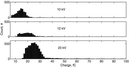
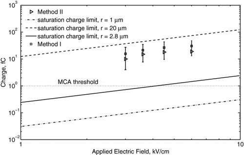
The measured charge distributions for water droplets are shown in for the applied voltages of 10 kV, 12 kV, and 20 kV. As the voltage and, accordingly, the electric field become higher, ions of higher kinetic energies are produced. Thus, droplets travelling through a corona region are charged to higher levels. This, consequently, affects the charge distribution, which is shifted along the abscissa toward higher values. The mean values and the standard deviation of the charge of water droplets measured with method I are presented in . For comparison, results given by method II as well as saturation charges given by Equation (Equation4) for the minimum (1 μ m), the maximum (20 μ m), and the mean (2.8 μ m) droplet radii also are shown. It is seen that method II gives the 20% lower mean charge values than those obtained with method I. This can be explained by the fact that the actual concentration of charged droplets was lower than the concentration measured by the PDPA system. This is because a fraction of the droplets were either uncharged or carried a charge lower than the minimum detectable level of 1 fC.
3.2. Configuration II
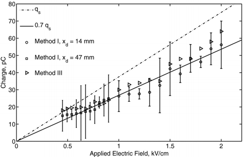
An example charge distribution obtained for 1 mm diameter ethanol droplets (Experiment II) is presented in for the applied voltages of 10 kV, 13 kV, 14 kV, and 20 kV. As the voltage increased, the distribution became broader because of the increased fluctuation of the corona discharge current. The resulting fluctuation of the body force caused different deflection of the droplet for the same applied electric field and different charge levels. The measured distribution function was log-normal, as shown in , which is in common with the measurements for monodisperse aerosols (CitationDalley et al. 2005). Using the model expressed by Equation (Equation1) for the distribution of an electric field, the acquired droplet charge as a function of the local electric field intensity was determined. The mean charges of ethanol and mineral oil droplets are presented in and , respectively. Here, different symbols represent the data measured at different locations from the needle tip with method I, and the error bars show ± the standard deviation of the charge distribution from the mean value. The distance between the needle tip and the center of the droplet was measured accurately using high-speed video camera to within ∼ 50 μ m. The data obtained with method III also are presented and agree with that of method I to within the experimental uncertainty. The linear best-fits, shown by solid lines, correspond to 80% of the saturation charge for ethanol droplets and to 70% of the saturation charge for mineral oil droplets. The fact that these values were lower than the saturation charge can be explained by the fact that the residence time of droplet in the corona region (∼ 1 ms) was of the same order or less than its charging time (τ c ∼ 1 ms to 10 ms), as given by Equation (Equation5). The measured charge of ethanol droplets varied in the range from 8 pC for the electric field of 0.4 kV/cm to 36 pC for the electric field of 1.3 kV/cm. The oil droplet charge varied in the range from 7 pC for the electric field of 0.4 kV/cm to 68 pC for the electric field of 2 kV/cm. The effect of dielectric constant becomes more evident when considering the surface charge density instead of the droplet charge. By taking into account that the mineral oil droplets are 1.5 times larger than the ethanol droplets, the surface charge density of the ethanol droplet is higher than that of the mineral oil droplet. Thus, ethanol can be considered a more favorable liquid for charging, which also is in agreement with the field-charging model.
FIG. 10 An example of the charge distribution measurements for ethanol droplets, obtained with Method I for different corona discharge voltages.
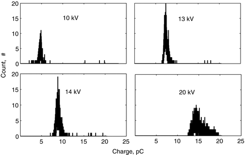
FIG. 11 An example of the charge distribution of ethanol droplets obtained with Method I. The applied voltage is 13 kV. The mean droplet radius is 1 mm. The dots depict the experimental data; the solid line is the log-normal fit.
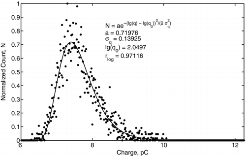
FIG. 12 Charge of ethanol droplets as a function of the applied electric field. Different symbols show the data at different x-locations from the needle tip. The dashed-dotted line represents the saturation charge, q s . The solid line represents 80% of a saturation charge value.
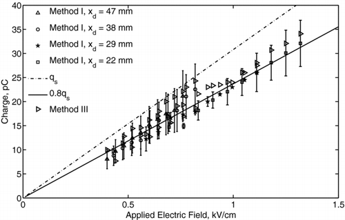
FIG. 13 Charge of mineral oil droplets as a function of the applied electric field. Different symbols show the data at different x-locations from the needle tip. The dashed-dotted line represents the saturation charge, q s . Solid line represents 70% of a saturation charge value.
Although the detector was used in an ambient environment, it can be used successfully under vacuum conditions, as was done with another charge-sensitive amplifier by CitationSrama and Auer (2008). The detector probe can be also modified to a ring configuration for non-intrusive measurements, the detailed review of which was recently published by CitationGajewski (2008).
4. SUMMARY AND CONCLUSIONS
A unique charge-measurement approach was presented, which has a better accuracy and dynamic range than other methods. Simultaneous charge and size measurements of polydisperse water droplets and of monodisperse ethanol or mineral oil droplets in the electric field of a corona charger under normal ambient conditions were performed using three different methods. These methods collectively use a PDPA system, a high-speed digital camera, and a specially designed charge detector system. The detector system measured charges as low as 1 fC in the present experiments. The system operated over a broad charge range and allowed data to be acquired in real-time when combined with multi-channel analysis. The detector system was tested using droplets charged in a corona field and its results were in agreement with the two other indirect methods. The evolution of the charge distribution as well as the mean charges were acquired as the applied electric field varied from 0.4 kV/cm to 2 kV/cm. The average droplet charge was determined to be lower than the saturation limit by approximately 20% for ethanol droplets and by approximately 30% for mineral oil droplets. It was also shown that droplets acquired different charge levels, depending on the distance from the corona electrode. This should be taken into account while assessing the efficiency of unipolar charger or designing an effective electrostatic-precipitation unit.
Partial stipend support of O.K. was provided through a research grant with The Procter and Gamble Company. We especially thank Dr. Vladimir Garstein and Dr. Alan Willey at P&G for their many technical interactions and support throughout this research.
REFERENCES
- Aldred , D. C. , Howe , A. F. and Wright , A. Size Selective Particle Charge measurement . Filtech Conf. pp. 342 – 346 .
- Benocci , R. , Urbano , M. and Mauri , L. 2006 . Study of a Positive Corona Discharge in Argon at Different Pressures . Eur. Phys. J. D. , 37 : 115 – 122 .
- Brown , R. C. 1997 . Tutorial Review: Simultaneous Measurement of Particle Size and Particle Charge . J. Aerosol Sci. , 28 : 1373 – 1391 .
- Clift , K. A. and Gauvin , W. H. 1970 . The Motion of Particles in Turbulent Gas Stream . Proc. Chem. E.C.A. , 1 : 14 – 24 .
- Dalley , J. E. J. , Greenway , R. S. , Ulanowski , Z. , Hesse , E. and Kaye , P. H. 2005 . Measurement of the Charge of Airborne 3–10 μ m Spherical Dielectric Particles Charged in an AC Unipolar Charger . J. Aerosol Sci. , 36 : 1194 – 1209 .
- Donivan , L. J. and Laukaitis , J. J. Device for Simultaneous Measurement of the Available Toner Concentration and Toner Charge of Dry Electrophotographic Developer . Proc. IEEE IAS . pp. 1094 – 1097 . IA–19, 6
- Dunn , P. F. 2010 . Measurement and Data Analysis for Engineering and Sciences , Taylor & Francis/CRC Press . ISBN: 9781439825686
- Frank , G. P. , Cederfelt , S. I. and Martisson , B. G. 2004 . Characterization of a Unipolar Charger for Droplet Aerosol of 0.1–20 μ m in Diameter . J. Aerosol Scie. , 35 : 117 – 134 .
- Fridman , A. A. and Kennedy , L. A. 2004 . Plasma Physics and Engineering , New York : Taylor & Francis .
- Greaves , J. R. and Makin , B. 1980 . Measurement of the Electric Charge From Aerosol Cans IAS Annual Meeting 28/9–31/10/80—Cincinnati 1075–1080
- Glover , W. and Chan , H. K. 2004 . Electrostatic Charge Characterization of Pharmaceutical Aerosols Using Electrical Low-Pressure Impaction (ELPI) . J. Aerosol Sci. , 35 : 755 – 764 .
- Gajewski , J. B. 2008 . Electrostatic Nonintrusive Method for Measuring the Electric Charge, Mass Flow Rate, and Velocity of Particulates in the Two-Phase Gas-Solid Pipe Flows—Its Only or as Many as 50 Years of Historical Evolution . IEEE Trans. Industry Applicat. , 44 ( 5 ) : 1418 – 1430 .
- Hendricks , C. D. and Yeung , K. F. 1976 . Technique of Single-Particle Charge Measurement . IEEE Trans. Industry Applicat. , IA-12 ( 1 ) : 56 – 63 .
- Hewitt , G. W. 1957 . The Charging of Small Particles for Electrostatic Precipitation . Trans. AIEE. , 76 : 300 – 306 .
- Hochrainer , D. 1985 . Measurement Methods for Electric Charge on Aerosols . Ann. Occup. Hyg. , 29 : 241 – 249 .
- Krupa , A. and Jaworek , A. 1989 . A Method for Aerosol Particle Charge Measurements . J. Electrostatics. , 23 : 289 – 292 .
- Kulon , J. and Balachandran , W. 2001 . The Measurement of Bipolar Charge on Aerosols . J. Electrostatics. , 51–52 : 552 – 557 .
- Mountain , J. R. , Mazumder , M. K. , Sims , R. A. , Wankum , D. L. , Chasser , T. and Pettit , P. H. 2001 . Triboelectric Charging of Polymer Powders in Fluidization and Transport Processes . Trans. AIEE. , 37 ( 3 ) : 778 – 784 .
- Murtomaa , M. , Strengell , S. , Laine , E. and Bailey , A. 2003 . Measurement of Electrostatic Charge of an Aerosol Using a Grid-Probe . J. Electrostat. , 58 : 197 – 207 .
- Murtomaa , M. , Pekkala , P. , Kalliohaka , T. and Paasi , J. 2005 . A Device for Aerosol Charge Measurement and Sampling . J. Electrostat. , 63 : 571 – 575 .
- Nelder , J. A. and Mead , R. 1965 . A Simplex Method for Function Minimization . Computer J. , 7 : 308 – 313 .
- Pauthenier , M. and Moreau-Hanot , M. 1932 . La Charge Des Particules Spheriques Dans Un Champ Ionise . Journal de Physique et la Radium. , 3 : 590 – 613 . (in French)
- Srama , R. and Auer , S. 2008 . Low-Charge Detector for the Monitoring of Hyper-Velocity Micron-Sized Dust Particles . Meas. Sci. Technol. , 19 : 1 – 8 .
