Abstract
The deposition of pure silica layers using the Outside Vapor Deposition method has been studied. The experimental study focuses on some fabrication parameters that have to be adjusted in order to work with a target temperature optimized for deposition of pure silica compatible with large volume deposition and post-treatments. It is experimentally shown that the optimized soot porous preforms are constituted by homogeneous silica spherical particles of 100 to 110 nm in diameter and have, in this case, densities approximately equal to 0.35 g.cm –3 .
1. INTRODUCTION
Several deposition methods have been proposed since the 1970s with the aim to fabricate high purity silica glass for the realization of optical fibers: the Vapor Axial Deposition process (VAD) (CitationIzawa 2000), the Modified Chemical Vapor Deposition (MCVD) (CitationNagel et al. 1982), the Plasma-activated Chemical Vapor Deposition (PCVD), and the Outside Vapor Deposition (OVD) (CitationBlankenship and Deneka 1982), which are respectively attributed to the NTT labs, the Bell labs, Philips GmbH and Corning Incorporated. Those precursory methods have then been improved and extended to various versions such as the Surface Plasma Chemical Deposition (SPCVD) (CitationPavy et al. 1986) and the Plasma Outside Vapor Deposition (POVD) methods (CitationVandewoestine and Morrow 1986).
The OVD method is considered nowadays as one of the most attractive and competitive processes for the industrial production of passive (Ge, P) and active (Er, Yb) optical fibers presenting high optical qualities meaning among other things low OH contaminations and low propagation losses (CitationNagel 1992; CitationSchultz 1980; CitationWang et al. 2008). This method is still the subject of many review papers (CitationBlankenship and Deneka 1982; CitationSchultz 1980; CitationWang et al. 2008) and of various detailed theoretical works (CitationFilippov 2003; CitationHong and Kang 1998; CitationKang and Greif 1993; CitationTandon et al. 2003; CitationTandon and Murtagh 2005; CitationTandon and Balakrishnan 2005; CitationWu and Greif 1996). However, it appears that only few experimental data have been reported in the literature (CitationCho et al. 1998; CitationGraham and Alam 1991) since the OVD process is subject to industrial and intellectual property rights. The report of a detailed experimental study on the fabrication of silica preforms using the OVD method is thus highly desirable in order to try to fill this lack in the literature.
2. GENERALITIES
2.1. The OVD Method
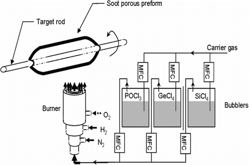
The silica preforms are fabricated using an OVD bench presented schematically in . The SiCl4 vapors are formed in bubblers maintained at controlled temperature close to the saturating vapor pressure of the halides. Using O2 as carrier gas, these vapors pass trough a heated line and are finally injected in the centre region of an annular H2/O2 burner. The temperature obtained from the reaction between H2 and O2 lead to the oxidation/hydrolysis of the SiCl4 vapors resulting in the formation of SiO2 particles as follows:
The formation of SiO2 particles is a quite complex process taking place in several steps. The precursors firstly react into the flame leading to the formation of individual glass molecules. Then, the molecules collide and agglomerate them forming silica glass particles. The particles are, after that, transported by the carrier gas flow and are submitted to the thermophoresis force that leads to their deposition on the target.
In a typical OVD apparatus, the target is rotating whereas the burner is translating along the length of the target. In our configuration, the burner was fixed and the target was rotating slowly and translating in the same time. In both configurations, successive layers of particles are, in this way, deposited on the target that forms a soot porous preform.
After the deposition, the soot porous preform is removed from the target and fed into a sintering system in order to be purified and vitrified (CitationSchultz 1980).
2.2. The Parameters of Fabrication
The parameters of fabrication can be classified into principally two main families: the mechanical and the chemical parameters. The mechanical parameters include roughly the translation/rotation target speed, the burner-to-target distance and the properties of the target. The chemical parameters correspond chiefly to the nature and the flows of the precursor, fuel, carrier and shield gas. Both of these two main families of parameters play a role on the soot porous preform properties and on the deposition efficiencies. Those parameters have been previously studied and some of their effects have been reported in the literature. Nevertheless the literature is scarce on the fabrication of fibers using the OVD method and only few data have been spread in the literature.
Mechanical parameters have been in this way reported. The target is said to be commonly an alumina rod with a diameter in the centimeter range (19.05 mm (CitationCho et al. 1998), 25.4 mm (CitationGraham and Alam 1991)). The translation and rotation speeds of the target are said to be mainly respectively around hundred millimeters per minute (5 to 20 cm.min–1 (CitationCho et al. 1998) and around ten rotations per minute (90 rpm (CitationCho et al. 1998), 45 rpm (CitationGraham and Alam 1991)). The number of passes depends on the size of the wanted soot preforms. Blankenship and Deneka's works (CitationBlankenship and Deneka 1982) were based on 1000 layers of deposition whereas Cho et al. studied the deposition of only few layers (6 passes) (CitationCho et al. 1998).
Indications on the nature of the gas as well on the gas flows have been moreover published. Cho et al. report the use of H2, O2, as fuel gas, N2 as shield gas and O2 as carrier gas with respectively the following flows 5.8 slm, 7.3 slm, 1 slm, and 0.3–0.7 slm (CitationCho et al. 1998). Graham and Alam report another set of gas flows using CH4 and O2 as fuel gas, O2 as carrier gas, without shield and with respectively the following gas flows 2.3 slm, 3.6 slm, 0.63 slm (CitationGraham and Alam 1991). The suitable set of gas flows is fixed by the characteristics of the burner which are seldom if ever reported in the literature and which are different for each investigator leading not possible any comparison (CitationGraham and Alam 1991).
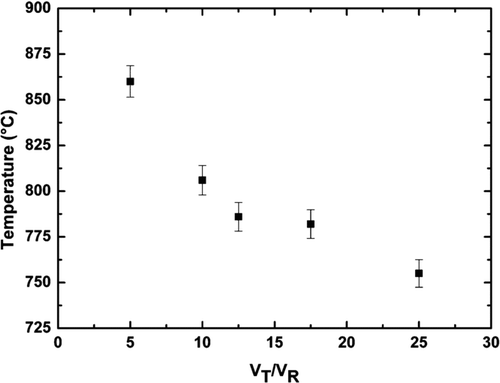
To easily adapt the parameters of fabrication whatever the burner used, we firstly studied the effect of the mechanical and chemical parameters on the deposition. It quickly appeared that all the parameters of fabrication such as the burner-to-target distance, the gas flows, the target translation/rotation speeds are tightly correlated and that they impact on the target temperature. To illustrate that effect, the influence of the rotation and translation target speeds on the target temperature has been plotted in .
For a given H2/O2 burner, it can be observed that the translation/rotation speed ratio impacts on the target temperature. As expected its value decreases with an increase of the translation/rotation speed ratio. In order to present experimental results useful whatever the burner used, we thus decided to present the temperature as a key parameter and to determine its optimal value to get homogenous silica preforms with high optical qualities.
3. RESULTS AND DISCUSSION
3.1. Fabrication Parameters
The soot porous preforms were fabricated keeping constant the SiCl4 (3 g.min–1) and carrier gas flows and the H2/O2 ratio (0.7). In this way, most of the parameters of fabrication were kept constant except H2 and O2 flows.
N2 was used as a shield gas separating the H2/O2 flame from the metallic halides and playing in this way two important roles: it firstly delays the oxidation/hydrolysis preventing the germination of SiO2 directly on the burner surface and, secondly, it helps to control the SiO2 particles trajectory from the burner output to the target.
The target was a cylindrical alumina rod maintained at fixed distance from the burner output. The deposition efficiency (η) and the soot preforms density (ρ) were calculated as follows:
The control of the target temperature was performed using a Raytek MP50 temperature scanner. In order to propose a comparative study, the temperature was recorded in the same conditions along the deposition whatever the silica soot preform. Hence, the depositions were performed on 10 cm length and the temperature measurements were realized at the same point on the first trip of each pass (forward and backward deposition).
All the results are summarized in . The relative uncertainty concerning the density (ρ) and the deposition efficiency (η) were experimentally estimated respectively equal to 5% and 10%.
TABLE 1 Parameters of deposition for a given configuration, tuning the O2/H2 gas flow
3.2. Properties of the Soot Porous Preforms
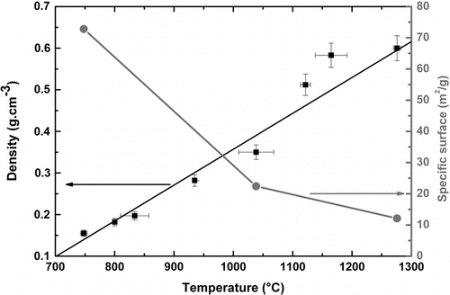
The influence of the target temperature on the densities of the soot porous preforms has been reported in . It is showed that from 750°C to 1300°C, the soot density increases linearly (ρ = 8.6 10–4.(T-700)) from 0.15 to 0.6 g.cm–3.
For target temperature lower than 750°C, no results have been reported since no deposition was observed in our configuration. The flame temperature is, using our set of gas parameters, not high enough to initiate the hydrolyzation/oxidation of the SiCl4 vapors. The flame was green on its whole length, which is interpreted as an incomplete reaction corresponding to the formation of intermediate chlorosiloxanes (CitationBinnewies and Jug 2000; CitationWu and Greif 1996).
For target temperatures included between 750°C and 900°C, the porous preforms present densities lower than 0.3 g.cm–3, which makes their handle difficult. Especially, it is tricky to remove properly the soot porous preform from the target. Inversely, during our investigations, the pure silica porous preforms deposited at 1400°C broke themselves during deposition due probably to their high density (> 0.7 g.cm–3) that creates thermomechanical constraints between the alumina target surface and the soot layers. These two observations suggest that the target temperature should be maintained between 900°C and 1400°C.
To go deeper in this analysis, the textural properties of three samples were determined using N2 adsorption-desorption measurements, and the specific surface area was deduced from the BET equation (CitationBrunauer et al. 1938). From 750°C to 1275°C, the specific surface area decreases from 73 to 12 m2.g–1 which confirms that the porosity of the samples decreases with an increase of the density. Moreover, the sorption analysis suggests that the porosity of the samples is in the scale of microporous size (CitationSing et al. 1985). It has to be mentioned that the surface areas and the porosity of the samples we report are in agreement with the values indicated by Schultz in 1980 (< 20 m2.g–1 for the surface area and approximately 0.3 μ m for the pore size).
3.3. Properties of the Silica Particles Forming the Soot Porous Perform
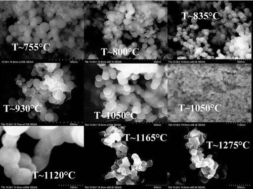
SEM pictures of the soot layers deposited at different target temperatures have been recorded (see ) and have been used to investigate the shape, size and size distribution of the particles constituting silica preforms.
For soot densities lower than 0.3 g.cm–3 (see , T < 900°C), the SEM analysis reveals that all the particles are spherical. Their diameter is in the 50–150 nm range without any dominant particle size. As can be observed on , an increase of the target temperature can be correlated to a homogenization of the distribution of the particle size. The particle size distribution has been adjusted using Gaussian function and we notice that increasing the target temperature the Full Width at Half Maximum (FWHM) for the Gaussian (w FWHM ) decreases from approximately (60+/–10) to (40+/–5) nm.
FIG. 5 Distribution of the silica particle size. The experimental data points extracted from have been adjusted using a Gaussian function.
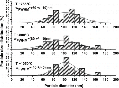
For a target temperature approximately equal to 1050°C (soot density close to 0.3 g.cm–3), the particles which constitute the soot porous preforms are spherical and homogeneous in size. Their diameter is mainly included between 100 to 110 nm ( and , T ∼ 1050°C). For densities higher than 0.5 g.cm–3, the particles start to sinter together (, T ∼ 1120°C). Increasing again the temperature, it appears that the particles that are deposited on the mandrel are no more spherical (, T ∼ 1165–1275°C). It can be assumed that working at higher temperature will emphasize this effect since the particles are no more homogeneously distributed. This effect could have a drastic impact on the optical properties since an efficient purification of these porous layers is complicated.
The SEM analysis leads to reduce the temperature interval previously estimated suitable for the realization of pure silica preforms. The optimal target temperature domain is indeed reduced to (1050 +/– 100)°C. The optimized soot porous preforms present densities of (0.35 +/– 0.02) g.cm–3 and they are mostly formed by spherical silica particles with a diameter mainly included between 100 to 110 nm. Our interpretation is in agreement with the literature results reporting that soot particle diameter is within the nanometer range (typically 10–100 nm for CitationSchultz (1980), approximately 100 nm for CitationBlankenship and Deneka (1982) and in the range of 150–500 nm for CitationGraham and Alam (1991)) and that the porous preforms density is about 15–25% of the bulk glass density (CitationBlankenship and Deneka 1982). It has to be mentioned that our study gives a strict and narrow range of suitable particle sizes and of appropriate soot porous preform densities.
3.4. Deposition Efficiency
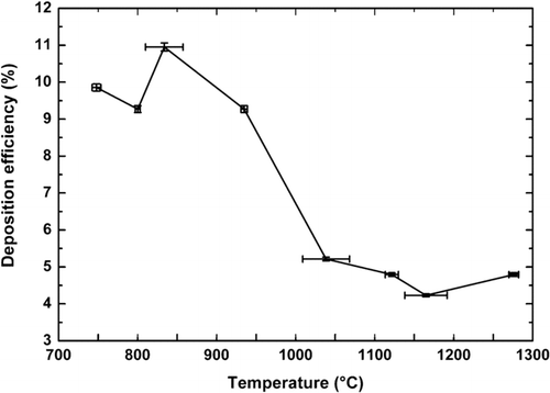
The above-chosen conditions of fabrication are nevertheless fixed to the detriment of the deposition efficiency (). As plotted on the , its value decreases from 10 to 5% when the target temperature increases from 700°C to 1300°C, leading to relatively low deposition efficiencies.
FIG. 6 Influence of the target temperature on the deposition efficiency (15 deposited layers for each sample).
The evolution of the deposition efficiency (η) is well established and it is expressed as follow (CitationHong and Kang 1998):
The temperature gradient corresponds to the partial derivatives of the temperature expressed above in the thermophoretic velocity equation. Its increase leads to an increase both of the velocity of the SiO2 particles and of the deposition efficiency (η) (CitationWu and Greif 1996).
As observed experimentally and as already mentioned the target temperature is a key parameter which is responsible for the soot properties and for the deposition efficiency.
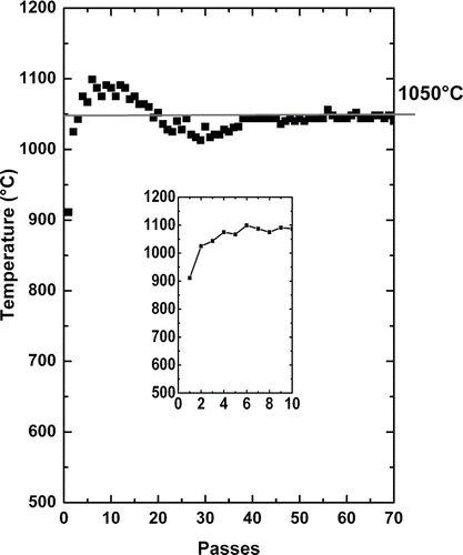
To fabricate homogeneous preforms, the challenge during the OVD process consists in controlling the target temperature value in order to avoid, along the process, any of its fluctuation which can occur because some fabrication parameters (target diameter) vary increasing the number of passes.
The typical evolution of the target temperature along the process is reported on the . In our configuration, during the first 10 passes, its value increases and is then controlled after 35 passes to be maintained at around 1050°C to get a porous preform presenting a density of about 0.35 g.cm–3.
For the first passes, the increase of the target temperature tends to decrease the deposition efficiency as described by CitationCho et al. (1998). In our case, increasing the number of passes, we observe that the deposition efficiency rises with the number of deposited layers. In this way we observe experimentally that for 10 passes of deposition, the deposition efficiency is about 5.2% and it increases up to 10% for 75 passes. The previous authors performed their study depositing only few layers (6 passes) which maybe didn't allow them to put this effect in evidence. The increase of the deposition efficiency as function of the number of passes (number of passes > 35) can be explained by the increase of the target diameter which favors the deposition efficiency since the target will totally cover the silica particle flow formed at the end of the burner.
Our deposition efficiency are nevertheless relatively low compared with the literature results since some authors relate deposition efficiencies going up to 100% (Bautista and Atkins 1991). Regarding the literature results it can be expected that our deposition efficiency could be enhanced during the realization of large volume preforms due to the increase of the number of deposited layers. Graham and Alam reported indeed that to increase the efficiency of deposition the ratio of the mandrel diameter to the jet exit diameter has to be 2.31 (CitationGraham and Alam 1991) whereas at the beginning of our deposition its value was about 1 meaning that the target diameter didn't fit to the flame size.
3.5. Optical Properties of the Silica Performs
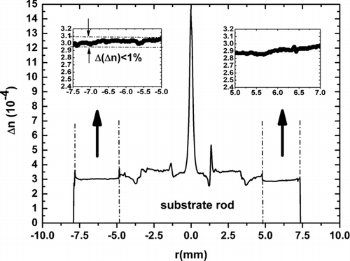
To study the optical properties of the preforms, soot porous preforms have been sintered at around 1500°C using appropriate gas allowing purifying the preforms and thus reducing the OH contaminations (CitationSchultz 1980). Depositions of 50 layers were carried out on a commercially available silica rod (Heraeus LWQ100) controlling the target temperature by tuning the O2 and H2 gas flows. The deposited sintered layers presented a thickness of 2.5 mm, meaning that each sintered layer measures around 50 μ m. The refractive index profile measured at 1.5 μ m using a P106 Photon Kinetics Preform Analyser, presents Δ n variations (Δ(Δ n)) lower than 1% ().
FIG. 8 Refractive index profile (Substrate rod corresponds to a commercial silica rod reference Heraeus LWQ100).
Fourier Transformed Infra-Red (FTIR) absorption has been recorded around 3675 cm–1, the wavenumber domain corresponding to the vibration energy of Si-OH groups. Applying the protocol described in CitationHumbach et al. (1996), it is then possible to estimate the hydroxyl concentration. Even if the sensitivity of our setup did not allow to precisely determining the OH concentration, it appears that, based on the known sensitivity of the apparatus, the OH contamination in the sintered preform was smaller than 500 ppb. Additional measurements are necessary to check that this value is in the range of those reported in the literature (< 50 ppb) (CitationBlankenship and Deneka 1982).
4. CONCLUSION
An experimental study of the fabrication of pure silica preforms has been performed using the Outside Vapor Deposition method. This study indicates that the target temperature acts as a key parameter playing a role on the deposition efficiency as well on the soot properties. The challenge to get preforms presenting high optical qualities consists in controlling the target temperature and avoiding any of its possible fluctuation along the process.
Working with target temperatures included between 750 and 900°C favors the deposition efficiency (10%) whereas the silica particles are not homogenously distributed. Inversely, working at high temperature (> 1150°C), disadvantages the deposition efficiency (∼ 5%) in addition to the fact that the SiO2 particles are no more spherical and start to sinter together. The target temperature is indeed a drastic parameter that has to be maintained at around 1050°C all along the process. In this configuration, the soot porous preforms present densities approximately equal to 0.35g.cm–3. The SiO2 particles are pretty well spherical with a controlled diameter of about (100 +/– 10) nm. The optical quality of the soot porous preforms is thus favored to the detriment of the deposition efficiency (5%).
This work was partly performed in the frame of the NextGenPCF research project, funded by the IST program of the European Commission's 6th Framework. This work was also supported by the Conseil Régional Nord Pas de Calais.
REFERENCES
- Bautista , J. R. and Atkins , R. M. 1991 . The Formation and Deposition of SiO2 Aerosols in Optical Fiber Manufacturing Torches . J. Aerosol Sci. , 22 ( 5 ) : 667 – 675 .
- Binnewies , M. and Jug , K. 2000 . The Formation of a Solid from the Reaction SiCl4(g) + O2(g) – > SiO2(s) + 2Cl2(g) . Eur. J. Inorg. Chem. , 2000 ( 6 ) : 1127 – 1138 .
- Blankenship , M. G. and Deneka , C. W. 1982 . The Outside Vapor Deposition Method of Fabricating Optical Waveguide Fibers . IEEE J. of Quantum Elec. , QE-18 ( 10 ) : 1418 – 1423 .
- Brunauer , S. , Emmett , P. H. and Teller , E. 1938 . Adsorption of Gases in Multimolecular Layers . J. Am. Chem. Soc. , 60 : 309 – 319 .
- Cho , J. , Kim , J. and Choi , M. 1998 . An Experimental Study of the Heat Transfer and Particle Deposition During the Outside Vapor Deposition Process . Int. J. Heat Mass transfer. , 41 ( 2 ) : 435 – 445 .
- Filippov , A. V. 2003 . Simultaneous Particle and Vapor Deposition in a Laminar Boundary Layer . J. Coll. and Int. Surf. , 257 : 2 – 12 .
- Graham , G. M. and Alam , M. K. 1991 . Experimental Study of the Outside Vapor Deposition Process . Aerosol Sci. Technol. , 15 : 69 – 79 .
- Hong , K. H. and Kang , S. H. 1998 . Three-Dimensional Analysis of Heat Transfer and Thermophoretic Particle Deposition in OVD Process . Int. J. Heat Mass Transfer. , 41 ( 10 ) : 1339 – 1346 .
- Humbach , O. , Fabian , H. , Grzesik , U. , Haken , U. and Heitmann , W. 1996 . Analysis of OH Absorption Bands in Synthetic Silica . J. Non-Cryst. Sol. , 203 : 19 – 26 .
- Izawa , T. 2000 . Early Days of VAD Process . IEEE J. on Sel. Top. In Quant. Elec. , 6 ( 6 ) : 1220 – 1227 .
- Kang , S. H. and Greif , R. 1993 . Thermophoretic Transport in the Outside Vapor Deposition . Int. J. Heat Mass Transfer. , 36 ( 4 ) : 1007 – 1018 .
- Nagel , S. R. , MacChesney , J. B. and Walker , K. L. 1982 . An Overview of the Modified Chemical Vapor Deposition (MCVD) Process and Performance . IEEE J. of Quant. Elec. , QE-18 ( 4 ) : 482 – 496 .
- Nagel , S. R. 1992 . R&D Directions for Optical Fiber . IEEE LTS , 3 ( 4 ) : 26 – 34 .
- Pavy , D. , Moisan , M. , Saada , S. , Chollet , P. , Leprince , P. and Marrec , J. . Fabrication of Optical Fiber Preforms by a New Surface Plasma CVD Process . Proceedings of the 12th European Conference on Optical Communication . Barcelona. pp. 19 – 22 .
- Schultz , P. C. 1980 . Fabrication of Optical Waveguides by the Outside Vapor Deposition Process . Proceedings of the IEEE , 68 ( 10 ) : 1187 – 1190 .
- Sing , K. S. W. , Everett , D. H. , Haul , R. A. W. , Moscou , L. , Pierotti , R. A. , Rouquerol , J. and Siemieniewska , T. 1985 . Reporting Physisorption Data for Gas/Solid Systems with Special Reference to the Determination of Surface Area and Porosity (Recommendations 1984) . Pure Appl. Chem. , 57 ( 4 ) : 603 – 619 .
- Tandon , P. , Terrell , J. P. , Fu , X. and Rovelstad , A. 2003 . Estimation of Particle Volume Fraction, Mass Fraction and Number Density in Thermophoretic Deposition Systems . Int. J. of Heat and Mass Trans. , 46 : 3201 – 3209 .
- Tandon , P. and Murtagh , M. 2005 . Particle-Vapor Interaction in Deposition Systems: Influence on Deposit Morphology . Chem. Eng. Science , 60 : 1685 – 1699 .
- Tandon , P. and Balakrishnan , J. 2005 . Predicting Heat and Mass Transfer to a Growing, Rotating Perform During Soot Deposition in the Outside Vapor Deposition Process . Chem. Eng. Science , 60 : 5118 – 5128 .
- Vandewoestine , R. V. and Morrow , A. J. 1986 . Developments in Optical Waveguide Fabrication by the Outside Vapor Deposition Process . J. Lightwave Techn. , LT-4 ( 8 ) : 1020 – 1025 .
- Wang , J. , Gray , S. , Walton , D. T. , Li , M.-J. , Chen , X. , Liu , A.-P. and Zenteno , L. A. 2008 . Advanced Vapor-Doping, All-Glass Double-Clad Fibers Proceedings of SPIE 6890:689006
- Wu , C. K. and Greif , R. 1996 . Thermophoretic Deposition Including an Application to the Outside Vapor Deposition Process . Int. J. Heat Mass Transfer. , 39 ( 7 ) : 1429 – 1438 .
