Abstract
Researchers at NIOSH are developing methods for characterizing ultrafine aerosols in workplaces. One method includes the detailed analysis of collected particles using electron microscopy (EM). In order to collect samples for EM at remote workplaces including mining and manufacturing facilities, researchers have developed a handheld electrostatic precipitator (ESP) particle sampler capable of collecting airborne particles including nanoscale materials, for subsequent EM analysis. The handheld ESP has been tested in the laboratory and is currently undergoing beta testing in the field. Gross collection efficiencies were measured with a CPC and net efficiencies by EM analysis of collected samples. Using laboratory-generated NaCl aerosols in the 30–400 nm size range at a flow rate of 55 cc/min and ESP operating voltages between 5.6–6.8 kV, both gross and net efficiencies were measured and showed a similar correlation with voltage, with maximum efficiency of approximately 86% at 6.4 kV. EM images from samples were also used to estimate particle size distributions of the original aerosols and the size-dependent deposition was evaluated for upstream versus downstream locations on the sample media. Results suggest that the number concentration and particle size distribution of sampled aerosols may potentially be estimated from a single ESP sample, but that the accuracy and repeatability of such quantification need to be investigated and refined. NIOSH is planning to license the ESP sampler for commercial manufacturing.
1. INTRODUCTION
The authors are conducting research on the characterization and mitigation of hazardous airborne pollutants in workplaces such as refineries, mills, and manufacturing facilities. In addition, with the advent of nanotechnologies, processes that produce nanoparticles or that have nanoscale waste materials are potentially exposing workers to a new generation of airborne hazards. Since nanomaterials have the potential for enhanced bioavailability and thus detrimental health effects (CitationOberdoerster 2001; CitationCardello et al. 2002; CitationIbald-Mulli et al. 2002; CitationKandlikar et al. 2007), the authors and others have begun to focus research on the characterization of nanoaerosols in workplace environments. Much of that work is focused on measuring the number, size, and available surface area of aerosols in the workplace (in addition to their mass concentration, which is more commonly measured). There is also a demonstrated need for more detailed morphology characterization of airborne particles (CitationOberdoerster et al. 2005; CitationBalbus et al. 2007) and our work therefore includes developing methods for detailed particle characterization by electron microscopy (EM).
A common approach for assessing workplace aerosols is to do a field survey of the entire workplace, using a variety of instruments to gather data (CitationMethner et al. 2007; CitationEvans et al. 2008). To this end, the authors are developing a portable system for evaluating airborne hazards in the workplace. The system entails making measurements using real-time direct reading instruments, along with the use of custom designed software for logging the data and generating 2-D tomographic maps of the information. Guided by the maps, spot samples are collected at key locations in the workplace for subsequent detailed characterization and speciation of the aerosol particles using techniques including transmission electron microscopy (TEM), scanning electron microscopy (SEM), and energy dispersive spectroscopy (EDS). To simplify such spot sampling under field conditions, the authors have developed a portable electrostatic precipitator (ESP) particle sampler. This article describes the design and evaluation of the handheld ESP.
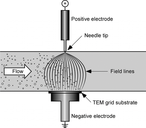
The basic operation of an ESP particle sampler entails the routing of the subject aerosol (with or without pre-charging of particles) through a flow channel within which an intense electric field has been created. Any particles that are charged, when they encounter the electric field, drift within the field toward a collection plate, at a velocity determined by their electrical mobility (CitationHinds 1999). In the case of a “point to plane” ESP, particles are simultaneously both charged and collected. This is due to the unique design which entails the creation of a very high voltage electric field using a sharp needle as the anode and a flat surface as the cathode (). As aerosol particles enter the electric field they become charged by ions generated during corona discharge at the anode needle. The charged particles subsequently drift quickly in the strong electric field toward a grounding/collection plate onto which a sampling substrate (e.g., “TEM grid”) has been mounted.
The design of a point-to-plane electrostatic precipitator particle sampler was first described in 1964 (CitationMorrow and Mercer 1964) and in 1981 the performance of an ESP of similar design was rigorously evaluated in a landmark article (CitationCheng et al. 1981). Both of these works suggested that under ideal conditions, the point to plane ESP could sample without size bias. A more recent work challenged this result (CitationLaskin and Cowin 2002) and raised the question of quantification of aerosol properties based on samples collected with point to plane ESPs. Attempts to model the size-dependent collection efficiency of ESPs were published (CitationDixkens and Fissan 1999; CitationFierz et al. 2007) using axisymmetric designs that incorporated separate charging and collection regions. It was shown that such a design could be made field-portable and optimized to provide a fairly representative sample if high collection efficiency were sacrificed (CitationFierz et al. 2007). In that work, a scheme was demonstrated for quantifying size distribution and number concentration of the sampled aerosol by using empirically generated size-dependent efficiency corrections.
Other researchers have reported successful applications of ESP samplers for particle collection (CitationMorrow and Mercer 1964; CitationLeith et al. 1996; CitationCardello et al. 2002; CitationKu and Maynard 2005; CitationFierz et al. 2007) but a drawback of existing ESP particle samplers is that most are bench top units and none are truly handheld, i.e., amenable for use in collecting workplace samples. Our goals were thus to design an ESP that could collect representative samples of an aerosol at high collection efficiency by combining the attributes of previous ESP designs. In addition it should be field portable (handheld), include a user friendly interface and allow for easy collection of particle samples onto media such as TEM grids or metallic foil substrates, under field conditions.
2. DESIGN
In the first stage of the design process we identified a number of important design parameters that would be addressed to optimize the performance of the ESP. These included issues previously identified in the literature such as the charge state of particles, optimization of aerosol flow rate and the role of diffusion losses (CitationCheng et al. 1981; CitationFierz et al. 2007). Some of the more important design parameters are outlined in the following paragraphs, along with descriptions of how they were addressed in order to optimize the performance of the ESP.
2.1. Charge Effects
In a point to plane ESP, a flux of ionized air molecules or “ion current” streams toward the ground plate and is countered by a flow of free electrons to the needle tip. As the ions travel toward the ground plate, they interact with the flow of aerosol particles, attaching to the aerosol particles and imparting a net charge to the particles via two mechanisms: (1) “diffusion charging,” which is due to random collisions, and (2) “field charging,” which is when the ions travel along electrical field lines that intersect a particle's path. In general, the diffusion-driven charging efficiency is greater for smaller diameter particles while the field charging efficiency dominates for larger particles, the two efficiency curves crossing at around 200 nm (CitationHinds 1999). The charged aerosol particles are subsequently drawn toward the ground plate at a velocity determined by their electrical mobility (CitationHinds 1999).
Our design aims at providing a unipolar charge to all particles as suggested in previous work (CitationDixkens and Fissan 1999). During the design process, as a first estimate of particle charging probability, we used calculations that assumed an electric field of 5 kV/cm and a modest ion concentration of 107/cm3 as suggested for a corona charging system including both field and diffusion charging (CitationHinds 1999). Using those values over a one second time period yields a charge probability that is quite high for super-nano particles (e.g., 40 units of charge for 400 nm particles) but drops to 1.0 for 28 nm particles and to 0.5 for 17 nm particles. It is therefore expected that collection efficiency will be limited for smaller nanoparticles and that is a physical limitation of ESP collectors as compared to, for example, thermophoretic precipitators (CitationMaynard 1995; CitationGonzalez et al. 2005). Since the transit time of particles through our ESP is relatively short and since particle charging is a function of the N-t product, in order to optimize the charging probability for our ESP, one of our main design goals was to maximize ion concentration by maximizing ion current, while avoiding arcing. A related goal aimed at maximizing particle deposition velocity and thus allowing shorter transit times (higher flow speeds) was to increase field strength by limiting standoff and maintaining a high corona voltage.
2.2. Flow Field
The first requirement of the flow field is that it is laminar, to prevent unwanted mixing which might influence the trajectories of particles as they drift toward the collection plate. Ideally the flow must be slow enough so that charged particles with the least electrical mobility have trajectories that end on the collection plate. Preliminary estimates based on our design geometry and published particle charging rates (CitationHinds 1999) suggested that a flow of approximately 100 cc/min would be appropriate. This was used as a starting point, verified experimentally and the flow rate further adjusted for optimum performance as described in section 3.3.
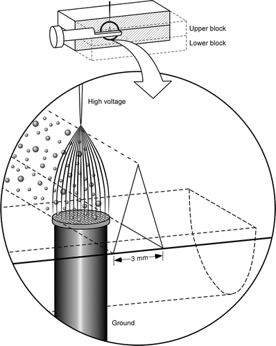
Another flow related issue is the relationship between flow channel geometry, the shape of the sampling volume and the shape of the electric field. Flow channel geometry was chosen after comparative testing of collection efficiency using flow profiles with cross sections that were circular, square, and triangular, of dimensions similar to the size of a typical collection substrate (TEM grid). The geometry that produced the best efficiency was the triangular cross section with a base width of 3 mm. This supported the hypothesis that a flow profile that closely contained the electric field would perform best. The current design thus incorporates a flow path that is triangular in cross section (). The flow path is fabricated by milling a V-groove in a solid block of CPVC that is mated with a second (flat) block to create the flow path. A channel is milled into the flat block to accept the “key” onto which the sampling media is affixed. The blocks are fastened together before the inlet and outlet are machined since those must be axisymmetric across the mating plane. The CPVC material was chosen for its low conductivity and permissivity and acts as an insulator to prevent the high voltage at the needle from leaking to a ground point. The aerosol in the region between the needle and the media holder thus becomes the ground path as the corona is initiated.
Other issues related to the flow field are diffusion losses, electrophoretic losses, and particle blow-by, i.e., particles at the periphery of the electrical field that either do not get charged or do not get fully entrained by the electrical field and thus pass through the sampling region without being collected. Our design minimizes the effects of diffusion losses by minimizing the residence time of aerosol in the sampler prior to collection and minimizes electrophoretic losses by not pre-charging particles as in some other designs (CitationDixkens and Fissan 1999; CitationFierz et al. 2007). Blow-by is minimized through the flow channel design and placement of the tip of the corona needle at the apex of the triangular cross section.
2.3. Corona Initiation and Ion Current
Sharpness of the anode needle was previously shown to be a critical ESP performance parameter at operating conditions of lower voltage and/or current (CitationCheng et al. 1981). To address this issue, our prototypes incorporated a robust but relatively sharp gold plated needle as an anode. To ensure it did not degrade over time, it was observed occasionally with a microscope and the EDS spectra of samples were examined for the presence of gold.
Cheng et al. also showed that efficiency was reduced at higher ion current. Since for that work, high ion currents were generated by increasing the voltage and because more recent results (CitationFierz et al. 2007) demonstrated the relationship between voltage (field strength) and particle trajectory, we hypothesized that the effect noted by Cheng et al. may have been partly due to the narrowing of the electric field lines within the sampling volume. We therefore changed the shape of the flow channel to accommodate a narrower electric field, which was aimed at obviating the potential collection losses due to narrowing of the field.
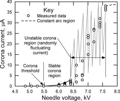
During operation of the prototype ESP, when voltage is applied to the corona needle via the solid-state high voltage generator, an electric field is created around the needle tip. The sharper the tip (smaller radius of curvature), the stronger the gradient of the electric field in the region around the tip. As the voltage to the needle is increased, the strength of the electric field eventually gets so high that it causes air molecules to ionize. This initiates a corona, made up of ions emitting from the region around the needle tip. We call this onset the “corona threshold” (). Further increase in voltage causes the ion concentration to increase and the corona may become visible to the naked eye. The ensuing flux of ionized air molecules or “ion current,” results in charging of the aerosol particles in the flow channel and they are subsequently accelerated toward the ground plate by the electric field. As the needle voltage is raised above the corona threshold, the ion current increases steeply with voltage potential and the ensuing increase in ion concentration in the collection region along with the stronger electric field, result in better particle charging and better collection efficiency. However, as voltage is raised above the corona threshold, the ion current becomes more and more unstable. This is due to the gap between the needle and the plate acting as a variable resistor that fluctuates based on temperature, humidity and the localized concentrations of ions and particles. There is thus a “transition region” of voltage, where the current is unstable (and pulses/surges at high frequency). The voltage at which this happens is dependent mainly on the gap distance. If voltage is raised still further the fluctuating current eventually stabilizes to a steady arcing as indicated by the dotted line in (this is akin to an arc welder). Since the power supply and high voltage generator in our ESP cannot withstand such high current, we discontinued tests before this level was reached.
For the tests of , the fluctuating current was measured indirectly using a digital oscilloscope, by monitoring the voltage drop across a small (100 kOhm) resistor placed in the grounding path. A series of capacitors were used to filter out the high frequency noise and the oscilloscope displayed the average voltage drop during each test which was then used to calculate an average current for that test. The collection efficiency during those tests was reduced for voltages above about 6.5 kV, as will be shown in section 3.3. A similar result was reported previously (CitationCheng et al. 1981) but the reason for reduced efficiency was not confirmed. It is our hypotheses that the surging of current and/or sparking allow the ions to follow a more narrow path to ground and also reduce the strength of the electrical field by reducing the voltage potential between the needle and collection plate. Both these effects would reduce the charging efficiency and thus the collection efficiency of the ESP. Avoiding sparking is also important because it can potentially damage the sampling media or result in creation of new particles as debris from larger particles or the sample media. To stabilize the ion current during operation, a resistor of approximately 25 mega-ohms was placed in the corona circuit and the operating voltage limited to about 6.3 kV.
2.4. User Interface
The operator interface on the current prototype comprises an LCD screen that displays menu choices accessed by the user via a keypad on the front panel. The most important parameter selected by the user is the sampling time (duration). In order to best estimate sampling time, the user should know the approximate concentration of particles in the air. Since not all users will have this information, a “cheat sheet” is provided and attached to the back of the ESP. The suggested sampling times were estimated by calculating the time needed to capture an ideal sample based upon the stated aerosol concentration, a flow rate of 55 cc/min, an assumed 85% collection efficiency and a desired average deposition spacing of approximately one micrometer between particles collected on the sample media. As an example, the suggested sampling time for an aerosol of 106 particles/cc is approximately 8 seconds.
2.5. Sampling Media and Basic Operation
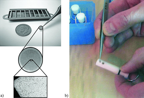
One of the primary design challenges was developing a method for inserting the TEM grid, or alternatively a thin metallic disk for SEM analysis, into the sampler. TEM grids are somewhat delicate (3 mm diameter and coated with films that are tens of nanometers in thickness) and require care when handling. They are typically stored in small slots in sealed, preferably static-free plastic boxes and handled with tweezers (). For ease of inserting the grids into the ESP under field conditions, we designed a removable “key” onto which a grid or foil disk media is attached. Tweezers are used to place the media onto the ground post of the key () and the media is subsequently affixed to the key (e.g., with a small piece of adhesive tape). This approach was chosen with the intent that such keys could be pre-loaded with sample media under lab conditions and taken to the field in a sealed case.
FIG. 4 (a) Tweezers are used to handle grids and a radiation source (background) helps to prevent static charge. (b) Sample media is placed onto the ground post of a key for use in the ESP (sealable case for keys in background).
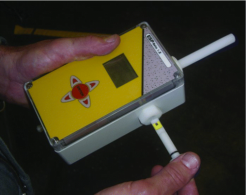
While the ESP was developed as a tool for aerosol characterization with the primary goals of maximizing particle collection efficiency and sample quality for subsequent EM analysis, the design also focused on portability and user friendliness. Several prototypes were built and tested and the results used to iteratively refine the design. The current pre-manufacturing prototype is shown in . The main features are the 5-key touch-pad user interface control, an LCD screen, user menus for sample setup, on-screen user feedback messages and insertable keys for loading the TEM grids or other sample media.
3. PERFORMANCE EVALUATION
The design goals for the ESP focused on the primary user needs, which are to get a “representative sample” in a timely manner, under field conditions. The performance criteria of most interest to the eventual end-user are thus collection efficiency and deposition uniformity. Tests were conducted to evaluate these parameters using well-characterized aerosols under laboratory conditions as described in the following paragraphs. The performance goals were for the ESP to have maximum collection efficiency and to produce samples that were uniformly loaded with particles, for optimum EM analysis.
3.1. Experimental Setup
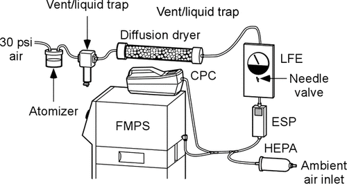
An experimental setup was designed to provide a source of well characterized aerosols that was constant and repeatable. The setup allows real-time evaluation of ESP collection efficiency using either a fast mobility particle sizer (FMPS) (model 3091, TSI Inc., St. Paul, MN) or a condensation particle counter (CPC) (model 3007, TSI Inc., St. Paul, MN). ESP samples of the lab-generated aerosols can be simultaneously collected onto TEM grids or other sample media during each test.
While conducting experiments, the aerosols are generated using an atomizer (), typically from dilute solutions of NaCl or KI in deionized water, producing micrometer sized droplets of the solutions. A portion of the aerosol is subsequently dried in a cylindrical diffusion dryer yielding a polydisperse aerosol of sub micrometer salt particles, while the excess is vented at atmospheric pressure. The particle size distribution of the dried aerosols is dependent on the solution concentration which is typically mixed to provide polydisperse aerosols with mean diameters in the 40–200 nm range. The sub micrometer aerosols are routed through the ESP at a pre-determined flow rate in the range of 40–200 cc/min, measured by a laminar flow element (LFE) and controlled by a needle valve. Since the FMPS and the CPC require flows greater than 200 cc/min, the aerosol exiting the ESP is diluted with HEPA-filtered air to provide the flow required for the instruments (). The dilution factor is calculated from the measured flow rates and used to correct the particle concentration measurements as needed to determine actual concentrations in the ESP during tests.
Using this setup, the “gross” collection efficiency of the ESP (fraction of particles removed from the flow) is determined by measuring the reduction in particle concentration while the ESP is on and dividing that number by the baseline concentration measured with the ESP off. As noted previously (CitationLaskin and Cowin 2002) this method of measurement may be subject to errors due to diffusion and electrophoresis. For this reason, additional measurements of “net” efficiency (fraction of particles deposited onto the sample substrate) were conducted as noted in section 3.2. For a typical measurement of gross efficiency, the concentration is first measured for a few minutes with the ESP off, then while measurements continued, it is switched on for about one minute, then off again for the remainder of the test. Since both instruments have relatively fast response time (1 s) versus the length of typical tests, the particle concentration values for “ESP on” and “ESP off” are taken as the average of tens/hundreds of individual measurements taken during the tests. The gross efficiency is then calculated using these average values.
3.2. Evaluating Collection Efficiency
In order to get a representative sample of an aerosol using an ESP collector, it would be optimal for the collection efficiency to be 100% and the particle deposition to be uniform across the surface of the sampling media, i.e., no sized-biased deposition. It has been shown (CitationFierz et al. 2007) that by modeling the theoretical deposition (for an axial flow ESP), and using empirical, size-dependent correction factors, it is possible to design an ESP that offers uniform deposition albeit at reduced collection efficiencies. In contrast, our approach is to try and demonstrate a technique which relies on high collection efficiency over a small surface area to provide quasi-uniform deposition onto the media over very short collection times. While it may provide a less uniform sample than the above method, such a technique would have the benefit of shorter collection times, which is an important advantage when taking field samples.
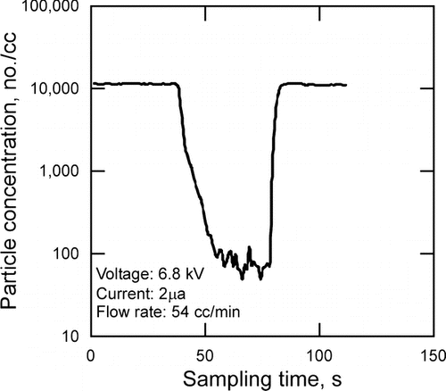
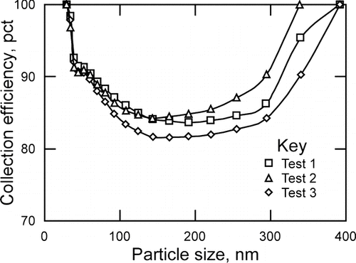
For most measurements of gross collection efficiency, the CPC was used, and logged data showed that the number concentration dropped suddenly when the ESP was powered on (). For some gross efficiency measurements, the FMPS was used, to allow real time measurements of both size distribution and total number concentration, at a sampling rate of 1 Hz. The measured efficiencies for the FMPS tests were similar to those measured using the CPC, but the measurable size range varies somewhat for the two instruments, so direct comparison of results is not made. Since the FMPS measures all “size bins” simultaneously (CitationTammet 1998), the data can be used to estimate the size-dependent collection efficiency (). The data for each curve in are from a single test run lasting about five minutes. The collection efficiencies were calculated for each FMPS channel and are averaged from a few hundred data records over the duration of a test. The data of indicate that for these operating conditions (100 cc/min flow and 6.4 kV corona voltage) the larger sub micrometer particles are collected very efficiently, that the collection efficiency drops off for smaller particles, reaching a minimum for particles in the 100–200 nm size range and that it improves for nanoparticles down to around 30 nm. This result is similar to that published previously (CitationCheng et al. 1981) and reflects the size dependent behavior of combined field and diffusion charging (CitationHinds 1999). Further experimental work is called for to elucidate the collection efficiency for smaller particles (< 30 nm). It is notable that nanoparticles are notoriously difficult to charge (CitationBaron and Willeke 2001) and it would be expected that collection efficiency would thus drop off steeply for particles smaller than about 30 nm.
FIG. 8 Size-dependent gross collection efficiency of NaCl particles, measured with the FMPS, for a prototype ESP similar to that in , operating at 100 cc/min flow rate and 6.4 kV corona voltage.
With the goal of comparing gross efficiency measurements with net efficiency values derived from ESP samples, a rudimentary procedure was used to estimate the net efficiency of collection. First, the total number of particles collected onto aluminum foil substrate samples was estimated by counting the number of particles per unit area on 8–10 SEM images from locations across the substrate. The average number per unit area from all the images was then multiplied by the deposition area to get an estimate of the total number of particles on the sample. The net efficiency was calculated as the ratio of this number of deposited particles divided by the maximum number of particles possible on the sample (derived from the flow rate, collection time, and the original aerosol concentration as measured by a CPC).
To compare gross and net efficiencies using this method, pairs of back-to-back tests were conducted using identical conditions, i.e., NaCl aerosols in the 40–300 nm size range at 55 cc/min flow rate and 6.4 kV corona voltage. For the first test of each pair, gross efficiency was measured with the CPC and for the second test, net efficiency was determined by SEM analysis of the collected sample. Results indicate that both gross and net efficiency have a similar correlation with ESP voltage, with variations on the order of 5–15% (). Such variations are not unusual for ESP tests. In addition to inherent variations in test conditions, the CPC-based efficiency measurements are potentially compromised by electrophoretic losses, while the EM-derived efficiencies are subject to error induced by non-uniform deposition across the sample media (since counting of every particle is unrealistic). The measurement or estimation of “true efficiency” is thus elusive.
FIG. 9 Comparison of gross and net efficiencies from back to back tests using the ESP of operating at 55 cc/min flow rate and 6.4 kV corona voltage.
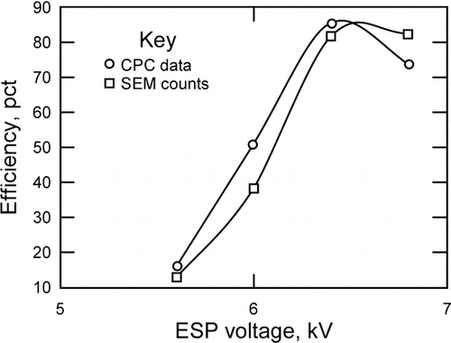
In addition to the deficiencies of the simplified counting method, there are other possible reasons why the EM-derived particle concentrations might not match those measured by the CPC or FMPS. One concern is that the absolute accuracy of particle sizers/counters is in question and there is no standard reference method for their calibration (CitationFierz et al. 2007; CitationRodrigue et al. 2007). There is also the possibility of particle losses within the collection system due to diffusion of particles onto surfaces of the flow channel or due to charged particles that blow-by or whose trajectories miss the sampling media but are caught by surfaces surrounding the media.
There are other potential reasons why the accurate measurement, modeling, or estimating of collection efficiency for ESP samplers is an elusive goal. As described previously (CitationFriedlander 2000), the roles of diffusion charging and field charging vary for different sized particles. They also vary as a function of corona strength, electric field strength, and geometry of the collection region. The method of efficiency measurement can also vary. It was shown previously that the combined uncertainties involved in efficiency estimation and measurement are quite high and that differences in aerosol concentration derived from ESP samples analyzed by TEM versus concentrations measured by a mobility particle sizer can be as high as 40%, primarily due to the statistical uncertainty of deposition uniformity (CitationFierz et al. 2007). For these reasons, published data on the collection efficiency of ESP samplers varies somewhat (CitationCheng et al. 1981; CitationLaskin and Cowin 2002; CitationFierz et al. 2007).
There are, however, commonalities in the data sets. For example, in the efficiency data of , we see a region of minimum collection between 100 and 200 nm, similar to that previously reported (CitationCardello et al. 2002). We also see an improvement in efficiency between about 30 and 100 nm as reported previously (CitationCardello et al. 2002; CitationFierz et al. 2007). In addition to these similarities there are also differences in the data. This is somewhat expected and is potentially due to the variations in design, including corona parameters and differences in geometries of the flow field, electric field, and operating parameters. Future research is warranted to further investigate efficiency optimization and measurement.
3.3. Optimizing Flow Rate and Corona Voltage
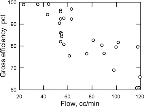
The experimental setup was used to investigate the influence of flow rate on collection efficiency. Results show a reduction in gross efficiency with increased flow () as reported previously (CitationCheng et al. 1981). While lower flow rates increase residence time and thus collection efficiency, there is a trade off between lower versus higher flow rate. While reducing the flow rate may improve collection efficiency, it can have the effect of depositing more particles near the leading edge of the sample substrate, which is undesirable since one of the goals is to have the particles well dispersed across the surface of the substrate for optimum analysis. Low flow rates also increase the potential for diffusion losses especially for small particles. On the other hand, if the flow rate is too high, residence time will be short and some particles may not gather enough electrical charge to offset their inertia and thus their trajectories will not end on the plate and they will not be collected.
FIG. 10 Gross efficiency (measured with CPC) versus flow rate for prototype ESP operating at 6.4 kV.
The experimental setup was also used to investigate the influence of corona voltage on gross collection efficiency (measured with the CPC), using an ESP operating at a flow rate of 55cc/min (). The data are based on 3–9 tests per voltage setting and suggest that collection efficiency improves in direct correlation with voltage up to approximately 6.8 kV and then begins to degrade. It is notable that the standard deviation among tests at each voltage setting is relatively large. This is reflective of the variability in ion current and field strength that is associated with the unstable nature of the gap resistance, compounded by factors such as temperature, humidity, flow rate fluctuations, particle concentration, media type, and media contact on the ground post. It is also notable that the transition after 6.8 kV parallels the steep increase in average ion current reflected in the data of . This supports the hypothesis that the higher and more fluctuating ion currents lead to reduced collection efficiency, possibly due to effects such as narrowing of the corona and fluctuations in the electric field.
FIG. 11 Gross collection efficiency (measured by CPC) versus corona voltage using the ESP of operating at 55 cc/min flow rate.
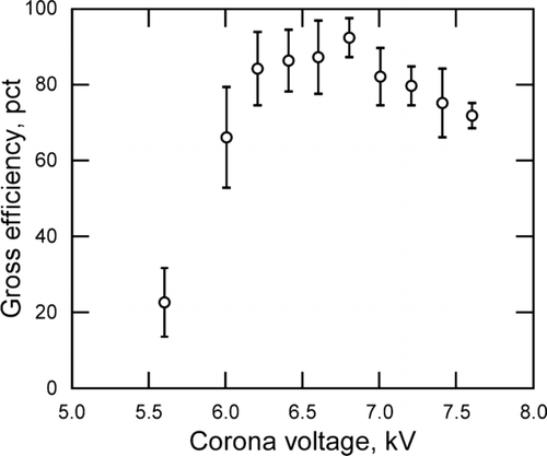
Comparing the data of to , all based on NaCl aerosols at 55 cc/min flow and similar levels of corona voltage, it is apparent that the gross and net efficiencies have a somewhat repeatable and similar trend, albeit a significant standard deviation. Given that no two tests are exactly the same and that both measurement methods have potential inaccuracies, the data suggest that for this prototype, expected collection efficiencies would likely be in the range of 76–94% at these operating conditions.
3.4. Deposition Uniformity
Uniformity of deposition and spacing of particles are especially important when attempting to use EM images to re-create particle size distributions and/or determine the relative concentration of various particle types in a given sample (CitationWhitehead and Leith 2008). Optimal deposition uniformity is that which results in no size-dependent deposition across the grid surface. Optimal particle spacing is that which insures that few, if any, particles are deposited such that they overlap on other particles. This is achieved by adjusting the sampling time to result in optimum loading of the sample media, such that particle spacing is on the order of a few times the diameter of typical particles. The deposition uniformity issue is more complex, since it involves several variables including particle charging rates, variations in electrical mobility of particles and size-dependent particle trajectories.
To assess the spacing and deposition uniformity, tests were conducted using NaCl polydisperse aerosol collected onto TEM grids and aluminum foil substrates. Results indicate that for properly selected sampling times, the spacing of sampled particles on the substrates is relatively even (). The density of deposited particles varies from highest at the upstream centerline of the flow path to lowest at downstream locations away from the centerline. The uniformity of deposition (spatial size-biased collection) on TEM grid samples was determined by counting and sizing particles on TEM images taken along the centerline at upstream, middle, and downstream locations. All “size bins” of the resulting particle size distributions were multiplied by a correction factor and then compared to the size distribution measured with the FMPS during the sample collection process (). The correction factor used was calculated as the ratio of maximum possible number of particles on the sample based on CPC data, flow rate, and collection time, divided by the number of particles counted.
FIG. 12 Examples of NaCl particle deposition onto: (a) TEM grid (b) aluminum foil media (SEM image).
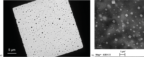
FIG. 13 Comparing particle size distribution of the original aerosol (FMPS measured) with results of TEM analysis of particles at upstream, center and downstream locations on the sample.
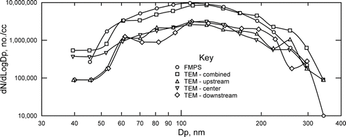
In the data of , it is apparent that there is a slight variation in the size distribution at the different locations, but that the combined data from all three locations matches reasonably well with the original particle size distribution. While the x-axis is labeled simply “Dp,” it is notable that the FMPS measures electrical mobility diameter while the EM-based data is derived from the average diameter of the 2-D cross sectional area of the particle images. This may in part explain the slight rightward shift of the EM-derived data compared to the FMPS data. These limitations not withstanding, the results suggest that the lower collection efficiency for some particle sizes (shown in ) does not affect the EM-derived particle size distribution significantly for this aerosol. Further research is needed to better understand, control and measure deposition uniformity and to use this information to optimize the ESP for collection of representative samples of polydisperse aerosols.
4. CONCLUSIONS
A handheld ESP particle sampler was designed, using previously published results to aid in optimization of collection efficiency and deposition uniformity. Results of sample analyses suggest that particle size distributions can be approximately reconstructed using images taken along the flow centerline at upstream, middle, and downstream locations. Using lab-generated NaCl aerosol at a flow rate of 55 cc/min and ESP corona voltage of 6.4 kV, gross collection efficiencies of 76–94% for particles in the 30–400 nm range were measured by the FMPS. Using the same aerosol, net deposition/collection efficiencies were determined by particle counts on SEM images and compared with measured gross efficiencies for a series of back to back tests using corona voltages in the range of 5.6–6.8 kV. The gross and net efficiencies both showed a similar correlation with ESP voltage, with variations on the order of 5–15%. Since similar or larger discrepancies have been reported for comparison of nanoparticle measurements made with different brands of particle sizers (CitationRodrigue et al. 2007), that level of accuracy may well be deemed acceptable by the industry.
It should be noted that not all aerosols are amenable to sampling with an ESP. Explosive atmospheres, for example, should obviously be avoided. When used for collecting volatile and semi-volatile materials, evaporation of particles/droplets may occur during sample handling or when exposed to the electron beam during electron microscopy analysis. In some cases this can be remedied by careful handling of samples and analysis with an “environmental” (low vacuum) electron microscope (CitationMiller et al. 2008). Another issue which must be considered is the potential for droplets or particles to undergo reactions during/after collection onto the TEM grid, especially at surface interfaces, including potential reactions due to ozone created by the corona. Some prior knowledge of the source aerosol will thus be advantageous in the effective use of this technique.
While further work to improve the quantitative analysis of ESP samples by EM is needed, this work is a significant step toward the potential routine application of single particle analyses to provide information regarding the properties of sampled aerosols. The handheld ESP addresses the need for a tool that can take samples quickly and effectively for assessment of ultrafine workplace aerosols. Beta versions of the handheld ESP are currently being evaluated with the goal of making this device commercially available.
This article not subject to United States copyright law.
The authors would like to thank Wayne Larson for his creative preliminary design work, the Gonzaga University student design team (Jason Graham, Elaine Markham, Alex Uffelman, and Dr. Steve Zemke) for developing the first prototype, Dallace Sevier and Franklin Bailey for their excellent EM work, and Dr. Mark Hoover of NIOSH-DRDS for his invaluable technical advice and encouragement.
REFERENCES
- Balbus , J. M. Maynard , A. D. 2007 . Meeting Report: Hazard Assessment for Nanoparticles—-Report from an Interdisciplinary Workshop . Environ. Health Perspect. , 115 ( 11 ) : 1654 – 1659 .
- Baron , P. A. and Willeke , K. 2001 . Aerosol Measurement—Principles, Techniques, and Applications. , New York : John Wiley & Sons, Inc. .
- Cardello , N. Volckens , J. 2002 . Technical Note: Performance of a Personal Electrostatic Precipitator Particle Sampler . Aerosol Sci. Technol. , 36 ( 2 ) : 162 – 165 .
- Cheng , Y. S. Yeh , H. C. 1981 . Collection Efficiencies of a Point to Plane Electrostatic Precipitator . Amer. Indust. Hygiène Assoc. J. , 42 ( 8 ) : 605 – 610 .
- Dixkens , J. and Fissan , H. 1999 . Development of an Electrostatic Precipitator for Off-Line Particle Analysis . Aerosol Sci. Technol. , 30 ( 5 ) : 438 – 453 .
- Evans , D. E. Heitbrink , W. A. 2008 . Ultrafine and Respirable Particles in an Automotive Grey Iron Foundry . Ann. Occup. Hyg. , 52 ( 1 ) : 9 – 21 .
- Fierz , M. Kaegi , R. 2007 . Theoretical and Experimental Evaluation of a Portable Electrostatic TEM Sampler . Aerosol Sci. Technol. , 41 ( 5 ) : 520 – 528 .
- Friedlander , S. K. 2000 . Smoke, Dust, and Haze: Fundamentals of Aerosol Dynamics. , New York : Oxford University Press .
- Gonzalez , D. Nasibulin , A. G. 2005 . A New Thermophoretic Precipitator for Collection of Nanometer-Sized Aerosol Particles . Aerosol Sci. Technol. , 39 : 1 – 8 .
- Hinds , W. C. 1999 . Aerosol Technology. , New York : John Wiley & Sons .
- Ibald-Mulli , A. Wichmann , H.-E. 2002 . Epidemiological Evidence on Health Effects of Ultrafine Particles . J. Aerosol Med. , 15 ( 2 ) : 189 – 201 .
- Kandlikar , M. Ramachandran , G. 2007 . Health Risk Assessment for Nanoparticles: A Case for Using Expert Judgment . J. Nanopart. Res. , 9 ( 1 ) : 137 – 156 .
- Ku , B.-K. and Maynard , A. D. 2005 . Comparing Aerosol Surface-Area Measurements of Monodisperse Ultrafine Silver Agglomerates by Mobility Analysis, Transmission Electron Microscopy and Diffusion Charging . J. Aerosol Sci. , 36 : 1108 – 1124 .
- Laskin , A. and Cowin , A. J. 2002 . On Deposition Efficiency of Point-to-Point Electrostatic Precipitator . J. Aerosol Sci. , 33 ( 3 ) : 405 – 409 .
- Leith , D. Leith , F. 1996 . Laboratory Measurements of Oil Mist Concentrations Using Filters and an Electrostatic Presipitator . AIHAJ , 57 : 1137 – 1141 .
- Maynard , A. D. 1995 . The Development of a New Thermophoretic Precipitator for Scanning Transmission Electron Microscope Analysis of Ultrafine Aerosol Particles . Aerosol Sci. Technol. , 23 ( 4 ) : 521 – 533 .
- Methner , M. Birch , M. E. 2007 . Identification and Characterization of Potential Sources of Worker Exposure to Carbon Nanofibers During Polymer Composite Laboratory Operations . J. Occupat. Environ. Hyg. , 4 : D125 – D130 .
- Miller , A. L. Habjan , M. C. 2008 . Available online at: http://www.acgih.org/store/ A Monograph of the ACGIH™ Air Sampling Instruments Committee: Microscopic Analysis of Airborne Particles and Fibers, ACGIH™, Cincinnati, Ohio (2008) 1–27
- Morrow , P. E. and Mercer , T. T. 1964 . A Point-to-Plane Electrostatic Precipitator for Particle Size Sampling . Amer. Indust. Hyg. Assoc. J. , 25 : 8 – 14 .
- Oberdoerster , G. 2001 . Pulmonary Effects of Inhaled Ultrafine Particles . Int. Arch. Occup. Environ. Health , 74 : 1 – 8 .
- Oberdorster , G. Maynard , A. 2005 . Principles for Characterizing the Potential Human Health Effects from Exposure to Nanomaterials: Elements of a Screening Strategy . Part. Fibre Toxicol. , 2 ( 8 ) : 1 – 35 .
- Rodrigue , J. Ranjan , M. 2007 . Performance Comparison of Scanning Electrical Mobility Spectrometers . Aerosol Sci. Technol. , 41 ( 4 ) : 360 – 368 .
- Tammet , H. , Mirme , A. and Tamm , E. 1998 . Electrical Aerosol Spectrometer of Tartu University . J. Aerosol Sci. , 29 ( Suppl 1 ) : S427 – S428 .
- Whitehead , T. and Leith , D. 2008 . Passive Aerosol Sampler for Particle Concentrations and Size Distributions . J. Environ. Mon. , 10 : 331 – 335 .
