Abstract
Electret filters are composed of thin, electrically charged fibers that are often utilized in industrial fields that require high collection efficiency with low flow resistance. A bundle-type electret filter in the Mechanical Ventilation and Air-Conditioning (MVAC) system of a Metro-subway was characterized in this study. The particle penetration and pressure drop parameters were examined under a filtration velocity ranging from 0.5 to 2.5 m/s. Particle penetration increased significantly in the early stages of filtration, but then became steady. The filter quality, which is a useful index of the filtration performance incorporating pressure drop and filtration efficiency, was evaluated for the test filters. The fiber bundle filter demonstrated a higher filter quality than the mechanical filter or the general panel-type electret filter with a small drop in pressure even at a high filtration velocity. In addition, the three dimensional structure and high electrostatic charge of the fiber bundle filter would enable a long retention time and constant level of pressure drop throughout the filtration.
NOMENCLATURE
| Δ P | = |
Pressure drop [Pa] |
| μ | = |
Air viscosity [Pa· s] |
| t | = |
Filter thickness [m] |
| U o | = |
Face velocity [m/s] |
| d f | = |
Fiber diameter [μ m] |
| α | = |
Packing density |
| P T | = |
Penetration rate |
| q F | = |
Filter quality [Pa–1] |
| λ | = |
Collection efficiency enhancement factor |
| M | = |
Mass loading [kg/m 2] |
| βTL | = |
Efficiency decay rate index [(kg/m2)–1] |
1. INTRODUCTION
Conventional fibrous filters that rely solely on mechanical action can only capture very small particles if their fibers are very thin and closely packed. However, a major disadvantage of this filter type is the high level of resistance imposed on the air flow that passes through. Electret filters that carry permanent electric charge primarily through the long-range electrostatic attraction of dust particles. These filters can be much looser than conventional fibrous filters, which causes less resistant to the air flow. In general, the collection efficiency of an electret filter is higher than that of a conventional fibrous filter, particularly for fine particles that are smaller than 1 μ m (Kanaoka and Emi 1984; CitationBaumgartner and Loffler 1986; CitationBarrett and Rousseau 1998; CitationWeeraya et al. 2006). Primitive devices are usually installed in indoor MVAC systems due to the need for simple operation and the treatment of large amounts of circulating air. Therefore, fine dust might not be collected by the filter, particularly during the initial filtration stage. The air quality in the Korean public subway has been a significant concern for the passengers and the government (Korea, MOE 2004). The national regulation of indoor particulate matter (PM) levels has become stringent and therefore, a variety of studies have been conducted in order to find a way to collect the fine dust from the tunnel and platform (CitationWang 2001; CitationTokarek et al. 2006; CitationKim 2008; CitationWan 2008). Therefore, we attempted to find the optimum filter medium for the MVAC system in the Metro subway in Seoul, Korea, in this study. This study consisted of a lab test and field examination that focused on the filtration efficiency and pressure drop across the filter media. In particular, the electret fiber bundle filter (FLIMMER filter, Sweden) has been intensively analyzed based on the efficiency index and filter quality.
2. MATERIALS AND METHODS
2.1. Test Materials
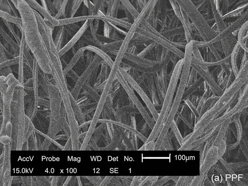
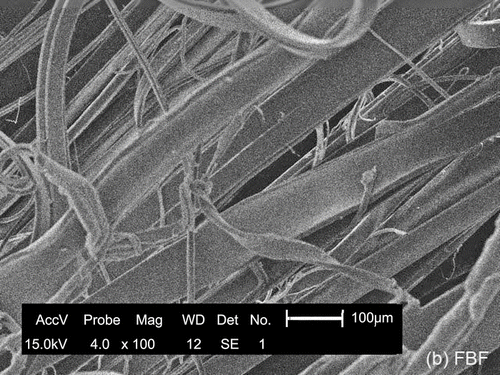
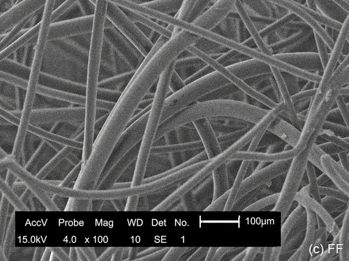
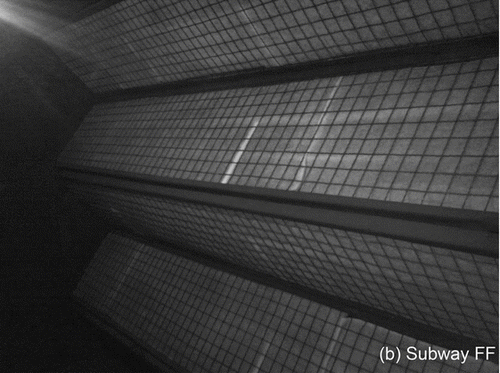
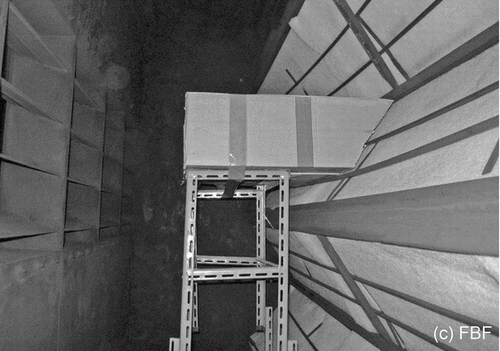
shows scanning electron microscopy (SEM) plates of the test filters. The electrically charged polypropylene filter (PPF) was procured from a local company (Daejung Ltd.). The fibrous filter (FF) was collected from the current MVAC system in the Seoul Metro-subway. Both the polypropylene filter and the fibrous filter are panel-type filters installed perpendicular to the main air stream. The fiber bundle-type filter (FBF) is comprised of a set of long thin electrically charged polypropylene fiber bundles that are supported by a body of multiple enlongated and flat laminae. The fiber threads are arranged mostly parallel to the air flow, which is in contrast to the other two filters.
Basic properties of the test filter media are summarized in . The packing fraction (α) of each filter was estimated by the empirical model of Davies (1973), represented by the following equations:
TABLE 1 Properties of the test filter media
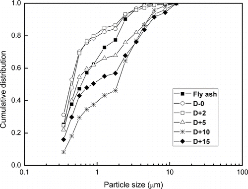
Fly ash from Boryung power plant was used as test dust, and was dried in a vacuum oven for 2 h at 105°C before being injected into the feed air stream. reveals the particle size distribution of test dust and the dust in a field MVAC room. They were measured by an optical aerosol spectrometer (Model 1.109, Grimm Aerosol Tech-nik, Ainring, Germany).
2.2. Experimental Method
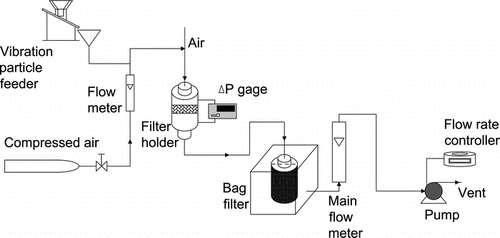
A schematic diagram of the experimental apparatus for the lab scale experiment is shown in . A vibratory feeder supplied the prepared dust into the filtration module (diameter: 50 mm), and the feed concentration was controlled at a range of 350 to 450 mg/m3 by varying the vibration intensity. The test filter was mounted on the filter holder, and the pressure drop across the filter medium was monitored at two pressure taps using a micromanometer (PLT-D5000Pa, ULFA Technology Co. Ltd.). A high-efficiency bag filter was fitted over the end in order to collect the fine particles that penetrated the filter media. Clean air was drawn through the filters using a suction blower. The filtration velocity was set in the range of 0.5 to 2.5 m/s, which was similar to the operation level of the air control system in the Metro-subway. The characterization properties for the filtration were areal weight, dust penetration, and pressure drop. The filters were examined periodically when they were loading dust. The actual replacing intervals for the filters depended upon the filter degradation in the field. summarizes the detailed experimental conditions for the particle loading test.
TABLE 2 Experimental conditions for the particle loading test
2.3. On-Site Evaluation of Filter Performance
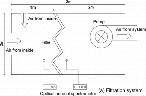
FBF was applied to the field MVAC room for the evaluation of practical performance. On the filter replacing day (2009.7.15), four FBF cells with different thickness (A-10 cm, B and C-14 cm, D-22 cm) were connected to the same 20 cm × 20 cm areas replacing FF in an MVAC of a subway station in Seoul (). Two optical aerosol spectrometers were used to measure the mass concentration of the dust particles in the upstream and downstream of the filter kit in real time for 15 ∼ 25 min. Filtration performance was evaluated based on the particle penetration (P m), as the equation
The face velocity across four FBF cells and MVAC FF wall was somewhat different with each other due to irregular turbulence near the filter cells but in the range of 1.5 to 2.5 m/s. Fresh filters were inserted on the morning of 15 July 2009. Then the long-term performance of FBF cells and FF in MVAC room were consistently evaluated until the next filter replacement day.
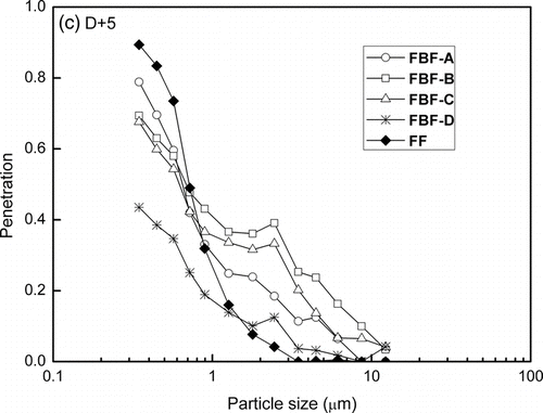
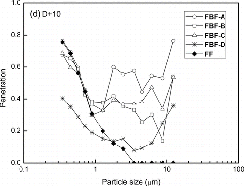
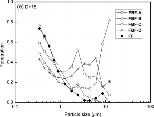
also shows the cumulative size distribution of particles in the upstream of the MVAC room in N-station. The D-0 (2009-7-15) means the day replacing with fresh FBF, and D+2 is two days after the replacing day, and also D+5, D+10, and D+15 are the days that five, ten, and fifteen days posterior to the replacing day, respectively. Results showed that the particles with diameter smaller than 1 μ m composed of the most part of the particles in the subway MVAC room. The concentration of particles smaller than 3 μ m accounted for 70% of the total particles concentration. Few particles larger than 3 μ m in diameter were present in the upstream from the test filters because relatively few of this size of particles resided in the ambient environment and because the pre-filters were effective at removing particles of this size. The fine mode particles are one of critical factors that the MVAC of Seoul Metro should focus on. Particles of this size come mainly from outside air and partly from the inner circulation of subway tunnel. The particles coming from outside with fresh air could be affected by weather and traffic condition.
3. RESULTS AND DISCUSSION
The filters with permanently charged fibers are called “electret” filters (CitationBrown et al. 1988; CitationBarrett et al. 1998). The dust-capturing mechanism of electret filters depends on a combination of electrostatic mechanisms (polarization and coulombic) and conventional mechanisms, including interception, impaction, and diffusion. The application of electrostatic forces can significantly augment the collection efficiency of fibrous filters. This method is particularly useful for improving the collection of particles in the size range of 0.05 to 0.5 μ m (CitationWang 2001; CitationLee et al. 2008a).
3.1. Basic Properties of Test Filters
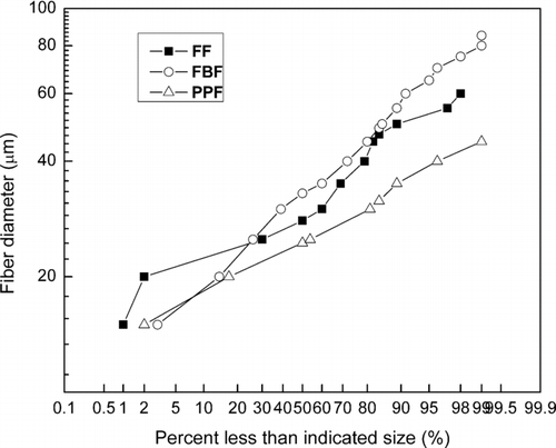
The mean fiber size and packing density specified in were determined from the plot of the log probability that is shown in . Based on the examination of the fibers using the SEM-EDX (SS-550, Shimadzu Corporation), the mean diameter of the test filter fibers was calculated from the log probability of 100 sample fibers (CitationHinds 1998) using the following equations:
The FBF is thick with an average size of 36 μ m and a relatively heavy specific weight. The calculated packing fraction of the FBF is the lowest compared to that of the other filter fibers, with a value of 0.01 due to its loose structure.
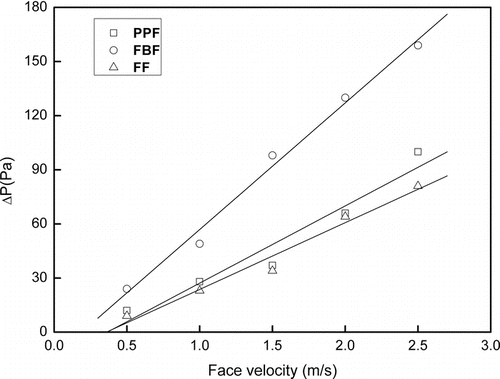
shows the pressure drop across the fresh samples of the test filters versus the face velocity. The pressure drop increases almost linearly with the face velocity, indicating a greater rate increase in the FBF than the FF and PPF. The pressure drop across the filter media is associated with its fiber diameter, packing density, and flow channel length (Davies 1973). Despite having a low packing density, the FBF shows a larger gradient of pressure drop with the flow velocity due to its thick module of 8.7 cm. The air stream flowing along the space channels encounters increase drag caused by the fiber bundles. The gradient of the pressure drop per unit filter thickness is 0.81 Pa·s·m-1/mm for the FBF, 42.8 for the PPF, and 3.7 for the FF. If the filter thickness is adjusted according to the field conditions, then the FBF can result in the least variation in the flow resistance. Therefore, the FBF is suitable for many applications with variable flow rates.
3.2. Pressure Drop and Penetration
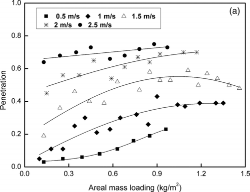
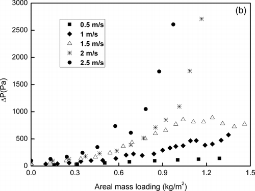
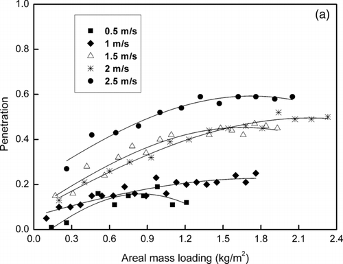
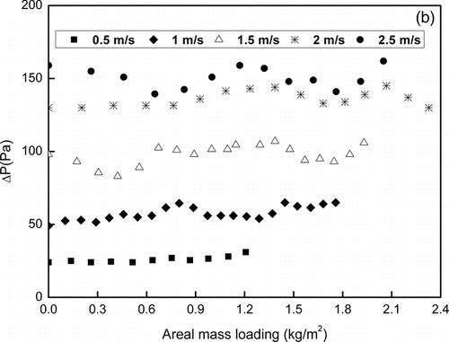
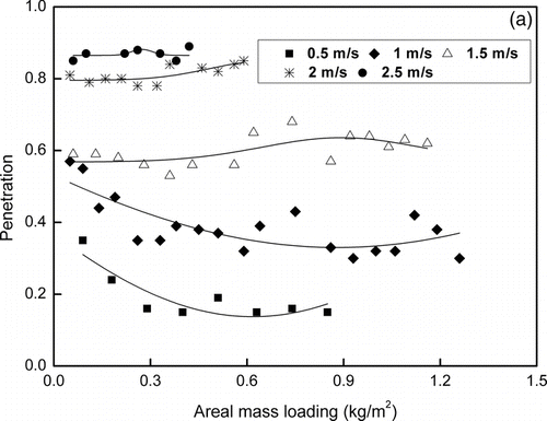
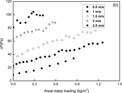
, , show the variations in particle penetration and pressure drop as a result of the dust filtration being carried out at different velocities. The direct indexes used to evaluate the filter performance are penetration and pressure drop. The particle penetration degree, P T, was determined using the following equation:
The face velocity has the least effect on the penetration in the FBF. High velocity leads to a high driving force, which could cause more particles to penetrate through the filter medium. Low filtration velocities leads to the formation of bridges of particles inside the filter medium due to low inertia levels and long retention time. The initial penetration level varies from 3% to 64% for the PPF and 35% to 85% for the FF, while the penetration levels are 1% to 27% for the FBF at each velocity. The smaller variation in the dust penetration levels with respect to the filtration velocity would be very advantageous for use in a large-scale filtration, since the variation in field flow may be irregular in certain ranges. The penetration rate of the dust becomes nearly constant as the filtration progresses after the initial variation. At relatively low velocities, 0.5 m/s to 1 m/s, the initial penetration levels of the two electret filters (PPF and FBF) are similar, but then FBF demonstrates a much lower penetration level than that of the PPF at the velocities of 2 m/s and 2.5 m/s. This result may have been due to the consistent particle precipitation along the long fiber thread by electrostatic force. For PPF, when particles are trapped within the fiber, they form the dendrite structure inside. Then the particles cause the gradual closing of the open channels, resulting in a greater overall pressure drop. Also PPF could demonstrate a higher potential capacity for capturing fine particles. However, there is no dust cake formed on the surface of FBF due to its unfixed filter frame structure. For the two kinds of electret filters, the electric drag forces on the particles tend to be weak in electret filters loaded with dust. This result is due to the neutralization of the charge on the fiber by the opposite charge on the captured aerosol particles (CitationBrown 1980). However, the layer of collected particles on the inside of the filter would capture the subsequent dust particles. Instead of diminishing the electrostatic forces, the mechanical interactions, including inertia and Van der Waals force, and direct screening enhance the particle capturing efficiency of the filters (CitationJi et al. 2003). The penetration levels eventually reach a steady state in which the decrease in the electrostatic force and the enhancement of the mechanical forces balance each other.
On the other hand, the filtration of the FF is dominated by a mechanical behavior, and a decrease in the penetration levels occurs at the low velocities of 0.5 and 1 m/s. Low filtration velocities could lead to more compact and systematic dust deposition on the filter surface which could reduce the dust penetration throughout the entire filtration time. However, the penetration fluctuates more or less at filtration velocities higher than 1.5 m/s, indicating that particles captured might be easily re-entrained subsequently as filtration proceeds.
The simultaneous deposition of particles by electrostatic charges on the surface and in the internal pore channels could cause a significantly more severe pressure drop after the early stages of filtration in the PPF. The absolute value of the pressure drop is particularly high at high flow velocities, more than ten times the values for the other filters. The configuration of the flat and thin panels leads to more surface filtration which results in the rapid formation of a thick dust layer. It could be concluded from these results that the PPF is not suitable for the current MVAC system in the Metro subway. The main filter mechanism of the FBF depends more on the electrical correlation, so dust particles are seldom deposited on the surface of the filter module. These results indicate that the dust cake does not play a role in the secondary separation of dust particles. Therefore, the nearly consistent pressure drop during the time of filtration could extend the life of the filter. The pressure drop across the FF gradually increases with an increase in the areal mass loading of the dust, and it is almost linear with the particle loading. Due to the loosely packed structure of FF, the dendrites are formed on the surface as well as inside of FF leading to a stable increase of the pressure drop. But the pressure drop at filtration velocities higher than 1.5 m/s shows more fluctuation, as the captured particles re-entrain into the main air flow.
3.3. Evaluation of Filter Quality
The filter quality of test filters indicates the dust collectability over the flow resistance. The filter quality, a useful index to assess dust filters, can be defined as the ratio of the logarithm of particle penetration per unit filter thickness to the pressure drop per unit thickness as first proposed by CitationHinds (1998) using the following equation:
The penetration (PT) could be evaluated using Equation (Equation7). The relative values of each filter under the same dust loading and flow velocity conditions can predict the filtration performance. In general, a good filter provides higher collection efficiency with a low pressure drop, which may result in a high level of filter quality.
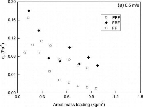
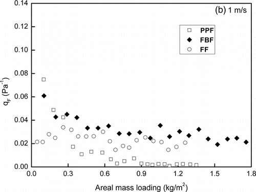
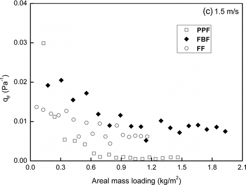
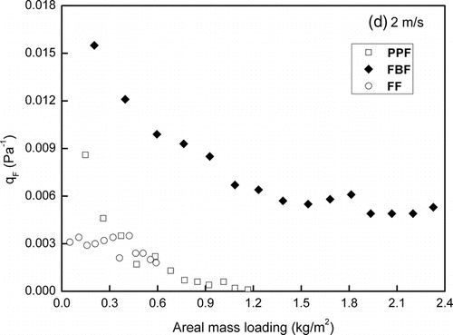
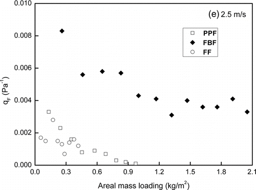
shows the variation in filter quality at different filtration velocities. The results show a logarithmic decease in the value of q F with the accumulation of dust on the filter media. The absolute value is high at low velocities, which is a common characteristic of many dust filters (CitationLee et al. 2008b). A lower velocity causes a low pressure drop without any significant particle penetration. The variation rate of the filter quality is relatively low for the FF, particularly in the early stage of filtration. The graphs (a) and (b) in indicate a slight increase in the filter quality of FF at low filtration velocities. The gas flow passes through a nearly fresh filter medium with little resistance and low penetration of particles is also observed in repeated tests. Upon reaching a value of approximately 0.12 Pa–1 at 0.3 kg/m2, the filter quality begins to decrease. The filter quality values are lower than those of the FBF throughout the filtration.
For FF filter, it is obvious that penetration levels are high during the initial filtration stage and, therefore, the filter becomes blocked due to dust loading. This blockage leads to a consistent decrease in the filter quality after the initial filtration stage. However, the penetration levels soon decrease, and the pressure drop remains almost constant, which allows the filter quality to become consistent. Even though it is desirable for the filter quality to remain constant throughout the filtration, it is not easy to achieve this ideal performance using mechanical filtration. The PPF has a lower specific weight, but exhibits a higher pressure drop than the other types of filters due to its denser structure. During the initial stage of filtration, the lower initial penetration with a moderate pressure drop results in high filter quality. The high packing density of the filter structure, as well as the electrostatic forces between the fiber and the particles, can enhance the particle collection. However, an increased collection efficiency rate does not always accompany the increase in the pressure drop. The filtration quality factor of the PPF decreases more rapidly than that of the other filter types as the filtration progresses.
The FBF is composed of deep and long fibers that looked like cilia, and the loose space consisted of the filter medium. Therefore, there is only a small increase in the rate of pressure drop due to particle capture. At the same time, the interaction between the incoming particles and the deposited particles forms the dendritic structure, but a dust cake barely forms on the filter surface. The deep filter module (8.7 cm) allows for long retention times for the dust particles. Therefore, the initial decrease in the filtration rate of the FBF is not as high as that of the PPF. As the particles filling the flow channels, the value of filter quality decreases to a certain level, which creates a balance between the increases of penetration and the pressure drop. Notably, the FBF apparently shows better filter quality at high filtration velocities than the other two kinds of filters. Above all, it is quite advantageous for the FBF to keep stable at high values of filter quality during the filtration.
3.4. Filtration Decay Rate of Dust-Loaded Electret Filters
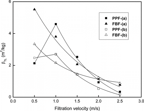
The filtration decay rate, βTL, is one of the indices specifically used to assess electret filters (CitationTanthapanichakoon et al. 2003). The value of the βTL introduced by Brown (1998) quantifies the extent of degradation of the filtration resulting from the loss of the electrostatic forces as the filtration progresses. The value of βTL is a constant, representing the initial electret filter performance, which depends primarily on the intrinsic filter material regardless of the filter thickness. A simple linear approximation, the βTL is only valid for the early stage of filtration. The definition of βTL is established based on the assumption that the filtration with high βTL values would be dominated by electrostatic forces, and as the value of βTL decreases, the dominant mechanism would shift from electrical adhesion to mechanical inter-forces. The value of βTL can be determined using the following equation:
The relative logarithmic ratio of penetration (P T(M L)) at a certain time during filtration to the penetration rate of a fresh filter (P T(0)) may not present a constant level with particle loading (M).
shows the value of βTL with the flow velocity at the areal mass loadings of a = 0.3 kg/m2 and b = 0.9 kg/m2. These results indicate that lower mass loadings lead to higher βTL values. A high feed concentration of dust leads to the early decay of the filter performance. In other words, a dilute dust flow phase is more easily influenced by electrostatic effects, but high filtration velocity deteriorates the electrical forces between the particles and the fibers. The FBF seems to be more stable depending on the flow velocity among the two test filters. In particular, the βTL of the FBF exceeds that of the PPF by over 2 m/s. Although the electrostatic intensity of the fiber is low in the FBF, the longer retention time could enhance the probability of electrical attachment of the particles. At 2.5 m/s, the decay rate, βTL, of the PPF approaches almost zero, which indicates that additional electrostatic collection could not be achieved past a certain level of dust loading. Therefore, the subsequent filtration is primarily carried out by inertia or diffusion.
3.5. Application of FBF to Subway MVAC
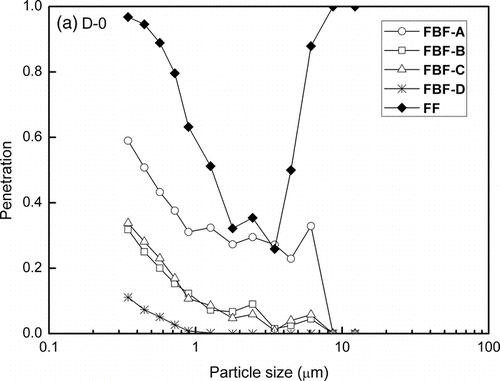
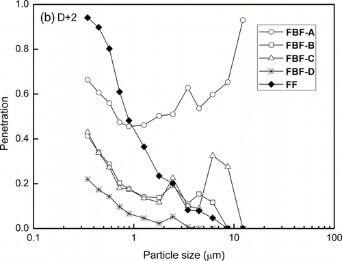
is the comparison of the penetration obtained from the field test for two kinds of filters at the subway MVAC room. It could be found that the FBF which are the same as the filter listed in , but just with different thickness (A-10 cm; B,C-14 cm; D-22 cm in thickness) show quite lower initial penetration for particles with diameter smaller than 1 μ m. The penetration in FBF has a proportional ratio to the filter thickness, and the cell with 10 cm filter shows the highest penetration for both fine particles and large particles. These results indicate that particles penetrate deeper into FBF filter. It could be found that for the filtration velocities used in conventional MVAC system, fine particles and particles larger than 10 μ m are captured in deeper layers of FBF filter. It implies that an optimal thickness of FBF is needed to perform the sufficient dust collection. As filtration proceeding, the particle penetration in FBF increases obviously, especially that of fine particles and particles larger than 1 μ m. This is in part due to the decay of electrostatic force during the filtration, and also partly attribute to the special three-dimensional structure of the filter which leads to re-bounce of the collected particles to the main airflow.
The penetration of fine particles reach stable level before long and the value is much higher, about 70% ∼ 80%. Penetration of the particles smaller than 1 μ m in FF does not obviously decrease with the filtration. Results show that the fresh FF has much higher penetration than used FF for particles larger than 1 μ m over the initial period. It may be because the sufficient space of the clean FF causes small particles to agglomerate. As particles collected on the filter, penetration of large particles in FF has decreased steeply due to the formation of dust cake on the filter surface. This is probably due to better particle capture by inertia impaction and interception mechanisms as the filters become loaded with particles. Therefore, FBF with high initial efficiency for fine particles less than 1 μ m could compensate the low efficiency of the current FF in the field station.
The efficiency data in figures exhibits more variable than the results found in controlled laboratory experiments. This discrepancy is not surprising because many factors cannot be controlled during field tests as precisely as the lab test. For example, the ambient particle size distribution changes from day to day. Thus, these fluctuations increase the variability of measurement in the filtration room. Few particles larger than 3 μ m in diameter are present upstream from the test filters.
4. CONCLUSIONS
In order to improve the low collection capability of the current filter system in an indoor MVAC system in Seoul's Metro-subway, the filtration quality of an electret fiber bundle filter was compared to that of two other commercial filters. The FBF seems to collect the fine particles primarily by electric forces rather than inertia or the screen effect. Therefore, dust cake does not build up perpendicular to the dust flow. Instead it forms the dendrites on the fibers which causing the primary resistance to the dust flow, and the resulting low pressure drop leads to an increase in the time between filter replacements in the MVAC system. As a result of this experiment, the electet filter (FBF) was determined to be advantageous for fine dust collection. In particular, pressure drop of the FBF, owing to thin and electrically charged threads, maintained consistentl at low levels throughout the filtration. Therefore, the dust collection capacity of the FBF is favorable for the subway MVAC system. In addition, the comparison of the filter quality, q F, and the decay rate, βTL, to the areal mass loading of dust particles also indicated that this filter can be well suited for the use of MVAC systems which treat a large volume of air. But the unstable collection efficiency for large particles and the increase of penetration with time are the main disadvantages for the FBF. Our further study will focus on resolving these disadvantages by other compensated methods such as applying an external electric field or consecutive layout of the filters.
Acknowledgments
This work is supported by Seoul R&BD program (CS070160).
REFERENCES
- Barrett , L. W. and Rousseau , A. D. 1998 . Aerosol Loading Performance of Electret Filter Media . Am. Ind. Hyg. Assoc. J. , 59 ( 8 ) : 532 – 539 .
- Baumgartner , H. P. and Loffler , F. 1986 . The Collection Performance of Electret Filters in the Particle Size Range 10 nm-10 μ m . J. Aerosol Sci. , 17 : 438 – 445 .
- Brown , R. C. 1980 . The Behavior of Fibrous Filter Media in Dust Respirators . Ann. Occup. Hyg. , 23 : 367 – 380 .
- Brown , R. C. , Gray , W. R. and Blackford , D. B. 1988 . Effect of Industrial Aerosols on the Performance of Electrically Charged Filter Material . Ann. Occup. Hyg. , 32 : 271 – 294 .
- Brown , R. C. 1993 . Air Filtration—An Integrated Approach to the Theory and Applications of Fibrous Filters , New York : Pergamon Press .
- Hinds , W. C. 1998 . Aerosol Technology—Properties, Behavior, and Measurement of Airborne Particles, , 2nd ed. , Malden, MA : Wiley-Interscience .
- Ji , J. H. , Bae , G. N. and Kang , S. H. 2003 . Effect of Particle Loading on the Collection Performance of an Electret Cabin Air Filter for Submicron Aerosols . J. Aerosol Sci. , 34 : 1493 – 1504 .
- Kanaoka , C. , Emi , H. , Otani , Y. and Iiyama , T. 1987 . Effect of Charging State of Particles on Electret Filtration . Aerosol Sci. Technol. , 7 : 1 – 13 .
- Kim , K. Y. , Kim , Y. S. and Roh , Y. M. 2008 . Spatial Distribution of Particulate Matter (PM10 and PM2.5) in Seoul Metropolitan Subway Stations . J. Hazard. Mater. , 154 : 440 – 443 .
- Lee , K. M. , Li , K. and Jo , Y. M. 2008a . Theoretical Study on the Electrostatic Effect Fir Aerosol Filtration . J. Korean Soc. Waste. , 26 ( 1 ) : 52 – 58 .
- Lee , K. M. , Lee , J. H. , Raper , J. and Jo , Y. M. 2008b . Assessment of Dust Filters by Filter Quality . Powder Tech. , 185 : 187 – 194 .
- Tanthapanichakoon , W. , Maneeintr , K. and Charinpanitkul , T. 2003 . Estimation of Collection Efficiency Enhancement Factor for an Electret Fiber with Dust Load . J. Aerosol Sci. , 34 : 1505 – 1522 .
- Tokarek , S. and Bernis , A. 2006 . An example of Particle Concentration Reduction in Parisian Subway Stations by Electrostatic Precipitation . Environ. Technol , 27 : 1279 – 1287 .
- Wang , C. S. 2001 . Electrostatic Forces in Fibrous Filters—a Review . Powder Tech. , 118 : 166 – 170 .
- Davies , C. N. , ed. 1973 . Air Filtration , London : Academic Press .
- Wan , G. J. , Sun , G. G. and Xue , X. H. 2008 . Solids Concentration Simulation of Different Size in a Cyclone Separator . Powder Tech , 183 : 94 – 104 .
- Weeraya , S. L. , Tanthapanichakoon , W. and Kanaoka , C. 2006 . Correlation for the Efficiency Enhancement Factor of a Single Electret Fiber . J. Aerosol Sci , 37 : 228 – 240 .
