Abstract
The presence of a cold surface in non-isothermal pipe flows conveying submicron particles causes thermophoretic particulate deposition. In this study, an analytical method is developed to estimate thermophoretic particulate deposition efficiency and its effect on overall heat transfer coefficient of pipe flows in transition and turbulent flow regimes. The proposed analytical solution has been validated against experiments conducted at Oak Ridge National Laboratory. Exhaust gas carrying submicron soot particles was passed through pipes with a constant wall temperature and various designed boundary conditions to correlate transition and turbulent flow regimes. Prediction of the reduction in heat transfer coefficient and particulate mass deposited has been compared with experiments. The results of the analytical method are in a reasonably good agreement with experiments.
NOMENCLATURE
| C | = |
Mean particle concentration (kg/m3) |
| C 0 | = |
Inlet particle concentration (kg/m3) |
| C L | = |
Outlet particle concentration (kg/m3) |
| C p | = |
Specific heat of the gas flow (J/kg K) |
| D | = |
Transient pipe diameter (m) |
| d p | = |
Particle diameter (m) |
| f | = |
Friction factor |
| h | = |
Convection heat transfer coefficient (W/m2K) |
| ID | = |
Inner diameter of a clean pipe (m) |
| Kn | = |
Knudsen number (= 2λ/d p ) |
| K th | = |
Thermophoretic coefficient |
| k d | = |
Deposit layer thermal conductivity (W/m K) |
| k g | = |
Gas thermal conductivity (W/m K) |
| k p | = |
Particle thermal conductivity (W/m K) |
| L | = |
Pipe Length |
| MW g | = |
Gas molar mass |
|
| = |
Mass flow rate (Kg/§) |
| Nu | = |
Nusselt number |
| Pr | = |
Prandtl number |
|
| = |
Heat transfer to the pipe wall (W) |
| R | = |
Gas constant (8.3143 J/mol K) |
| R g | = |
Specific gas constant (J/kg K) |
| R conduction | = |
Deposit conduction thermal resistance (K/W) |
| R convection | = |
Gas convection thermal resistance (K/W) |
| Re | = |
Reynolds number |
| Re t = 0 | = |
Initial Reynolds number for a clean pipe |
| T | = |
Gas temperature (K) |
| T 0 | = |
Gas inlet temperature (K) |
| T avg | = |
The average of inlet gas and the pipe wall temperatures (K) |
| T interface | = |
Deposit–gas interface temperature (K) |
| T L | = |
Gas outlet temperature (K) |
| T w | = |
Pipe wall temperature (K) |
| t | = |
Time (§) |
| U | = |
Mean gas velocity (m/s) |
| V th | = |
Thermophoretic velocity (m/s) |
| Greek | = | |
| Δ | = |
Deposit layer thickness (m) |
| ϵ | = |
Pipe effectiveness |
| η d | = |
Particulate deposition efficiency |
| λ | = |
Mean free path of a gas molecule (m) |
| μ | = |
Viscosity of the gas flow (kg/m s) |
| ρ | = |
Density of the gas flow (kg/m3) |
| ρ d | = |
Deposit layer density (kg/m3) |
| ρ p | = |
Particle density (kg/m3) |
| ν | = |
Gas kinematic viscosity (m2/s) |
1. INTRODUCTION AND LITERATURE
Particulate-laden flows are subject to many different forces including diffusion, turbulent impaction, thermophoresis, and electrostatic. Literature and experimental work show that thermophoresis is dominant among the aforementioned mechanisms for submicron particles.
This phenomenon occurs when a temperature gradient exists, forcing particles to move from a high temperature region to a lower one due to more vigorous collisions with gas molecules from the hotter region. This force arises from the fact that hotter gas molecules have higher velocity. Thus, in a thermal gradient the gas on the hot side of the particle hits with higher force than the gas from the cooler side, and a net force is created toward the cooler region like the pipe wall.
There are many industrial applications involved in thermophoretic particulate deposition including gas cleaning, prevention of particle deposition on silicon wafers of semiconductors, and heat exchangers. Accordingly, there have been many attempts to propose analytical correlations for thermophoretic soot particle depositions in laminar and turbulent pipe flows. Analytical solutions provide proportionality and functionality of variables especially for complex problems where many parameters are involved.
CitationRomay et al. (1998) studied the thermophoretic deposition of aerosol particles under laminar and turbulent pipe flows. They performed the experiment for variable gas inlet temperature, different particle sizes, and mass flow rates correlating to laminar, transition, and turbulent Reynolds numbers in a pipe flow. They proposed an analytical correlation for the deposition efficiency and compared it with other correlations in the literature (CitationByers and Calvert 1969; CitationNishio et al. 1974; CitationBatchelor and Shen 1985).
A steady-state model has been developed by CitationHousiadas and Drossinos (2005) to predict thermophoretic particle deposition in laminar and turbulent pipe flow. Their results suggest that the 1D boundary layer approximation in turbulent flow is adequate, in general. The 1D model and 2D Lagrangian model in their work provide the same level of accuracy until the gas to wall temperature difference is large. In that case, the 2D model shows significant improvements.
CitationHe and Ahmadi (1998) studied the thermophoretic deposition of particles in laminar and turbulent duct flows and compared the Brock-Talbot equation with the modified Cha-McCoy-Wood correlation. They also compared these two correlations with experimental measurements (CitationLi and Davis 1995a,b) for a wide range of Knudsen numbers. They also studied the dominant mechanisms of soot deposition for different Knudsen numbers.
Another effort in this field is the work done by CitationLin and Tsai (2003) for investigation of the thermophoretic deposition efficiency under developing flow at the entrance region. They found that the thermal entrance region of the pipe makes the thermophoretic deposition efficiency slightly higher than the fully developed case for a long pipe. They also developed empirical equations to predict thermophoretic efficiency of a laminar flow in a circular pipe in fully developed and developing flow under laminar flow conditions.
CitationLin (1976) developed an analytical procedure to predict the particle deposition efficiency by considering the thermophoretic velocity in the conservation equations of particles. Lin investigated the effect of significant parameters, including the temperature difference between the inlet gas and the wall, particle size, and Lewis number, on thermophoretic efficiency.
Although analytical correlations for thermophoretic particle deposition have been proposed before, the objective of our effort is to develop a novel correlation for cases where:
-
The pipe diameter reduction due to the deposit layer and thermal resistance of the deposit layer are taken into account in the solution
-
The layer properties are considered in the method based on experimental measurements
-
The proposed solution is applicable to longer exposure times compared to steady-state solutions previously reported in literature and accounts for time varying parameters
Our approach is to solve the energy equations for the bulk gas flow and the mass conservation of particles for a simple turbulent pipe flow with different boundary conditions including gas inlet temperature, wall temperature, gas mass flow rate, and inlet particulate concentration.
The Oak Ridge National Laboratory experiments employing engine exhaust gas in a controlled test set up are used to verify the proposed analytical solution of this study. Engine exhaust gas carries submicron soot particles and that makes it suitable for verification purposes of the analytical method. The exhaust gas was divided in a few pipes with designed Reynolds numbers to correlate transition and turbulent flow regimes.
The heat transfer coefficient (or effectiveness) of the pipe, and soot mass deposited along the pipe were compared to the experimental measurements for a relatively short exposure time (3 h). The comparison shows an acceptable agreement between the analytical solution and experimental measurements; however, there are still improvements to be considered.
Although this solution is compared with engine exhaust flows representative of diesel engine exhaust gas recirculation (EGR) coolers, it can be used in general for prediction of thermophoretic deposition of submicron particles in turbulent flows for a short exposure time.
2. GOVERNING EQUATIONS
In this part, the analytical method for thermophoretic particulate deposition in turbulent and transition pipe flows is described. Hot gas passes through the pipe that has a constant wall temperature. The schematic of the pipe is shown in . The pipe length (L), the inner diameter of a clean pipe (ID), the transient inner diameter due to particulate deposition (D(t)), the inlet temperature (T 0), the inlet concentration of particles (C 0), the interface temperature at the deposit–gas interface (T interface ), and the wall temperature (T w ) are depicted. Gas temperature (T), particle concentration (C), pipe diameter, heat transfer coefficient, and gas velocity are functions of time since this problem is a transient problem. By finding the transient diameter of the pipe, the conductive thermal resistance of the deposit layer and consequently the heat transfer coefficient (or effectiveness) drop of the pipe can be calculated.
The assumptions in developing the solution are:
-
Wall temperature is constant
-
The particles do not interfere with the flow properties due to their low mass fraction within the bulk gas
-
The radial variations of temperature and particle concentration in main equations (energy and concentration) are neglected compared to the axial changes
-
The bulk gas flow has low viscosity
-
The deposit layer has a uniform radial and axial distribution in the pipe and has a smooth surface (). The layer is not uniform in real experiments but this assumption is made to simplify the equations and it seems to give reasonable results that will be discussed later in this article.
2.1. Energy Equation for Bulk Gas
By neglecting the axial conduction in the gas phase (large Peclet number) and the transient term (quasi steady assumption), the convection heat transfer along the axis will be equal to the amount of heat that is transferred to the pipe walls (![]() ). Considering the thermal resistance of the deposit layer and the heat transfer to the wall, the energy equation for an elemental pipe segment (dx) can be written as:
). Considering the thermal resistance of the deposit layer and the heat transfer to the wall, the energy equation for an elemental pipe segment (dx) can be written as:
In the above equations, the convection thermal resistance of the gas flow (R convection ) and the conduction thermal resistance (R conduction ) of the deposit layer are taken into account. It is also assumed that the state variables (i.e., interface temperature, pipe diameter, gas velocity (U), density (ρ), specific heat (C p ), and gas convection heat transfer coefficient (h)) are not functions of x and they just vary with time (t). Constant values are considered for deposit properties. By integrating Equation (Equation2) along the pipe length, the temperature can be calculated as:
2.2. Particle Mass Conservation
Deposition is mainly due to thermophoresis for submicron particles. Neglecting the diffusion and other deposition mechanisms, the particle mass conservation in the pipe can be expressed as:
By reorganizing terms in Equation (Equation5) and introducing the definition for the thermophoretic velocity (V th ):
The thermophoretic constants AA,BB, CC, C s , C m , C t are 1.2, 0.41, 0.88, 1.147, 1.146, and 2.20, respectively (CitationTalbot et al. 1980).
For thermophoresis to occur, a temperature gradient in the radial direction is required. In turbulent flows, temperature and concentration variations in radial direction just occur in a thin layer near the wall. Hence, the temperature gradient can be defined by equating the heat fluxes at the interface of the deposit layer as:
The convection heat flux between the gas and the deposit interface must also be equal to the conduction heat flux through the deposit layer.
So, the interface temperature is:
Substituting the interface temperature and the temperature gradient in the particle concentration Equation (Equation7) results in:
Integrating Equation (Equation14) along the length (from 0 to x) yields:
Then, the particle deposition efficiency over the entire pipe length can be defined as:
2.3. Calculation of the Transient Pipe Diameter Due to Particulate Deposition
Particulates create a growing layer of deposits after landing on the pipe wall over time. Although the rate of deposition seems to be larger in the inlet compared to the outlet due to larger particulate concentration and larger driving force (temperature gradient), it is assumed that the layer is formed uniformly in the axial and radial directions in order to simplify the problem and make it solvable. Then the rate of mass deposition of the layer in terms of particulate deposition efficiency and particulate inlet concentration can be evaluated as:
Considering the deposit layer forming inside the pipe, Equation (Equation18) can be rewritten as:
Assuming that the bulk gas mass flow rate (![]() ) is constant over time and substituting the deposition efficiency, one obtains:
) is constant over time and substituting the deposition efficiency, one obtains:
The convective heat transfer coefficient and the velocity of the bulk gas flow are also functions of the transient pipe diameter. The heat transfer coefficient can be calculated from the Nusselt number (Nu) definition for fully turbulent pipe flows as (CitationIncropera and Dewitt 2002):
Since the Nusselt number in Equation (Equation21) is applicable for turbulent flows, its use in transient regimes may cause errors or deviations from experimental results. There is a modified version of the aforementioned Nusselt number that covers the transition region but it is not employed in this study for simplicity. The Reynolds number is defined by:
The reduction of the pipe diameter due to deposition changes the Reynolds number over time. For results presented later in this paper, Re t = 0 is defined to represent the Reynolds number for a clean pipe without the deposit layer as:
The friction coefficient (f) is a function of the pipe diameter, but the effect of the pipe diameter variation on f due to particulate deposition is small. Consequently, the variation of the friction factor with the pipe diameter (Reynolds number) can be neglected and f can be treated as a constant for the sake of simplicity.
The gas velocity is extracted from the continuity equation as:
Substituting all the definitions in Equation (Equation20) and some manipulation yield:
Equation (Equation26) is nonlinear and does not have an analytical solution unless some simplifications and assumptions are made. Accordingly, a Taylor expansion is employed for the exponential term as follows:
The first two terms in Equation (Equation28) are selected and the rest will be the error of this estimation. So, after simplifications Equation (Equation26) can be rewritten as:
Another Taylor expansion is utilized to estimate the power term in Equation (Equation29) as:
Since the criteria for using the proposed expansion are met, applying it simplifies Equation (Equation29) to:
Now, the ODE in Equation (Equation31) is linearized and can be integrated as:
After applying the initial condition D(t = 0) = ID, the result for the pipe diameter can be expressed as:
Taylor series expansion is used again to simplify the natural logarithmic term:
So, the result becomes:
Equation (Equation36) can be rewritten as:
Solving Equation (Equation37) results in three solutions for the transient pipe diameter, as follows:
Depending on the parameters and variables of the problem, the above set can give either three real numbers or one real number and two conjugate complex numbers. In each of the two cases, it is really trivial to detect the physically meaningful solution for the transient diameter so that it is not a complex or negative number, or larger than the clean pipe inner diameter (ID).
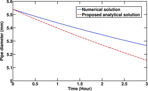
Due to the fact that non-linear terms are repeatedly expanded by Taylor expansions to first order terms for simplification of Equation (Equation26), a comparison is made with the numerical solution of Equation (Equation26) with the results presented in Equation (Equation39). shows how the transient pipe diameter is predicted by employing Taylor expansions. To perform a quantitative comparison some values are selected for critical parameters including inlet gas and the pipe wall temperatures, inlet gas pressure, and Reynolds number. It is seen that the linearized solution for the time-dependent pipe diameter is less than what numerical solution predicts. There is a small error percentage involved in calculation of the pipe diameter after 3 h (2.1%) and the difference between absolute values is (110 μm), which is quite small relative to the pipe diameter. But there is a large error (40%) in estimating the deposited particulate thickness predicted by the numerical solution (274 μm) and the analytical solution (384 μm) for a relatively long exposure time (3 h). This error cannot be avoided if an analytical solution is desired.
FIG. 2 Comparison between the numerical and analytical solutions of the transient pipe diameter. T 0 = 400°C, T w = 90°C, C 0 = 30 mg/m3,P 0 = 200Kpa, Re t = 0 = 10000.
Having the transient pipe diameter or the deposit thickness Δ = 1/2(ID− D(t)), the pipe effectiveness can be computed as:
2.4. Boundary Conditions
The inlet gas temperature, pressure, mass flow rate, inlet particle concentration, and pipe wall temperature are constant in each case. So, the boundary conditions for this problem are listed as:
-
 (0,t) =
-
T(0,t) = T 0
-
C(0,t) = C 0
-
P(0,t) = P 0
-
T | r = ID/2 = T w
3. TEST CASE FOR VERIFICATION OF THE SOLUTION
To verify the model, an experimental test case is required. One of the challenging issues in the diesel engine industry is dealing with particulate deposition in the coolers used to reduce the temperature of exhaust gas recirculation (EGR) that is used to control combustion temperature and nitrogen oxide emissions. Exhaust flow passing through the aforementioned coolers carries submicron particles and the flow is either in a transition or fully turbulent regime. Accordingly, such a particle-laden EGR engine flow is selected for verification of this solution.
The Oak Ridge National Laboratory has run EGR flow experiments in a controlled engine test set up. Details of the test set up and measurement procedures are fully described in CitationSluder et al. (2008). The exhaust gas was divided to a few pipes at different designed boundary conditions (). In all selected experiments, the pipe wall temperature was kept at 90°C to prevent water or hydrocarbon condensation in the pipe. Also, the gas inlet absolute pressure was kept at 196 Kpa.
TABLE 1 Boundary conditions for selected experiments
Hot gas flow passes through the pipe and the coolant circulates around it in the outer pipe to keep a constant wall temperature. The coolant temperature rise is negligible (∼ 2 o C). This low rise in coolant temperature is due to the large heat capacity of the coolant compared to that of exhaust gas flow.Footnote 1 The pipes are made of stainless steel that has a large thermal conductivity compared to that of soot and exhaust gas. After each time exposure (3 h), the sample pipes were removed from the fixture and analyzed.
Deposited soot layer properties are provided from the experimental data (CitationLance et al. 2009) to the model and listed in . Soot particle density and thermal conductivity are also listed in .
TABLE 2 Properties of the deposited soot layer
TABLE 3 Properties of soot particles
CitationMaricq and Harris (2002) showed that diesel engine soot agglomerate size ranges between 20 and 400 nm. They also showed that the mean particle size is 57 nm in most experimental conditions; hence, that is the number used to represent the particle diameter in this article.
3.1. Exhaust Gas Properties
It is noted that exhaust gas flow properties in the model are calculated at the average temperature of the inlet flow and the wall.
As a summary, the properties of the exhaust gas are listed here but more details of this calculation are presented in CitationAbarham et al. (2009).
4. RESULTS AND DISCUSSION
In this part, the results of the analytical approach are described and discussed. Before verification of the solution, a parametric study is done to highlight the effects of boundary conditions on thermophoretic particle deposition. For this parametric study, the geometry in and the aforementioned layer information are used. In each case, all boundary conditions except one were kept constant in order to magnify the effect of the varying boundary condition on particulate mass deposited. It is also noted that the unit of the particulate concentration is defined as kg per m 3 of the gas flow and not based on the particulates number.
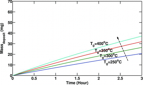
shows the effect of the gas inlet temperature on the amount of particulate mass deposited along the pipe. Increasing the inlet temperature while the wall temperature is constant results in increasing the thermophoretic driving force applied to particulates in the main flow. Also, increasing the inlet temperature decreases the gas density and increases the volumetric flow at a constant inlet pressure and the initial Reynolds number. Therefore, to have a constant particle concentration, the number of particles must be larger in a larger volumetric flow rate. As a result, the larger inlet temperature yields more deposited mass along the pipe over the selected exposure time (3 h) due to larger driving forces and number of particles.
FIG. 3 Variation of particulate mass deposited with gas inlet temperature (T 0). Re t = 0 = 10000, T w = 90°C,C 0 = 30 mg/m3,P 0 = 200 Kpa.
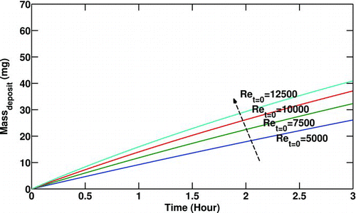
While the gas temperature and pressure are kept constant, gas properties do not vary. shows that by increasing the initial Reynolds number (gas mass flow rate) for a clean tube (defined in Equation (Equation23)), the deposit mass increases. This is due to the fact that a larger initial Reynolds number means a larger mass flow rate while the inlet temperature is constant (referring to Equation (Equation23)). A larger mass flow rate results in a larger volumetric flow for a constant inlet gas temperature (density). To satisfy the constant concentration constraint in this graph, the number of particles must be also larger. This results in larger deposition of particulate.
FIG. 4 Variation of particulate mass deposited with initial Reynolds number (Re t = 0). T 0 = 400°C, T w = 90°C,C 0 = 30 mg/m3,P 0 = 200 Kpa.
An expected trend is illustrated in . Increasing the inlet particulate concentration when the mass flow rate and the gas temperature are constant results in a larger mass deposited along the pipe due to the presence of more particles in the main flow.
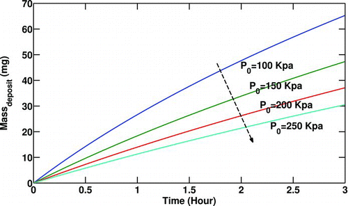
The effect of gas inlet pressure on deposited mass along the pipe is presented in . Increasing the inlet pressure increases the gas density while gas inlet temperature is kept constant. For a constant mass flow rate, increasing gas density lowers the volumetric flow rate. Thus the number of particles carried by the flow must be lesser to keep the particulate concentration constant. Therefore, a lesser inlet particulate number due to higher gas inlet pressure causes less particulate deposition.
FIG. 5 Variation of particulate mass deposited with particulate inlet concentration (C 0). Re t = 0 = 10000, T 0 = 400°C, T w = 90°C,P 0 = 200 Kpa.
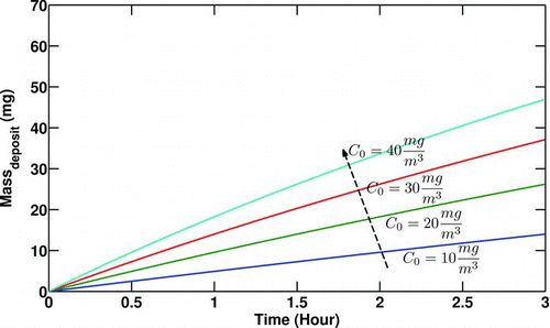
FIG. 6 Variation of particulate deposited mass with gas inlet pressure (P 0). Re t = 0 = 10000, T 0 = 400°C, T w = 90°C,C 0 = 30mg/m3.
To verify the solution, a comparison is also made with experimental measurements at different boundary conditions, as listed in . One set of boundary conditions (Experiment No. 8 in ) is selected for presenting the results. In the end, a comparison between the current model and experiments at various boundary conditions is made.
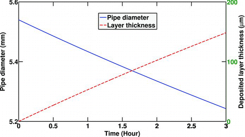
shows the diameter reduction of the pipe due to soot deposition and the deposit layer thickness for the selected experiment (No. 8). It can be seen that the layer thickness reaches approximately 150 μm which is quite a noticeable value.
FIG. 7 Pipe diameter reduction due to soot deposition and deposited layer thickness. Re t = 0 = 8000, T 0 = 380°C, T w = 90°C,C 0 = 30mg/m3,P 0 = 196 Kpa.
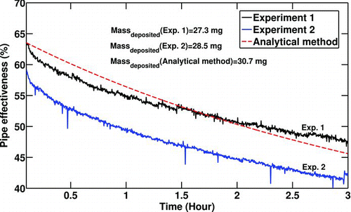
A comparison between the analytical solution and experimental results (No. 8) for the effectiveness of the surrogate pipe is shown in . The experiments were run twice for the statistical confidence. The differences between the experiments (especially at t = 0) is due to errors in measurements, specifically the exhaust mass flow rate or temperature differential. The analytical solution predicts the effectiveness drop of the surrogate pipe reasonably well in terms of both magnitude and slope. That is, the rate of heat transfer reduction of the pipe over time is predicted reasonably well by the equations. The effectiveness of the cooler degrades 17% as a result of deposit formation. Although this case is the worst case for deposition since it has the highest inlet temperature and inlet soot concentration with a high initial Reynolds number, this amount of degradation is quite significant. This is why this problem is getting more attention in industrial applications especially automotive industry. Soot particle mass deposited for each experiment and the analytical solution are also shown in . The numbers show a reasonable consistency between the experimental measurements.
FIG. 8 Comparison of effectiveness vs. time. Re t = 0 = 8000, T 0 = 380°C, T w = 90°C,C 0 = 30mg/m3,P 0 = 196 Kpa.
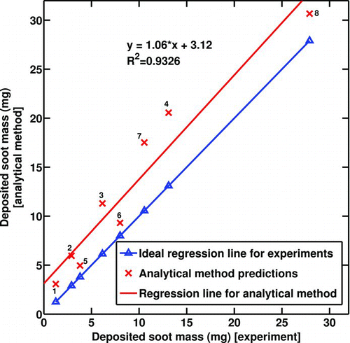
shows the deposited soot mass predicted by the analytical solution versus the deposited soot mass measured experimentally for all 8 cases. The values plotted for the experimental results represent the average recorded between the two runs that are almost identical in most cases. If the analytical method predicted the mass gain exactly the same as the experimental results, the dotted regression line would have been achieved; however, the other regression line is what the current analytical solution predicts.
FIG. 9 Deposited soot mass gain—model results vs. experimental measurements. Numbers on the data points indicate experimental conditions from .
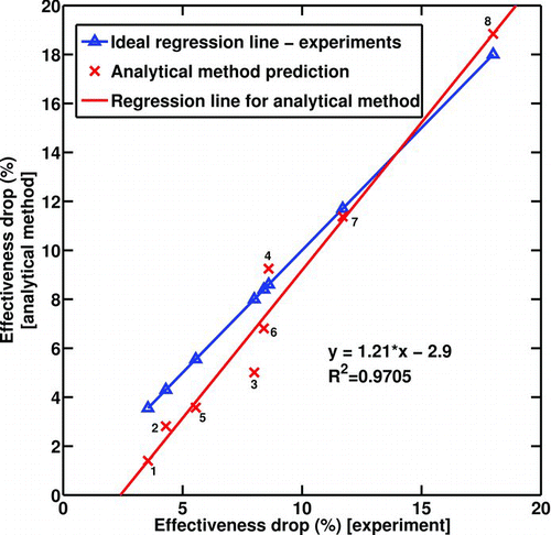
demonstrates the same comparison for the effectiveness drop. Four experiments (No. 1 to 4 in ) have initial Reynolds numbers (Re t = 0) between 4000 and 4500; however, the last four experiments (No. 5 to 8 in ) are conducted for initial Reynolds number between 8000 and 9000. The results of the analytical solution in the graph are labeled with the corresponding experiment number. There could be several reasons for the discrepancies observed between the solution and experiments. The deposit layer properties, including thermal conductivity and density, are important parameters that affect the results significantly. When the deposit layer grows, the interface temperature is hotter and the layer properties may be a function of the interface temperature and the layer thickness. In this model, the deposit layer properties are non-varying with temperature. Possible chemical reactions in the deposit layer could be a reason although they are not expected to be important in these short exposures. The deposit layer is a highly porous medium with a 98% of porosity (CitationLance et al. 2009). There could be a convective heat transfer mechanism occurring inside the layer at such high porosity. More experimental measurements are required to clear these ambiguities.
5. CONCLUDING REMARKS
An analytical solution for thermophoretic deposition of submicron particles in transition and turbulent flow regimes is proposed. An explicit function is offered for the deposited layer thickness (the transient pipe diameter).
A parametric study is conducted to investigate the effect of boundary conditions on the amount of particulate mass deposited. It was shown that larger gas inlet temperature, inlet particulate concentration, and initial Reynolds number result in larger particulate mass deposited, while larger gas inlet pressure reduces it when all other boundary conditions are kept constant.
The heat transfer coefficient degradation of the pipe over time due to particulate deposition is also predicted as a consequence of the diameter estimation. Particulate deposition can degrade heat transfer effectiveness of a surrogate pipe significantly even in a short exposure time (3 h). Also, the proposed correlation for the particle deposition efficiency shows that it is a function of the transient pipe diameter and varies as the layer grows.
Predicted effectiveness drop and soot mass deposited have been compared with data from experiments run at Oak Ridge National Laboratory for particle-laden engine exhaust flowing through a heat exchanger with controlled conditions. The results of the analytical approach are in reasonable agreement with experimental measurements.
Notes
1A constant wall temperature is an appropriate assumption in diesel engine EGR coolers since the liquid coolant temperature typically changes only a few degrees across the cooler, and the coolant-to-metal thermal resistance is much less that the gas-to-metal.
REFERENCES
- Abarham , M. , Hoard , J. , Assanis , D. , Styles , D. , Curtis , E. , Ramesh , N. , Sluder , S. and Storey , J. 2009 . Numerical Modeling and Experimental Investigations of EGR Cooler Fouling in a Diesel Engine SAE World Congress & Exhibition, Detroit, SAE 2009-01–1506
- Batchelor , G. K. and Shen , C. 1985 . Thermophoretic Deposition of Particles in Gas Flowing over Cold Surfaces . J. Colloid Interface Sci. , 107 : 21 – 37 .
- Byers , R. L. and Calvert , S. 1969 . Particle Deposition from Turbulent Streams by Means of Thermal Force . I EC Fundam. , 8 : 646 – 655 .
- He , C. and Ahmadi , G. 1998 . Particle Deposition with Thermophoresis in Laminar and Turbulent Duct Flows . Aerosol Sci. Technol. , 29 : 525 – 546 .
- Housiadas , C. and Drossinos , Y. 2005 . Thermophoretic Deposition in Tube Flow . Aerosol Sci. Technol. , 39 : 304 – 318 .
- Incropera , F. P. and Dewitt , D. P. 2002 . Heat and Mass Transfer, , 5th ed , 491 – 492 . New York : John Wiley & Sons .
- Lance , M. , Sluder , C. S. , Wang , H. and Storey , J. 2009 . Direct Measurement of EGR Cooler Deposit Thermal Properties for Improved Understanding of Cooler SAE World Congress & Exhibition, Detroit, SAE 2009-01-1461
- Li , W. and Davis , E. J. 1995a . Measurement of the Thermophoretic Force by Electrodynamics Levitation: Microspheres in Air . J. Aerosol Sci. , 26 : 1063 – 1083 .
- Li , W. and Davis , E. J. 1995b . The Effects of Gas and Particle Properties on Thermophoresis . J. Aerosol Sci. , 26 : 1085 – 1099 .
- Lin , J. S. and Tsai , C. J. 2003 . Thermophoretic Deposition Efficiency in a Cylindrical Tube Taking into Account Developing Flow at the Entrance Region . J. Aerosol Sci. , 34 : 569 – 583 .
- Lin , S. H. 1976 . Particle Deposition due to Thermal Force in a Tube . Appl. Sci. Res. , 32 : 637 – 647 .
- Maricq , M. and Harris , S. 2002 . The Role of Fragmentation in Defining the Signature Size Distribution of Diesel Soot . J. Aerosol Sci. , 33 : 935 – 942 .
- Nishio , G. , Kitani , S. and Tkahashi , K. 1974 . Thermophoretic Deposition of Aerosol Particles in a Heat-Exchanger Pipe . Ind. Engng Chem. Des. Develop. , 13 : 408 – 415 .
- Romay , F. J. , Takagaki , S. S. , Pui , D. Y. H. and Liu , B. Y. H. 1998 . Thermophoretic Deposition of Aerosol Particles in Turbulent Pipe Flow . J. Aerosol Sci. , 29 : 943 – 959 .
- Sluder , C. S. , Storey , J. , Lewis , S. , Styles , D. , Giuliano , J. and Hoard , J. 2008 . Hydrocarbons and Particulate Matter in EGR Cooler Deposits: Effects of Gas Flow Rate, Coolant Temperature, and Oxidation Catalyst SAE Powertrain, Fuel & Lubricant Meeting, Rosemont, SAE 2008-01-2467
- Talbot , L. , Cheng , R. K. , Schefer , R. W. and Willis , D. R. 1980 . Thermophoresis of Particles in a Heated Boundary Layer . J. Fluid Mech. , 101 : 737 – 758 .

