Abstract
Large-eddy simulations (LES) of particle transport and deposition in turbulent channel flow were presented. Particular attention was given to the effect of subgrid scales on particle dispersion and deposition processes. A computational scheme for simulating the effect of subgrid scales (SGS) turbulence fluctuation on particle motion was developed and tested. Large-eddy simulation of Navier-Stokes equations using a finite volume method was used for finding instantaneous filtered fluid velocity fields of the continuous phase in the channel. Selective structure function model was used to account for the subgrid-scale Reynolds stresses. It was shown that the LES was capable of capturing the turbulence near wall coherent eddy structures.
The Lagrangian particle tracking approach was used and the transport and deposition of particles in the channel were analyzed. The drag, lift, Brownian, and gravity forces were included in the particle equation of motion. The Brownian force was simulated using a white noise stochastic process model. Effects of SGS of turbulence fluctuations on deposition rate of different size particles were studied. It was shown that the inclusion of the SGS turbulence fluctuations improves the model predictions for particle deposition rate especially for small particles. Effect of gravity on particle deposition was also investigated and it was shown that the gravity force in the stream wise direction increases the deposition rate of large particles.
1. INTRODUCTION
Analyzing transport and deposition of aerosols suspended in air streams has attracted considerable attention in the past two decades. Particle transport and deposition plays a major role in a number of industrial and environmental processes. Filtration and separation processes, combustion, air and water pollution, electrophotography machines, targeted pharmaceutical drug delivery, and lung deposition are just a few examples. Particulate micro-contamination is also of great concern in microchip fabrication industries. With the size of feature reaching the nanometer range, small particle deposition has become the main cause of defects and loss of yield in microelectronic industries.
Extensive experimental and computational studies related to particle transport in turbulent flows have been reported in the literature (Hinze 1982; Hinds 1975; CitationWood 1981; CitationPapavergos and Hedley 1984; CitationAhmadi 1993). Accordingly, small particles are transported by the instantaneous fluid velocity field. Thus, for computer simulation of particle transport, dispersion, and deposition processes, the instantaneous flow velocity should be carefully evaluated.
Using Reynolds averaged Navier-Stokes (RANS) equations with the aid of a turbulence model for finding the mean flow has been the most common approach, particularly for practical applications. In this approach, the instantaneous turbulent fluctuating velocity fields are simulated separately, using a stochastic method, and are added to the mean flow that are evaluated via a RANS model. This approach is inevitably inaccurate as it treats turbulence fluctuation as a Gaussian random field, and therefore, is incapable of capturing the turbulent coherence structures. The most accurate available approach for evaluating instantaneous velocities is the direct numerical simulation (DNS) of Navier-Stokes equations with a high-resolution grid that resolved the Kolmogorov scale of turbulence. Despite its accuracy, applications of the DNS method have been limited to flows in simple passages at low Reynolds numbers. This is because the sharp increase of the computation cost of DNS with flow Reynolds number. Large Eddy Simulation (LES) approach was developed because of its lower computational cost compared to DNS so that it can handle high Reynolds number flows with reasonable accuracy. In LES method, the large energy containing scales of turbulence are resolved, while the effect of scales of turbulence smaller than the grid size is modeled by using a so-called subgrid scale model. Thus, LES is less sensitive to modeling errors in compare with RANS models, since subgrid scales contain much lower energy than the large scales.
Direct numerical simulations (DNS) of particle deposition in wall-bounded turbulent flows were performed by CitationMcLaughlin (1989). Ounis et al. (Citation1991, Citation1993), CitationBrook et al. (1992), and CitationPedinotti et al. (1992)used DNS to studies the vortical structures and particle transport in the turbulence wall regions. These studies were concerned with providing an understanding of particle deposition mechanisms in turbulent flows. Recently, CitationZhang and Ahmadi (2000) studied aerosol deposition from turbulent air streams in vertical and horizontal ducts using the DNS approach. They showed that the particle-to-fluid density ratio, the shear-induced lift force, the flow direction relative to gravity, and the shear velocity affect the particle deposition rate. Furthermore, the effect of gravity and its direction on the particle deposition rate becomes more significant at low shear velocities.
LES has also been used for particle transport analysis in the last decade. In earlier applications of LES, however, just the filtered velocity that contains the resolved scale of turbulent was used for particle trajectory analysis and the contributions of subgrid scales were ignored (CitationVance and Squires 2006; CitationUijttewaal and Oliemans 1996; CitationWang and Squires 1996; CitationYeh and Lei 1991). Recently, however, more attention was given to the effect of subgrid scale fluctuations on particle transport. CitationArmenio et al. (1999) investigated the effect of disregard the subgrid scale fluctuation on particle motion by comparing the DNS and the LES. They observed certain differences between the DNS and LES prediction especially when a significant percentage of the fluctuation energy is in unresolved part. They also showed that inertia particles are less sensitive than tracer particles to subgrid scale fluctuations in the LES approach.
Including the effect of subgrid scale fluctuations on particle motion was addressed by a few researchers in literature. CitationWang and Squires (1996) solved a transport equation for the SGS kinetic energy and obtained the corresponding SGS intensities using the same relative magnitudes as the resolved scale intensities. Then they generated the SGS fluctuation velocities using the computed intensities scaled by random numbers sampled from a Guassian distribution. They used the sum of the filtered velocity and the subgrid scale fluctuating velocity for computing the particle trajectory analysis. It, however, is known that the use of simple scaled random numbers will lead to dispersion that will depend on the computational time scale.
CitationKuerten (2006) and CitationShotorban and Mashayek (2005) reconstructed the instantaneous velocities from the filtered ones by an approximate deconvolution model. CitationKuerten (2006) studied turbophoresis process and particle velocity fluctuations near the wall in channel flow. CitationShotorban and Mashayek (2005) showed improvement in particle–phase statistics using this method.
The present study is concerned with developing a computational model for studying the effect of subgrid scale turbulence fluctuations on particle dispersion and deposition processes. LES of the Navier-Stokes equations in a turbulent channel flow was performed and the filtered instantaneous velocities were evaluated. Subgrid scale Reynolds stresses are modeled by using Selective Structured Function model of CitationMétais and Lesier (1992) and CitationDavid (1993). The instantaneous subgrid scale velocity fluctuations were simulated using Kraichnan's (1970) Gaussian random field model scaled with the appropriate SGS intensities. Transport and deposition of particles of different sizes was studied using the Lagrangian particle tracking approach. The drag, lift, Brownian, and gravitational forces were included in the particle equation of motion. The Brownian excitation was simulated as a white noise process.
A series of one-way coupled simulations were performed and the deposition rate of particles in the size range of 1 to 130 μ m was studied. The importance of subgrid scale fluctuations on the deposition rate of different size particles was assessed. The effect of presence of gravity on particle deposition is also studied. The simulation results show that the inclusion of subgrid scale fluctuation significantly affects the deposition rate of small particles.
2. LARGE EDDY SIMULATION (LES) OF TURBULENT FLOW FIELD
The instantaneous filtered fluid velocity field in the channel is evaluated by LES of the Navier-Stokes equation. Filtering operation is introduced to decompose the dependent variables, f, into the sum of a filtered (or resolved) component, ![]() , and a residual (or subgrid-scale) component, f′. A typical filtering operation for any variable f (x
i
,t) is given as (Lesier and Métais 1996),
, and a residual (or subgrid-scale) component, f′. A typical filtering operation for any variable f (x
i
,t) is given as (Lesier and Métais 1996),
The application of the filtering operation to the continuity and Navier-Stokes equations gives
The effect of unresolved scales on the resolved part of turbulence appears in the subgrid scale (SGS) Reynolds stress tensor, τ
ij
= ū
i
ū
j
− ![]() i
u
j
, which is modeled using the eddy-viscosity hypothesis. That is,
i
u
j
, which is modeled using the eddy-viscosity hypothesis. That is,
Equation (Equation3) then becomes,
A channel with length of L = 30 cm, height of H = 10 cm, and width of W = 20 cm was used in the simulations. A kinematic viscosity of ν = 2× 10− 5 m 2/s and mean velocity of 2.4 m/s are used in the analysis. The Reynolds number based on half of the channel height (h = H/2) and friction velocity (u*), Reτ = u* h/ν is about 350. (The corresponding Reynolds number based on the mean velocity and hydraulic diameter is 24,000.) No-slip boundary conditions at the channel walls and periodic boundary conditions in the streamwise and spanwise directions were imposed. A computational grid of 41× 77× 81 was used in the simulation. The grid spacing in x and z directions are constant with Δ x + = 52.5,Δ z + = 17.5, where x + = xu*/ν is in wall units. In the y-direction (perpendicular to the wall), however, there was a contraction toward the wall with the nondimensional distance of the first grid point from the wall being Δ y wall + = 0.77.
3. PARTICLE EQUATION OF MOTION
The equation of motion of a spherical particle is given as
Here u′ SGS i is SGS fluctuation velocity. It should be emphasized that with the use of instantaneous fluid velocity field in Equation (Equation8), the interaction of particle with the local turbulence is accounted for.
In Equations (Equation8) and (Equation9), x i is the particle position, t is time, d is the particle diameter, S is the ratio of particle density to fluid density, g i is the acceleration of body force, K = 2.594 is the constant coefficient of Saffman's lift force, n i (t) is the Brownian force per unit mass, and Re p = |u i − u i p |dν is the particle Reynolds number based on the flow-particle slip velocity and the fluid kinematic viscosity, and τ is the particle relaxation time defined as,
Here C c is the Stokes-Cunningham slip correction factor given as
The first term on the right-hand side of Equation (Equation8) is the drag force due to relative slip between the particles and the fluid. The second and third terms are the Saffman lift and the gravitational forces. Near the wall the lift force may deviate from the Saffman equation given in Equation (Equation8) (CitationBrooke et al. 1992; CitationZhang and Ahmadi 2000). However, the lift force is relatively small, and the wall correction is neglected in the present analysis.
The fourth term on the right-hand side of Equation (Equation8) is the Brownian force. The Brownian force, which is due to the impact of fluid molecules on the particle is modeled as Gaussian white noise process with spectral intensity given as
Here, T is absolute temperature of fluid, and k = 1.38× 10− 23 J/K is the Boltzmann constant. Amplitudes of the Brownian force components at every time step are evaluated from
4. EULERIAN TO LAGRANGIAN GRID MAPPING
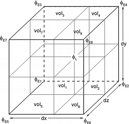
Flow velocities from the Eulerian approach are evaluated at the face of the staggered grids. However, for evaluating the forces acting on the particles, the fluid velocities at the particle centroids must be evaluated by certain interpolation techniques. Here, a volume averaged interpolation scheme for Eulerian-to-Lagrangian grid-mapping is used, i.e.,
5. SIMULATION OF SUB-GRID-SCALE (SGS) TURBULENT VELOCITY FLUCTUATIONS
To capture the full interaction of particles with the entire scales of local turbulence fluctuation, the effect of SGS eddies must be taken into account. The SGS turbulence fluctuations are random functions of space and time. The Monte Carlo velocity simulation techniques have been used as an economical method for generating time histories that have the random characters and statistical properties of turbulence. CitationKraichnan (1970) suggested a simple method for generating a Gaussian random field which resembles a pseudo-isotropic turbulence. Accordingly, the nondimensional Gaussian fluctuating random field is given as
In Equation (Equation18), N is the number of terms in the series, and the dimensionless quantities are defined as
In this study, the fluctuation velocity given by Equation (Equation18) is modified in order to make it suitable for generating the instantaneous SGS fluctuation velocities (u′ SGS i ). Here the average mesh size Δ c = (Δ x 1 × Δ x 2 × Δ x 3)1/3 is used for the length scale, l 0. It is also assumed that
It should be emphasized that the anisotropy of the SGS beyond the inertial subrange is important. In the present approach, parameter F2 as given by Equation (Equation7) (CitationMétais and Lesieur 1992; CitationDavid 1993; CitationSilveira et al. 1993) includes the mesh size, and therefore, the proposed modeling of the SGS fluctuation depends on the filter size that normally goes beyond the inertial subrange. While the original Kraichnan model used here is isotropic, the anisotropy of the SGS is taken into account with the use of the scaling parameters given by Equation (Equation24).
6. PARTICLE DEPOSITION VELOCITY
The dimensionless deposition velocity for particles released with a uniform concentration C 0 near a surface is defined as
N 0 is the initial number of particles uniformly distributed in a region within a distance of y 0 from the wall, and N d is the number of deposited particles in the time duration t d . In practice the time duration should be selected in the quasi-equilibrium (stationary) condition when Nd/t d + becomes constant.
A simple empirical equation for the nondimensional deposition velocity in duct flows was suggested by CitationWood (1981). That is,
CitationFan and Ahmadi (1993) developed an empirical equation for deposition of particles in vertical ducts including the effects of surface roughness and gravity along the flow direction, which is given as
Here, L 1 + = 3.08/(Sd +), g + = νu*3/g, and k+ is the surface roughness (which is set to zero for smooth surface in this study).
7. RESULTS
7.1. Instantaneous Fluid Velocity Field
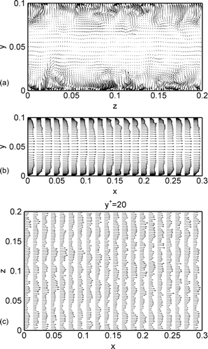
shows a sample instantaneous velocity field in different planes. While the velocity field in the yz-plane shown in has a random pattern, near-wall coherent eddies and flow streams towards and away from the wall can be clearly observed from this figure. The configuration of these eddies resembles those reported in earlier DNS simulations. shows the velocity vector plot in the xy-plane. The random deviations from the expected mean velocity profile are clearly seen. The velocity field in the xz-plane, aty + = 20 shown in indicates that the flow is predominantly in the x-direction. The low- and high-speed streaks are also noticeable in this figure.
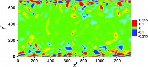
The temporal averaged iso-vorticity contours in the plane perpendicular to the flow direction are shown in . The temporal averaging was carried out for time duration of 50 wall units. The pattern of coherent counter rotating eddies near the wall can be clearly seen from this figure. The spacing of these eddies are of the order of 100 wall units.
The simulated root-mean-square (RMS) fluctuation velocities
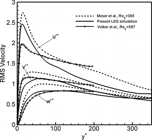
are shown in and are compared with the earlier high-resolution direct numerical simulation of CitationMoser et al. (1999) and the LES simulations of CitationVolker et al. (2002). While the general agreement is reasonable, it is seen that LES simulations results are somewhat lower than the DNS results. This is in part due to filtering of the smaller scales.
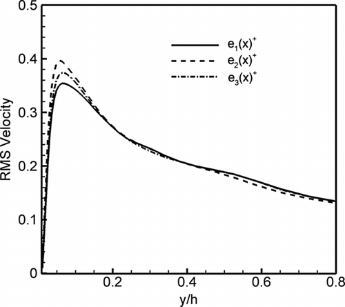
shows simulated non-dimensional root-mean-square (RMS) subgrid scale (SGS) fluctuation velocities,
Comparison of with shows that the SGS velocity fluctuations in x-direction are less than 12% of the corresponding total turbulence fluctuations while for y-direction it is more than 50% and for z-direction is about 35%. This observation shows that the current LES calculation has been able to capture the most of the turbulence fluctuations in streamwise direction but in the other two directions contribution of SGS fluctuations is large. It should be emphasized that the SGS fluctuations will vary depending on the size of the LES filter/grid size, and the correct evaluation of the SGS turbulence fluctuations in the direction normal to the wall have a profound effect on the deposition rate of particles.
Sample time variations of large eddy resolved velocity, SGS velocity fluctuations and the total velocity at a location of 35 wall units from the lower wall are shown in . All velocities are stated in wall units. The contributions of SGS fluctuations to components of turbulent velocity field can be seen in this figure.
FIG. 6 Sample time variations of filtered velocity, SGS fluctuation velocity, and simulated instantaneous velocity components at y + = 35.
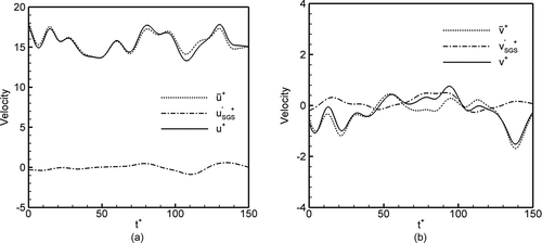
Considering the effect of SGS turbulent fluctuations on particle trajectory and the deposition rate analyses appears to be very important. This is particularly the case because of large contribution of SGS fluctuations in the direction normal to the wall.
7.2. Particle Mean Velocity and Velocity Fluctuations
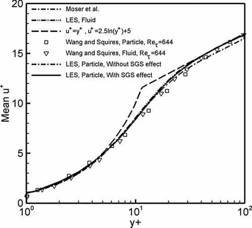
The first set of particle simulation is done by tracking and recording the velocity statistics of the 500,000 particles with the same relaxation time as those used in the LES work of CitationWang and Squires (1996) and DNS study of CitationRouson and Eaton (1994) in the presence or absence of SGS effect. (These correspond to their results for 28 μ m diameter Lycopodium particle.) Particles were initially distributed randomly with a uniform distribution in the entire channel. compares the predicted mean streamwise fluid and particle velocities with the simulation results of CitationMoser et al. (1999), CitationWang and Squires (1996), and the theoretical linear and logarithmic variations. It is observed that the LES simulated mean velocity profile of fluid is in good agreement with classical solutions and the DNS results. As expected, the Lycopodium particles follow the fluid flow and the mean particle velocity profile is in good agreement with the mean fluid velocity. In addition, the present LES simulation for the particle velocity is in good agreement with the simulation data of CitationWang and Squires (1996). also shows that the SGS fluctuations have no noticeable effect on mean streamwise velocity profile.
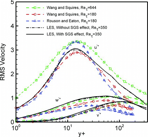
The simulated RMS particle velocity fluctuations are shown in and are compared with the results of CitationWang and Squires (1996) and DNS study of CitationRouson and Eaton (1994). Despite the variation in the flow Reynolds number, reasonable agreement in the trend of variation can be seen from his figure. also shows that the effect of SGS on particle RMS velocities is noticeable. In particular, the SGS increases the v′ component near the wall where its intensity is highest. The effect of SGS for the streamwise velocity fluctuation is much less.
7.3. Effect of SGS on particle deposition
Simulation results concerning the effect of subgrid scale velocity fluctuations on wall deposition of particles in turbulent channel flow are presented in this section. Several simulations for particle diameters between 1 to 130 μ m, with particle-to-air density ratio S = 2000, with and without SGS turbulent velocity fluctuations were performed. The diameters used and the corresponding nondimensional relaxation times, τ+ = τ u* 2 /ν, are listed in .
TABLE 1 Particle diameters and corresponding nondimensional relaxation times used in the simulation
The presence and absence of gravity force in streamwise direction was also studied. Ensembles of 50,000 particles were initially uniformly distributed within the distance of 1 to 30 wall units from the lower wall and their trajectories were analyzed for duration of 200 wall units. Initial particle velocities were set equal to the local fluid velocity. When the center of a particle reaches to a distance equal to its radius from the wall, the particle is considered to be deposited on the wall and the effect of rebound is neglected. The corresponding particle deposition velocities were evaluated and the results are presented in graphical form.
In the absence of gravity, variation of the simulated nondimensional deposition velocity with and without subgrid scale fluctuations versus nondimensional particle relaxation time are shown in . The experimental data collected by CitationPapavergos and Hedley (1984); and simulation results of CitationMcLaughlin (1989), Li and Ahmadi (1993), CitationHe and Ahmadi (1999), and CitationZhang and Ahmadi (2000); and the predictions of the empirical equations suggested by CitationWood (1981) and CitationFan and Ahmadi (1993) are shown in this figure for comparison. It is seen that the particle deposition velocity predicted by the LES including the subgrid scale fluctuations are in good agreement with the earlier DNS simulation results of CitationMcLaughlin (1989) and CitationZhang and Ahmadi (2000), experimental data and empirical model predictions. The effect of subgrid scale velocity fluctuations on the deposition rate of larger particle is relatively small. shows that for particles with relaxation time larger than 2 (diameters larger than 20 μ m) the LES simulations without the SGS fluctuation effect are in reasonable agreement with the earlier simulation and experimental data. However, when the SGS fluctuations are ignored, the LES simulation leads to no deposition for particles with diameters between 1 μ m to 11 μm. (Note that in these size ranges the effect of Brownian motion is quite small.) also shows that the deposition velocity markedly increases for d = 20 μ m by the effect of SGS fluctuations. While the SGS fluctuation always increases the deposition rate, its effect diminishes for particles larger than 30 μ m. Therefore, it is concluded that the effect of SGS fluctuations is quite important for proper predictions of deposition rate of small particles in the range of 1 μ m to 20 μ m.
FIG. 9 Variation of deposition velocity with particle relaxation time in the presence and absence of SGS effect.
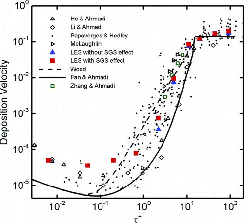
The slight differences of the LES simulations including the SGS fluctuation with the DNS simulation are in part due to the difference in Reynolds number of the flows studied. The DNS was for a Reynolds number of 8,000, while the LES simulation was performed for Re = 24,000. In addition, there are some statistical errors for certain size range due to the limitation on the number particles that are deposited.
shows the effect of gravity force in the streamwise direction on the particle deposition velocity. Here the effects of SGS fluctuations are included in the LES simulations, and particles larger than 11 μ m (nondimensional relaxation time of 2) were studies. This figure shows that the effect of gravity on 11 μ m particles is small. For larger particles, however, the presence of streamwise gravity increases the deposition velocity. According to CitationFan and Ahmadi (1993), when gravity is in the flow direction, the shear-induced lift force is toward the wall (since the heavy particles move faster than the fluid); thus, the deposition rate increases. This figure shows that the present simulation results are in good agreement with the DNS data of CitationZhang and Ahmadi (2000) for both cases with presence and absence of gravity.
FIG. 10 Variation of deposition velocity with particle relaxation time in the presence and absence of gravity force.
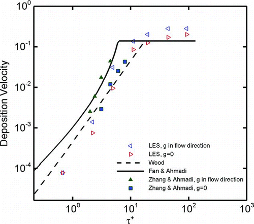
Careful examination of the simulation results shows that for particles less than 45 microns, the particle Reynolds number is less than 1, and Re becomes much smaller than 1 for smaller particles. For particles larger than 45 μ m, however, Re could become larger than 1 for certain period of time. Under such conditions, the accuracy of the Saffman equation becomes questionable, and the effect of gravity-induced deposition could deviate from the predictions shown in .
7.4. Deposition Pattern
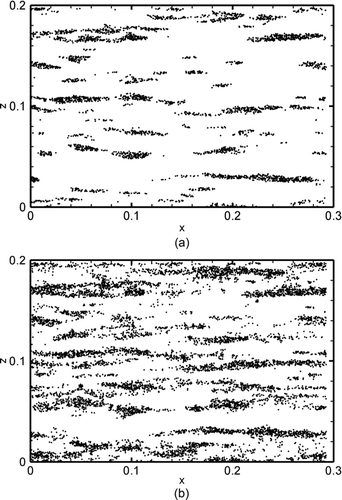
To study the effect of near wall coherent eddies on the pattern of particle deposition, a series of simulations were performed with 45 μ m particles being initially distributed uniformly in a region within 30 wall units from the lower wall. These particles were tracked and particles that are deposited are identified. The distributions of the initial xz locations of the deposited particles were recorded and their distribution patterns are discussed in this section. The cases that SGS scale fluctuations are included and ignored are compared and discussed.
shows the distribution of the initial locations of deposited particles in xz plane in time duration of 50 wall units in the presence and absence of SGS fluctuations. It is observed that the initial locations of deposited particles are concentrated in certain bands. The SGS fluctuations increase the number of deposited particles but do not alter the pattern of the initial location of deposited particles significantly. This implies that the near the wall coherent eddies play a critical role in particle deposition. According to CitationOunis et al. (1993) these bands corresponds to the down flowing region of near wall counter rotating eddies. CitationOunis et al. (1993) observed this trend using their DNS at much lower Reynolds number. The present results show that this trend continues at higher Reynolds number and the present LES method is capable of capturing this effect. The effect of presence of gravity in the streamwise direction on the deposition pattern of the particle was also studied, but there is no noticeable change in the initial location of the deposited particle. Therefore, the corresponding figures are not shown here to save space.
8. Conclusions
In this work a model for including the effect of subgrid scale fluctuations on the particle tracking in the LES was developed. The LES of a turbulent channel flow was performed using the Selective Structured Function model. The drag, lift, Brownian, and gravity forces were included in the particle equation of motion. The Brownian force was simulated as a white noise process. The deposition process of near wall particles was simulated using the Lagrangian tracking approach.
SGS velocity fluctuations are simulated by the Kriachnan's Gaussian random field scaled with the appropriate SGS intensities. These modeled fluctuations are added to filtered resolved velocities evaluated by the LES and used in particle equation of motion.
For different particle sizes, effects of the SGS fluctuations on particle deposition velocity were studied, and the effect of presence of gravity was examined. Based on presented results, the following conclusions are drawn:
-
The LES with the “Selective Structured Function model” is capable of simulating the near wall coherent eddy structures in turbulent channel flows.
-
The contribution of the SGS intensities in the streamwise direction is relatively small. However, in the spanwise and normal directions, the SGS contribution to the fluctuation velocity reaches to about 50%. The SGS fluctuation in normal direction has an important effect on the particle deposition in certain size range.
-
When SGS fluctuations are included in the model, the simulated deposition velocities for particles in the size range of 1 μ m (τ+ = 0.0064) to 11 μ m(τ+ = 0.67) are in good agreement with available experimental data. When the SGS fluctuation is ignored, the model leads to erroneous results of zero deposition for this size range.
-
For 20 μ m (τ+ = 2.2) particles the SGS fluctuations increase the particle deposition rate. For 30 μ mparticles or larger, the effect of subgrid scale fluctuations is relatively small.
-
Gravity force in the streamwise direction increases the deposition velocity for heavy particles.
-
Initial locations of deposited particles are concentrated in bands along the flow; these patterns may be attributed to the formation of near wall coherent turbulence eddies.
The work of MS and GA was supported by grants from the National Science Foundation and Environmental Protection Agency.
REFERENCES
- Ahmadi , G. 1993 . “ Overview of Digital Simulation Procedures for Aerosol Transport in Turbulent Flows ” . In Particle in Gases and Liquids 3: Detection, Characterization, and Control , Edited by: Mittal , K. L. 1 New York : Plenum .
- Armenio , V. , Piomelli , U. and Fiorotto , V. 1999 . Effect of the Subgrid Scales on Particle Motion . Phys. Fluids. , 11 : 3030
- Brooke , J. W. , Kontomaris , K. , Hanratty , T. J. and McLaughlin , J. B. 1992 . Turbulent Deposition and Trapping of Aerosols at a Wall . Phys. Fluids. , A4 : 825 – 834 .
- Champagne , F. H. , Friehe , C. A. , LaRue , J. C. and Wyngaard , J. C. 1977 . Flux Measurements, Flux Estimation Techniques and Fine-Scale Turbulence Measurements in the Unstable Surface Layer Over Land . J. Atmos. Sci. , 34 : 515 – 30 .
- Cleaver , J. W. and Yates , B. 1975 . A Sublayer Model for Deposition of the Particles from Turbulent Flow . Chem. Eng. Sci. , 30 : 983 – 992 .
- David , E . 1993 . Modilisation des icoulements compressibles et hypersoniques: une approche instationnaire , PhD thesis Grenoble : Natl. Polytech. Inst. .
- Fan , F.-G. and Ahmadi , G. 1993 . A Model for Turbulent Deposition of Particles in Vertical Ducts with Smooth and Rough Surfaces . J. Aerosol Sci. , 24 : 45 – 64 .
- He , C. and Ahmadi , G. 1999 . Particle Deposition in a Nearly Developed Turbulent Duct Flow with Electrophoresis . J. Aerosol Sci. , 30 : 739 – 758 .
- Hinds , W. C. 1982 . Aerosol Technology , New York : Academic Press .
- Hinze , J. O. 1975 . Turbulence , New York : McGraw-Hill .
- Kraichnan , R. H. 1970 . Diffusion by Random Velocity Field . Phys. Fluids. , 11 : 43 – 62 .
- Kuerten , J. G. M. 2006 . Subgrid Modeling in Particle-Laden Channel Flow . Phys. Fluids. , 18 025108
- Lesieur , M. and Métais , O. 1996 . New Trends in LES of Turbulence . Ann. Rev. of Fluid Mech. , 28 : 45 – 82 .
- Li , A. and Ahmadi , G. 1993a . Computer Simulation of Deposition of Aerosols in a Turbulent Channel Flow with Rough Wall . Aerosol Sci. Technol. , 18 : 11 – 24 .
- Li , A. and Ahmadi , G. 1993b . Deposition of Aerosols on Surfaces in a Turbulent Channel Flow . Int. J. Eng. Sci. , 31 : 435 – 451 .
- McLaughlin , J. B. 1989 . Aerosol Particle Deposition in Numerically Simulated Turbulent Channel Flow . Phys. Fluids. , A1 : 1211 – 1224 .
- Métais , O. and Lesieur , M. 1992 . Spectral Large Eddy Simulations of Isotropic and Stably-Stratified Turbulence . J. Fluid Mech. , 239 : 157 – 194 .
- Moinat , P. and Djilali , N. 2001 . Application of Large-Eddy-Simulation to High-Reynolds Number Separated Flow . Comput. Fluid Dynamics. , 10 : 116 – 131 .
- Moser , R. D. , Kim , J. and Mansour , N. N. 1999 . Direct Numerical Simulation of Turbulent Channel Flow up to Re τ = 590 . Phys. Fluids , 11 : 943 – 945 .
- Ounis , H. , Ahmadi , G. and McLaughlin , J. B. 1991 . Dispersion and Deposition of Brownian Particles from Point Sources in a Simulated Turbulent Channel Flow . J. Colloid Interface Sci. , 147 : 233 – 250 .
- Ounis , H. , Ahmadi , G. and McLaughlin , J. B. 1993 . Brownian Particle Deposition a Directly Simulated Turbulent Channel Flow . Phys. Fluids. , A5 : 1427 – 1432 .
- Papavergos , P. G. and Hedley , A. B. 1984 . Particle Deposition Behavior from Turbulent Flows . Chem. Engng Res. Des , 62 : 275 – 295 .
- Pendinotti , S. , Mariotti , G. and Banerjee , S. 1992 . Direct Numerical Simulation of Particle Behavior in the Wall Region of Turbulent Flows in Horizontal Channels . Intl. J. Multiphase Flow. , 18 : 927 – 941 .
- Rouson , D. W. I. and Eaton , J. K. Direct Numerical Simulation of Particles Interacting with a Turbulent Channel Flow . Proceedings of the 7th Workshop on Two-Phase Flow Predictions . Erlangen, Germany. Edited by: Sommerfeld , M.
- Shotorban , B. and Mashayek , F. 2005 . Modeling Subgrid-Scale Effects on Particles by Approximate Deconvolution . Phys. Fluids. , 17 081701
- Silveira , N. A. , Grand , D. , Metais , O. and Lesieur , M. 1993 . A Numerical Investigation of the Coherent Structures of Turbulence Behind a Backward-Facing Step . J. Fluid Mech. , 256 : 1 – 25 .
- Suksangpanomrung , A. 1999 . Investigation of Unsteady Separated Flow and Heat Transfer Using Direct and Large-Eddy Simulations , PhD Thesis Victoria, Canada : Department of Mech. Eng. University of Victoria .
- Uijttewaal , W. S. J. and Oliemans , R. V. A. 1996 . Particle Dispersion and Deposition in Direct Numerical and Large Eddy Simulation of Vertical Pipe Flows . Phys. Fluids , 8 : 2590
- Vance , M. W. , Squires , K. D. and Simonin , O. 2006 . Properties of the Particle Velocity Field in Gas-Solid Turbulent Channel Flow . Phys. Fluids. , 18 063302
- Volker , S. , Moser , R. D. and Venugopal , P. 2002 . Optimal Large Eddy Simulation of Turbulent Channel Flow Based on Direct Numerical Simulation Statistical Data . Phys. Fluids , 14 : 3675
- Wang , Q. and Squires , K. D. 1996 . Large Eddy Simulation of Particle Deposition in a Vertical Turbulent Channel Flow . Int. J. Multiphase Flow. , 22 : 667 – 683 .
- Wang , Q. and Squires , K. D. 1996 . Large Eddy Simulation of Particle-Laden Turbulent Channel Flow . Phys. Fluids. , 8 : 1207 – 1223 .
- Wood , N. B. 1981 . A Simple Method for Calculation of Turbulent Deposition to Smooth and Rough Surfaces . J. Aerosol Sci. , 12 : 275 – 290 .
- Yeh , F. and Lei , U. 1991 . On the Motion of Small Particles in a Homogeneous Isotropic Turbulent Flow . Phys. Fluids , A3 : 2571 – 2586 .
- Zhang , H. and Ahmadi , G. 2000 . and Horizontal Turbulent Duct Flows . J. Fluid Mech. , 406 : 55 – 80 .
