Abstract
Most filtration models assume that the air stream runs perpendicularly to the orientation of the filter fibers. However, cigarette filters remove aerosol particles apparently by a different filter configuration in that the fiber orientation almost parallels the air streamlines. To focus on the effect of fiber orientation, cellulose acetate filters were used in this work to facilitate the filter performance comparison. A piece of original round cigarette filter was molded to form a cube. The same piece of filter was used for both perpendicular and parallel orientations, to avoid the variability caused by the non-uniform filter media distribution. DOP aerosol particles used in the tests were generated by either a constant output aerosol nebulizer or an ultrasonic atomizing nozzle. A Po-210 radiation source was used to neutralize the challenge aerosols to the Boltzmann charge equilibrium. A scanning mobility particle sizer (for < 0.8 μm) and an aerodynamic particle sizer (for > 0.8 μm) were used to measure aerosol number concentrations and size distributions upstream and downstream of the cigarette filters. The results showed that parallel and orthogonal filters behave similarly. However, the pressure drop across parallel filter was lower than for the perpendicular filter, indicating that the airflow is more laminar passing through the parallel filters. Possibly for the same reason, aerosol penetration through parallel filter was higher than the orthogonal filter, although the difference may not be statistically significant. When a comparison of the fiber orientation is based on filter quality, orthogonal filter performs better than parallel filter, if face velocity is lower than 60 cm/s. Parallel filter performs better only when the particles are smaller than the most penetrating size and under high face velocity.
INTRODUCTION
Many aerosol scientists have contributed to the development of modern filtration theories. There are a number of excellent reviews that summarize, compare, and correlate derived theoretical or empirical models with experimental data (CitationYeh and Liu 1974a,b; Nguyen and Beeckmans 1975; Ingham 1981; Brown 1984 1989; Liu and Rubow 1986; Zhang and Liu 1992; Walsh and Stenhouse 1997; Barrett 1998; Romay et al. 1998). As a result, filter performance can now be predicted with acceptable accuracy. Nevertheless, most of the previous experimental and/or theoretical studies have considered only orthogonal filters, i.e., the direction of airflow is perpendicular to the fiber orientation. An early theoretical work on diffusional single fiber efficiency of nearly parallel flow indicated that diffusion deposition on fibers parallel to the mean direction of flow is significant when compared to deposition rates for transverse flows (CitationBanks and Kurowski 1988). However, experimental studies of the parallel filters are very limited. Therefore, it is interesting and may be important in some applications, to compare the filtration characteristics of these two filter types, from the standpoint of filter quality factor.
Cigarette filters have been designed to reduce the cigarette tar yields. In addition to its aesthetic and healthy values, a filter reduces the cost of the cigarette because it is cheaper than the tobacco. Filter rod making begins when a highly compacted form of cellulose acetate filter tow arrives at a rod-making operation. For the filter material to be most effective, the fibers must have the maximum amount of their surfaces exposed to the smoke stream. Consequently, the initial operation in rod making must be the separation of the individual fibers from one another. The main physical characteristics of the cigarette filter rod are defined in terms of length, circumference, firmness or compressibility, weight and pressure drop, or resistance to draw. The packing density (or weight) is an important factor in determining firmness, pressure drop, and cost of production. The amount of fiber in the rod determines its density and, in turn, its firmness or resistance to compression. The bonding agent in the rod forms welds the fibers and also serves to add rigidity to the fiber mass. Within the usual limits, firmness increases with increasing bonding. Individual fiber denier and cross-section also influence firmness. The cigarette filter is one of the few parallel filters readily available on the market, and was selected as the test filter in this work.
Single Fiber Theory
Single fiber theories are normally used to calculate the total filtration efficiency (CitationHinds 1999). Aerosol penetration P n for a particle with n elementary charges is given by:
The single fiber efficiency due to diffusional deposition is given by (CitationLee and Liu 1982):
The density of the particle is represented by ρ p , and C c , is the Cunningham slip correction factor. Viscosity of air is η and J is:
In addition to Yeh and Liu's semi-empirical equation concerning impaction, CitationNguyen and Beeckmans (1975) proposed the following equation to estimate the single fiber impaction efficiency:
and K 1 = 4, K 2 = 2250, K 3 = 4, and K 4 = 65 for real filters.
This equation has the advantage that it will not exceed unity, given that the constants K 1 to K 4 are positive.
Nguyen and Beeckmans' equation actually was a modification of the equation proposed by CitationLandahl and Herrmann (1949):
The single fiber filtration efficiency caused by aerosol gravitational settling is given by (CitationYeh and Liu 1974a,b):
It is assumed that the particle charges are in Boltzmann charge equilibrium. The interaction terms between the individual mechanisms are not within the scope of the present study. The spreadsheet (Microsoft Excel) used in previous studies (CitationChen and Huang 1998; CitationHuang et al. 2007) was employed to calculate and integrate the filtration efficiency by each individual filtration mechanism.
Collection efficiency alone is not enough to distinguish good filters from bad filters, because pressure drop across the filter is an equally important factor that needs to be considered when ranking the quality of filters. The filter quality factor, q f , is normally used as an indicator of the filter media performance (CitationHinds 1999),
The pressure drop represents the total drag force of all the fibers in a filter. In the Stokes flow regime, the pressure drop varies linearly with the face velocity. Brown (1983) gives the pressure drop as:
The function f(α) varies among theories, and there is no simple expression equation for a fiber of square cross section (Brown 1983).
EXPERIMENTAL MATERIALS AND METHODS
Cellulose acetate tow filters acquired from a local tobacco company were used in this work. The basic properties of this filter are listed in .
TABLE 1 Properties of tested filter
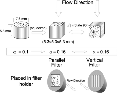
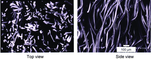
This filter rod constitutes 25 mm of length and 7.6 mm of diameter, with packing density of about 0.1 and equivalent fiber size of 18 μ m (a denier per filament of 3). In order to investigate the effects of fiber orientation on filtration characteristics by using the same filter disc and filter holder, a filter cubic was prepared. The filter was first cut into several shorter rods of 5.3 mm in length, which is an arbitrary value smaller than rod diameter. This rod was then manually shaped and compressed to form a cube with the dimension of 5.3 mm, as shown in . The compaction increased the packing density from 0.1 to 0.16, and helped to fix the filter cube in the filter holder. In the present study, when aerosols flow into the conventional cigarette filter rod, i.e., the flow direction parallels the fibers' longitudinal direction, the filter is designated a parallel filter. By rotating this cube 90 degrees, the filter becomes an orthogonal filter, the more conventional filter media orientation, in which air flows perpendicular to the fiber orientation. The same piece of filter cube was used for both parallel and perpendicular directions, to eliminate the variability of cigarette filters. Micrographs in showed parts of cross sections of the filter cubes in the two directions. Notice that the fibers were not perfectly straight, and this could be one of the research limitations of this study.
FIG. 2 SEM photos of cigarette filter showing fibers in two directions. (Figure provided in color online.)
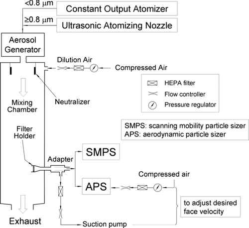
To conduct the aerosol penetration test, aerosol particles with different size distributions were generated by the two aerosol generation systems, as shown in . Dioctylphthalate (DOP) was chosen as the test agent. A constant output atomizer (model 3076, TSI Inc., St. Paul, MN) and an ultrasonic atomizing nozzle (model 8700-120, Sonotek Inc., Highland, NY) were used to generate polydisperse submicrometer-sized and micrometer-sized aerosol particles, respectively. In order to avoid a particle charge effect, the particles were then passed through a 22.5-mCi Po-210 radioactive source (model P-2001, NRD Inc.) to neutralize the aerosol particles to the Boltzmann charge equilibrium. An aerosol electrometer (model 3068, TSI, Inc.) was used downstream of the test chamber to monitor the aerosol charge neutralization. Two different spectrometers measured the aerosol concentration and size distribution: a scanning mobility particle sizer (SMPS, model 3934U, TSI Inc.) for particles smaller than 0.8 μ m, and an aerodynamic particle sizer (APS, model 3321A, TSI Inc.) for particles larger than 0.8 μ m. Although SMPS and APS size particles by different principles, the data combination has been shown feasible after proper calibration and operation (CitationKuo et al. 2005).
Five filter rods were used for aerosol penetration and air resistance measurements. Two of the five filter cubes were tested under parallel direction first, while others began with perpendicular direction. The default sampling flow rates of SMPS and APS were 0.3 and 5.0 L/min, respectively. The corresponding face velocities through the tested cigarette filter cube were 18 and 300 cm/s, respectively. As showed in , an external suction pump and a make-up air system were equipped with SMPS and APS, respectively. This allowed adjustments for desired face velocity. Seven face velocities ranging from 18 to 300 cm/s were applied to study flow dependency. All flows were controlled and monitored by mass flow controllers (Hastings Instrument, Hampton, VA), which were calibrated using an electronic bubble meter (Gilibrator, Gilian Instrument Corp., Wayne, NJ). For data analysis, the experimental data were imported to a curve-fitting package (TableCurve 2D Windows v4.07, Copyright 1989–1996 AISN Software Inc., Florence, OR) to find the best fitting straight line through a set of data points.
RESULTS AND DISCUSSION
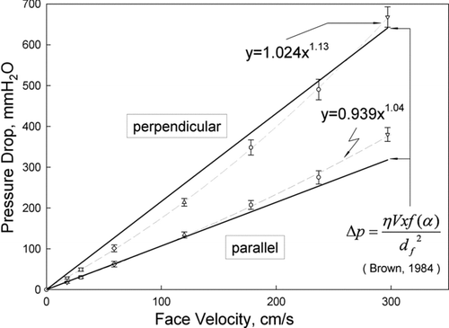
The pressure drop across the orthogonal filters was significantly higher than that across parallel filters, as shown in . Airflow through parallel filters is similar to flow through numerous pipes and tends to be laminar for Reynolds number less than 2000. As aforementioned, laminar flow in a filter is expected when the pressure drop is directly proportional to the face velocity. When the data start to deviate from linearity, it indicates a transition of flow possibly from the laminar region to the turbulent region. Therefore, the exponent of the power fit curve of parallel filter (1.04) was only slightly higher than 1, indicating that airflow must be quite laminar when passing the channels formed by the parallel fibers. On the other hand, airflow through orthogonal filters is speculated to produce eddies downstream of fibers since the exponent of the power fit curve was 1.13. The turbulent level increases with increasing air flow rate. Moreover, the pressure drop patterns of both the vertical and parallel filters agree reasonably well with the semi-empirical model developed by CitationBrown (1984). Any mismatch with the Brown's model possibly is due to inhomogeniety of the filter rods, a bias in estimating fiber diameter, and a less symmetrical shape of the fiber.
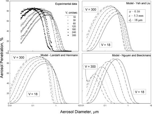
Aerosol penetration curves of perpendicular and parallel filters appeared similar, as shown in . No significant aerosol loading effect was observed apparently due to high aerosol penetration and short sampling time. The most penetrating size (MPS), also referred to as collection minimum, decreased with increasing face velocity. The MPS was about 0.5 μ m when face velocity was set at 18 cm/sec, and the MPS may become less than 0.1 μ m if the face velocity goes beyond 300 cm/sec. It is worthwhile to note that the whole penetration curve moved toward the smaller aerosol size. For particles smaller than MPS, the aerosol penetration increased with increasing face velocity, apparently due to shorter retention time for aerosol deposition by diffusion. For particles larger than MPS, the aerosol penetration decreased with increasing face velocity because, of higher inertial force.
FIG. 5 Aerosol penetration through perpendicular and parallel filters under different face velocities, showing as a function of aerosol size.
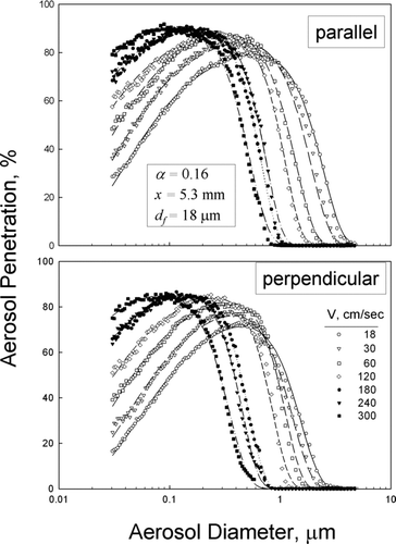
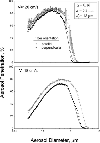
From , it is difficult to make a distinction as to which type of filter has better collection efficiency or lower aerosol penetration. In order to better demonstrate the difference in filter performance and the effect of face velocity, only two extreme velocity cases (18 and 120 cm/s) were shown in . In , the large error bars of aerosol penetration in the micrometer-sized range were due to the low challenge aerosol concentration generated by ultrasonic atomizer. Only one curve was shown with error bar for legible reason. If both aerosol penetration curves were plotted with error bar, there would be an obvious overlapping zone, indicating that the difference between these two cases may not be “statistically significant.” Yet, without error bar overlapping, clearly shows that aerosol penetration through parallel filters is higher than that through orthogonal filter, very likely for the same reason that parallel filters created lower air resistance, at the cost of higher aerosol penetration. The differences in aerosol penetration appeared to shrink as the face velocity increased, possibly because the airflow became more turbulent which resulted in higher aerosol deposition. Our aerosol penetration data showed the same trend with Banks and Kurowski's theoretical work, which indicated that deposition resulting from the parallel components of flow is not negligible. For example, the value of collection efficiency at the most penetrating size of around 0.3 μ m for parallel filter is about 65% of the those perpendicular filter, when the filtration velocity is 18 cm/s. For particle size away from the most penetrating size, whether it is larger or smaller, the ratio increases. However, direct comparison is difficult because of different domains of filter packing density and velocity.
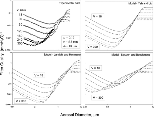
When the experimental data were compared with the models, the early equation of Landahl and Herrmann had the best agreement (shown in ), in particular on the right side of the MPS. It was apparently over-modified by Nguyen and Beeckmans because the aerosol penetration and the most penetrating sizes are lower and/or smaller than the experiments. The equation by Yeh and Liu appeared to perform reasonably well on the size range smaller than the MPS.
shows the filter quality of the tested orthogonal filters. Filter quality increased with decreasing face velocity for submicrometer-sized particles because diffusion was more important than other filtration mechanisms. Superior performance under low filtration velocity indicated that filter with larger surface area should be utilized in order to have lower face velocity and therefore improve the filter quality, if submicrometer-sized aerosols are of concern. As the particle size increased, the filter quality increased with increasing face velocity because inertial impaction was the dominating filtration mechanism. The modeled filter quality by early Landahl and Hermmann again had the closest match with the experimental data. The transition between 1 to 2 μ m is unique. No good explanation for this transition phenomenon is available at this time.
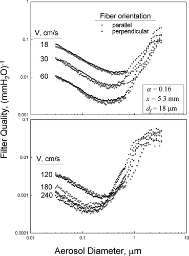
The pressure drop across orthogonal filters was almost twice that of the parallel filters as shown in . Yet the turbulence and energy dissipation downstream of the fibers enhanced the collection efficiency, and the consequential filter quality factors were almost identical, as shown in . However, for filters operated under lower face velocity (< 60 cm/s), the orthogonal filters performed slightly better than the parallel filters when examined closely over the whole size range. For particles with diameter less than the MPS, the parallel filter should be used for its higher filter quality factor when the face velocity was higher than 120 cm/s, as shown in the lower plot of .
CONCLUSIONS AND RECOMMENDATIONS
Air resistance triggered by orthogonal filters is about two times higher than that by parallel filters because of the turbulence occurring downstream of orthogonal fibers. However, the extra energy needed to overcome the pressure drop across the orthogonal filters did not simply dissipate. In fact, the orthogonal filter almost totally regained the dissipated energy and converted it to higher collection efficiency. Therefore, the filter qualities of vertical and parallel filters are about the same despite the huge difference in air resistance.
In general, orthogonal filters perform better than parallel filter over all size ranges. The parallel filter might perform better only when particles are smaller than the most penetrating size and under high face velocity, from the perspective of filter quality.
The authors would like to thank the National Science Council (Grant No. NSC90-2320-B-002-191) for the financial support.
REFERENCES
- Banks , D. O. and Kurowski , G. J. 1988 . Diffusion Deposition on a Cylinder Due to Nearly Parallel Flow . Aerosol Sci. Technol. , 8 : 189 – 196 .
- Barrett , L. W. 1998 . Aerosol Loading Performance of Electret Filter Media . Am. Ind. Hyg. Assoc. J. , 59 ( 8 ) : 532 – 539 .
- Brown , R. C. 1984 . A Many-Fibre Model of Airflow Through a Fibrous Filter . J. Aerosol Sci. , 15 ( 5 ) : 583 – 593 .
- Brown , R. C. 1989 . Modern Concepts of Air Filtration Applied to Dust Respirators . Ann. Occup. Hyg. , 33 : 615 – 644 .
- Chen , C. C. , Lehtimaki , M. and Willeke , K. 1993 . Loading and Filtration Characteristics of Filtering Facepieces . Am. Ind. Hyg. Assoc. J. , 54 ( 2 ) : 51 – 60 .
- Chen , C. C. and Huang , S. H. 1998 . The Effect of Particle Charge on the Performance of an Electret Filtering Facepiece . Am. Ind. Hyg. Assoc. J. , 59 ( 4 ) : 227 – 233 .
- Hinds , W. C. 1999 . Aerosol Technology, , Second Edition , 182 – 202 . New York : John Wiley and Sons, Inc. .
- Huang , S. H. , Chen , C. W. , Chang , C. P. , Lai , C. Y. and Chen , C. C. 2007 . Penetration of 4. 5 nm to 10 μ m Aerosol Particles through Fibrous Filters . J. Aerosol Sci. , 38 ( 7 ) : 719 – 727 .
- Ingham , D. B. 1981 . The Diffusional Deposition of Aerosols in Fibrous Filter . J. Aerosol Sci. , 12 : 357 – 365 .
- Kuo , Y. M. , Huang , S. H. , Shih , T. S. , Chen , C. C. , Weng , Y. M. and Lin , W. Y. 2005 . Development of a Size-Selective Inlet Simulating ICRP Lung Deposition Fraction . Aerosol Sci. Technol. , 39 ( 5 ) : 437 – 443 .
- Landahl , H. and Hermann , K. J. 1949 . Sampling of Liquid Aerosols by Wires, Cylinders and Slides, and the Efficiency of Impaction of Droplets . J. Colloid Sci. , 4 : 103 – 136 .
- Lee , K. W. and Liu , B. Y. H. 1982 . Theoretical Study of Aerosol Filtration by Fibrous Filter . Aerosol Sci. Technol. , 1 : 147 – 161 .
- Lee , K. W. and Ramamurthi , M. 1993 . “Filter Collection,” . In Aerosol Measurement: Principles, Techniques, and Applications , Edited by: Willeke , K. and Baron , P. A. New York : Van Nostrand Reinhold .
- Liu , B. Y. H. and Rubow , K. L. 1986 . “ Air Filtration by Fibrous Media ” . In Fluid Filtration: Gas , ASTM STP 975 Edited by: Raber , R. R. Volume 1 , 1 – 12 .
- Nguyen , X. and Beeckmans , J. M. 1975 . Single Fiber Capture Efficiencies of Aerosol Particles in Real and Model Filters in the Inertial–Interceptive Domain . J. Aerosol Sci. , 6 : 205 – 212 .
- Romay , F. J. , Liu , B. Y. H. and Chae , S. J. 1998 . Experimental Study of Electrostatic Capture Mechanisms in Commercial Electret Filters . Aerosol Sci. Technol. , 28 ( 3 ) : 224 – 234 .
- Walsh , D. C. and Stenhouse , J. I. T. 1997 . The Effect of Particle Size, Charge, and Composition on the Loading characteristics of an Electrically Active Fibrous Filters Material . J. Aerosol Sci. , 2 : 307 – 321 .
- Yeh , H. C. and Liu , B. Y. H. 1974a . Aerosol Filtration by Fibrous Filters—I. Theoretical . J. Aerosol Sci. , 5 : 191 – 204 .
- Yeh , H. C. and Liu , B. Y. H. 1974b . Aerosol Filtration by Fibrous Filters—II. Experimental . J. Aerosol Sci. , 5 : 205 – 217 .
- Zhang , Z. and Liu , B. Y. H. 1992 . Experimental Study of Aerosol Filtration in the Transition Flow Region . Aerosol Sci. Technol. , 16 : 227 – 235 .
