Abstract
Computational fluid dynamics (CFD) was used to study aerosol penetration through the entrance section of a bell-shaped omni-directional ambient aerosol sampling inlet. The entrance section did not include either an insect screen or a large-particle pre-separator. Simulations of the flow field were carried out for wind speeds of 2, 8, and 24 km/h and a fixed exhaust flow rate of 100 L/min; and, particle tracking was performed for 2 to 20 μ m aerodynamic diameter particles. Penetration calculated from CFD simulations was in excellent agreement with experimental results from previous studies with the root mean square relative error between simulation and experimental data being 3.8%. CFD results showed that the most significant regional particle deposition occurred on the upwind side of a curved flow passage between two concentric axisymmetric shells of the inlet housing and that deposition at the leading edges of the shells and within the exhaust tube was far less significant. At a wind speed of 2 km/h, penetration was affected by gravitational settling, e.g., penetration of 20 μ m particles was 71.9% when gravity was included and 80.4% without gravity. At higher wind speeds gravity had little effect. An empirical equation was developed to relate aerosol penetration to a Stokes number, a gravitational settling parameter, and a velocity ratio. Good fits of the correlation curves to experimental data and numerical results were obtained.
1. INTRODUCTION
Sampling inlets are used in ambient monitoring of environmental pollutants, perimeter monitoring of industrial and nuclear facilities, and global monitoring of radionuclides (CitationLiu and Pui 1981; CitationMcFarland et al. 1992; CitationMcKinnon et al. 1998; CitationPleil et al. 1993; CitationWitschger 2000). The sampling of airborne particles ideally involves obtaining an accurate representation of the concentration of a pre-selected range of the prevailing size distribution, with the sample characteristics independent of environmental conditions. To obtain accurate measurement results, a representative aerosol sample, encompassing the size range of interest, must be drawn through the inlet into the particle measuring or collecting device. As the first component of a sampling system, the performance of the inlet is critical. The ideal aerosol inlet would allow 100% penetration of the particles of interest; however, the samples can be biased by both the aspiration efficiency and by depositional losses on internal components (CitationMcMurry 1999).
Two types of inlets are used for aerosol monitoring, namely, uni-directional and omni-directional. Unidirectional inlets, such as shrouded probes (McFarland et al 1987; CitationChandra and McFarland 1997), are more applicable to higher speed sampling applications, e.g., wind speeds greater than about 24 km/h (15 miles/h), as typified by source and mobile-platform monitoring systems where the direction of the free stream is known (CitationBisgaard 1995). Omni-directional inlets, which are the focus of this study, are used extensively in ambient air sampling where the free stream velocity vector is highly variable and a properly designed inlet should be able to sample independent of wind speed and direction (CitationGao et al. 1999). The inlet should also prevent precipitation, debris and insects from affecting the quality of the sample.
Typically, an omni-directional inlet system for use in the ambient environment is comprised of three components, an entrance section, an insect screen and a pre-separator. The entrance section generally draws in a sample of the horizontally directed wind, and changes the flow direction to vertical while adjusting the velocity from a variable value associated with wind speed to a fixed value that corresponds to the sampling flow rate. The roles of the insect screen and pre-separator are to scalp large unwanted debris and particles from the aspirated size distributed. Only the entrance section is considered in this study, as the insect screen and pre-separator in an inlet system are additional components that are added to custom-fit the injested size distribution before its delivery to a collector or analyzer.
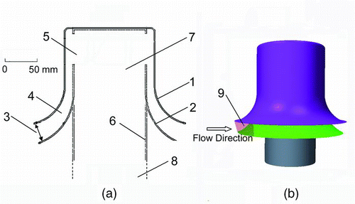
Omni-directional inlets typically have circumferential intakes that allow particles to be aspirated regardless of the wind direction (CitationLiu and Pui 1981). The Bell Shaped Inlet entrance section used in this study, which is referred to as BSI-e herein, is shown in . It is similar in design to an ambient aerosol sampling inlet developed by McFarland et al. (1977). In the BSI-e, aerosol enters the device through a circumferential intake, formed by a gap between two shells of the inlet housing, and then flows upward through the between-shell passage. The aerosol then makes a 180° turn while passing through windows and into a downward directed exhaust tube. The exhaust tube is closely fit within the inner shell. CitationWedding et al. (1980) used a variation of the BSI-e design in a PM-10 aerosol sampler, in which the inner shell was curved and outer shell was straight with no extended rim. Loss by inertial impaction on the inner shell was studied (CitationWedding et al. 1980). CitationNene (2006) and CitationBaehl (2007) tested the BSI-e in a wind tunnel and determined the effects of wind speed and particle size on aerosol penetration.
FIG. 1 (a) Cross-sectional view of the 100 L/min Bell-Shaped Inlet entrance section (BSI-e). In the figure: 1. Outer shell; 2. Inner shell; 3. Intake gap; 4. Between-shell passage; 5. Windows; 6. Exhaust tube; 7. Entrance of the exhaust tube; 8. Exit plane of exhaust tube; 9. Intake surface (facing the wind). (b) A 3- D view of the BSI-e.
Historically, the design of omni-directional aerosol inlets such as the BSI-e has been based on empiricism. Due to the complex flow fields, success in numerical modeling particle deposition mechanisms in an omni-directional aerosol inlet has been very limited; which in turn, has hindered the development of correlations between particle penetration and dimensionless numbers. As an example, CitationNene (2006) developed a semi-empirical correlation for the BSI-e inlet that was based on wind tunnel data, however that correlation showed large deviations for the low wind speed case (2 km/h).
Computational fluid dynamics (CFD) simulation has been used to aid in the design of some aerosol devices, and it has proven to be a useful tool. Gong et al. (1993, 1996) carried out numerical simulations of a shrouded probe aerosol inlet, which has flow that can be treated in a two-dimensional manner. CitationHu and McFarland (2007) used CFD simulation to gain valuable insight into the aerosol behavior and the location of particle deposition in a wetted wall bioaerosol sampling cyclone. CFD simulation has been applied in several previous aerosol inlet studies. CitationWeber and Wise (1997) developed a CFD model to simulate flow around an aerosol inlet in a wind tunnel, and assessed the effects of sampler-caused blockage on the flow field. CitationGao et al. (1999) calculated aerosol penetration through an omni-directional aerosol inlet, which was an inverted funnel, for wind speeds up to 1.4 m/s (5.0 km/h). The computed penetration agreed well with experimental results for large particle sizes, but showed deviations of up to 10% for small particles. More recently, CitationLee et al. (2008) studied a large-particle aerosol inlet that was similar to the device used by CitationGao et al. (1999). Aerosol penetration was calculated for wind speeds up to 7 m/s (25 km/h) and sample flow rates up to 1400 L/min. An empirical equation was generated to express the penetration in terms of a Stokes number. These examples suggest that CFD should also be a useful tool in the study of aerosol penetration through the entrance section of the Bell Shaped Inlet.
The purpose of this study was to develop a CFD approach that could be used to simulate the flow field and the particle paths within the BSI-e. A validated CFD approach could then be used to improve understanding of the particle deposition mechanisms within the BSI-e, and enable development of correlations between particle penetration and dimensionless numbers. Such correlations should then be useful for design and optimization of geometrically similar inlets.
2. METHODS
2.1. Experimental
2.1.1. Entrance Section Design
The BSI-e, , is comprised of three major components, namely the outer shell, the inner shell, and the exhaust tube. For the device investigated herein, which is designed to accommodate a flow rate of 100 L/min, the heights of the inner and outer shells are approximately 172 mm and 150 mm, respectively. The radial distance between the cylindrically shaped sections of the two shells is approximately 13 mm.
2.1.2. Previous Wind Tunnel Testing
The wind tunnel experiments of CitationNene (2006) and CitationBaehl (2007) with the 100 L/min BSI-e were carried out at wind speeds of 2, 8, and 24 km/h (0.56, 2.22, and 6.67 m/s) and with particle sizes from 5 to 20 μ m aerodynamic diameter (AD). Particle penetration for their experiments was defined as the ratio of the average aerosol concentration at the exit of the exhaust tube of the BSI-e, C f,exhaust t , to the average aerosol concentration in the free stream, C f,free:
Experimental methodologies for quantifying C f,exhaust t and C f,free are described in detail by CitationNene (2006) and CitationBaehl (2007).
2.2. Numerical Simulation Methods
2.2.1. Computation Domain and Boundary Conditions
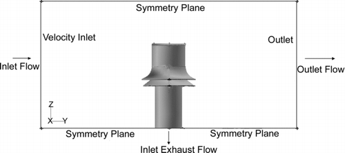
A box-shaped computational domain, , with length, width, and height dimensions of 1.07 m × 0.53 m × 0.53 m (42″× 21″× 21″), was created using GAMBIT 2.2.30 (ANSYS, Inc., Canonsburg, PA). A digitized model of the BSI-e was created and placed in the center of the domain with the top of the outer shell a distance of 178 mm from the top of the computation domain, and with the exit plane of the exhaust tube flush with the floor of the computation domain. The dimensions of the computation domain were selected to be sufficiently large to avoid excessive flow blockage in the simulated flow field. Sensitivity analysis (CitationLee et al. 2008) was carried out for different heights and widths to ensure that the velocity near the lateral boundaries did not exceed 110% of the free stream air velocity. The upstream surface of the computation domain was set to have a uniform velocity boundary condition, with a pressure of 101 kPa. Boundary condition of the top, bottom and the lateral surfaces of the domain were set to symmetry planes (no shear); the exhaust tube of the BSI-e model was set to have a fixed flow rate of 100 L/min; and the domain outlet boundary was set to be an “outflow” surface, i.e., a boundary that had a specified volumetric flow rate.
FIG. 2 Schematic of the computational domain used in numerical simulations. Boundary conditions: Inlet surface of the domain—“Velocity Inlet” (with velocity of wind speed); Lateral surfaces of the domain—“Symmetric”; Outlet surface of exhaust tube and domain—“Outflow” (with outlet flow rate of 100 L/min at exhaust tube); Surfaces of BSI-e—“Wall.”
2.2.2. Mesh Generation
Gambit 2.2.30 was used for mesh generation. Surface meshes were generated first, with weighting ratio and spacing factor adjusted to allow for higher mesh density in regions where greater velocity gradients were expected. Three-dimensional volume meshes were built based on surface meshes for various modules in the computational domain. Tetrahedron and prism boundary layer meshes were used in the 3-D mesh. High-resolution gridding in regions of possible large velocity gradients (e.g., near the rims of the shells) was employed. Grid sensitivity was tested by determining the change in the velocity field at select high velocity-gradient locations when the grid density was doubled. The final mesh density was sufficiently high such that the flow field results were unaffected by further mesh density increase (with less than 1% change in velocity when the mesh density was doubled). Overall, 4 million cells were constructed in the domain, with a minimum cell volume of 1.88× 10− 10 m 3 and a maximum cell volume of 1.01× 10− 6 m 3. These volume values are approximately the same as those of 0.6 mm and 10 mm cubes.
2.2.3. Turbulence Model
The use of a turbulence model in the CFD simulation was necessary because the Reynolds number based on the gap between the inner and outer shells could be greater than 5000 at a wind speed of 24 km/h. The seven-equation Reynolds Stress Model (RSM), which is a higher level, elaborate turbulence model for both internal and external complex flows, and accounts for the directional effects of the Reynolds stress fields (CitationBerlemont et al. 1990; CitationBurry and Bergeles 1993), was used for the BSI-e simulations. RSM, which is one of the most meticulous models in Fluent code, was set to be segregated, implicit, and steady for 3D simulation. The effect of mesh conditions on turbulent deposition simulation was taken into consideration; and, precautions were taken to ensure that near-wall resolution was sufficiently high (CitationParker et al. 2008).
The value of turbulence intensity at the inlet boundary was set at 5%, based on wind tunnel measurements (CitationLee et al. 2008). FLUENT uses a finite volume approach to solve the mass and momentum equations and the calculations were performed with double precision and with the numerical convergence criterion for continuity calculations set at ∼ 10− 6 for the 3-D simulations. To further ensure convergence, the simulations were run until velocities at computational locations were unchanged with 100 additional iterations.
After the flow field in the computation domain was established through CFD simulation, particle tracking was performed. The Discrete Phase and Particle Tracks module of the FLUENT program was used to simulate the particle trajectories. The presence of the particles was assumed to not affect the flow field. In this study, particle tracking with turbulent dispersion was carried out using the Stochastic Tracking model in FLUENT. The turbulent dispersion of particles was calculated using the instantaneous fluid velocity from flow field simulation. Time-dependent fluctuating velocity components were calculated based on the characteristic lifetime of eddies.
The particle concentration in the wind tunnel experiments of CitationNene (2006) and (CitationBaehl 2007) was about 109 m–3. For such aerosol concentration levels, Brownian and kinematic coagulation should be both negligible (CitationHinds 1999). Therefore, in the CFD simulation, particle-particle interactions were neglected. Particles with a density of 1000 kg/m3 and a specified diameter were released from locations that were uniformly distributed across the inlet surface of the computation domain. The FLUENT program would track each particle until it exited the computation domain or was deposited on a surface of the BSI-e model. The attachment coefficient between the particles and a wall was assumed to be unity, which corresponds to the expected behavior of the liquid aerosol droplets used in the experiments of CitationNene (2006) and CitationBaehl (2007). Drag force and gravity were included in particle tracking. Particle tracking examples were also carried out with the Saffman force included to check the effect of shear-induced lift; however, the Saffman force did not have a significant effect on aerosol deposition. As a consequence, the results reported herein were those with the Saffman force option in FLUENT turned off.
Based on the fate of all the particles that were tracked, a CFD-based penetration could be calculated for a given particle size at a given wind speed. The penetration could be dependent on the number of particles used in particle tracking due to numerical artifacts, unless a sufficient number of particles were used. Numerical tests showed that a minimum of 50,000 was needed to obtain particle-number-independent results; however, 400,000 particles were used in this study.
2.2.4. Computation of CFD-Based Penetration
The most critical check on the efficacy of the CFD simulations was to compare the particle penetration from CFD with the experimentally measured results of CitationNene (2006) and CitationBaehl (2007). Computation of the CFD-based penetration followed the physical definition of particle penetration as given in Equation (Equation1). In terms of the simulation results, that definition can be expressed as:
A root-mean-square normalized error, e rms, for the relative deviation between the numerical and experimental penetration results can be calculated from:
2.2.5. Regional Penetration and Deposition
The CFD results were utilized to determine regional particle deposition and penetration within the BSI-e. After the tracking particle trajectories with the CFD tools, terminal coordinates were obtained for the deposited particles. MatLab 2008a (The MathWorks, Inc., Natick, MA) was then used to plot the locations of particle deposition that were relevant to particle penetration through the inlet. The CFD results of regional deposition could not be compared with experimental data, as the latter were not available. However, the CFD results of regional deposition were used in developing the correlation between penetration and other dimensionless parameters.
Aspiration efficiency is commonly used in characterizing the performance of unidirectional sampling probes (CitationBelyaev and Levin 1974). Here, for the BSI-e, the aspiration efficiency was defined as the ratio of the concentration of a given particle size in the intake region where the aerosol flow enters the BSI-e between the rims of the two shells, to the concentration of that particle size in the free stream. The intake region is defined as a portion of the circumferential entrance surface that is bound by the rims of the shells, forming a 60° azimuthal angle () about the axis of the BSI-e, and symmetric with respect to the free stream velocity on the upwind side of the BSI-e. Based on particle tracking results, only the aerosol flow that traveled through the intake surface was able to reach the exhaust tube. Experimental measurements of the aspiration efficiency, P 1, would be very difficult, however P 1 could be computed based on CFD simulation using the following equation:
The penetration through the between-shell passage, P 2, was calculated from:
The flow rate through the exhaust tube was constant, so the penetration through tube, P 3, could be calculated using the following equation:
The independent variables in Equations (Equation4)–(Equation6) were calculated from CFD simulation results.
3. RESULTS AND DISCUSSION
3.1. Simulated Flow Field
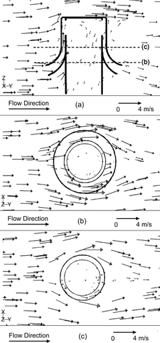
The flow field simulation results were qualitatively similar for the three different free stream velocities, so only the results for the wind speed of 8 km/h (2.22 m/s) are presented (). shows the air velocity in a vertical plane that cuts through the BSI-e axis and is parallel to the free stream; and show the velocity in two horizontal planes, the vertical locations of which are indicated in . All velocity vectors shown are their projections in the respective planes. With reference to , the aerosol flow enters the upwind side of the intake gap and is accelerated in the curved converging flow channel between the two shells, where it reaches a maximum speed of approximately 2.6 m/s, as compared with the free stream speed of 2.22 m/s. The flow first decelerates before entering the inlet, then accelerates in the curved converging gap between the shells. Recirculation zones can be observed near the entrance of the exhaust tube. The three views of show there is a split in the aerosol flow in the gap between the shells where the center portion on the upwind side follows up the slope of the bell-shaped shells and, the off-center portions flow around the waist of the bell-shaped shell and leave the gap between the shells on the downwind side. Most of the flow goes around the inner shell and is discharged at the downwind side, while part of the flow enters the openings (windows) between the roof of the outer shell and the entrance of the exhaust tube. Part of the flow exits through the downwind vertical openings and 100 L/min leaves through the exhaust tube.
FIG. 3 CFD simulation of the flow field at a wind speed of 8 km/h (2.2 m/s). (a) Velocity vectors in the vertical plane through the BSI-e axis and parallel to the free stream (dashed lines “b” and “c” indicate locations of the two horizontal planes for and ). (b) Velocity vectors in a horizontal plane slightly above the rim of the outer shell. (c) Velocity vectors in a horizontal plane in the cylindrical section of the shells (shell radii do not change with height). Units of velocity scales are m/s.
3.2. CFD-Based Particle Penetration Results
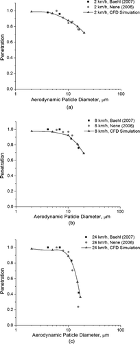
Aerosol penetration as a function of particle size and for wind speeds of 2, 8, and 24 km/h is shown in . The CFD-based penetration results not only have the proper trends, but they are also in excellent quantitative agreement with the experimental results. The root-mean-square normalized error, e rms calculated using Equation (Equation3) with all available experimental data, was 3.8%.
FIG. 4 Comparison of penetration from experiments of CitationNene (2006) and CitationBaehl (2007), and CFD simulations at wind speeds of: (a) 2 km/h. (b) 8 km/h. (c) 24 km/h.
The CFD-based penetration decreases with increasing particle size, and for the high inertia particles (e.g., 20 μ m AD), the penetration also decreases with increasing wind speed. These results agree with the expectation of penetration based on aerosol mechanics for situations where inertial impaction, as illustrated by deposition in the accelerating curvilinear flow region near the entrance to the BSI-e, would control the losses.
3.3. Penetration and Regional Particle Deposition
The three penetration terms, aspiration efficiency, P 1, penetration through the between-shell passage region, P 2, and penetration through the exhaust tube, P 3 (defined in Equations (Equation4)–(Equation6)), were calculated for 10 and 15 μ m AD particles and for wind speeds of 2, 8, and 24 km/h; and, the results are shown in . The aspiration, P 1, is approximately equal to or slightly greater than 1, where values greater than unity are apparently associated with subisokinetic sampling conditions (CitationBelyaev and Levin 1974; CitationHinds 1999). From and it may be observed that the flow decelerates just upstream of the BSI-e. Also, in , it may be noted that there is a divergence in flow away from the mean wind direction for the vectors just outside of the BSI-e on the upwind side, i.e., curvilinear flow in the x-y plane. This external flow deceleration effect tends to enrich the concentration of aerosol in the approximate intake region subtended by the 60° angle and the height between the shell rims.
TABLE 1 Estimated regional and overall penetration percentage of the BSI-e from CFD analyses
The penetration P 3 is near unity, suggesting that the particle losses in the exhaust tube are quite small. This is likely due to the low velocity in exhaust tube (less than 0.4 m/s in most cases) and there being no gravitational settling effect on particle deposition. P 2 had the lowest value among the three penetrations; it had approximately the same value as the overall penetration of BSI-e.
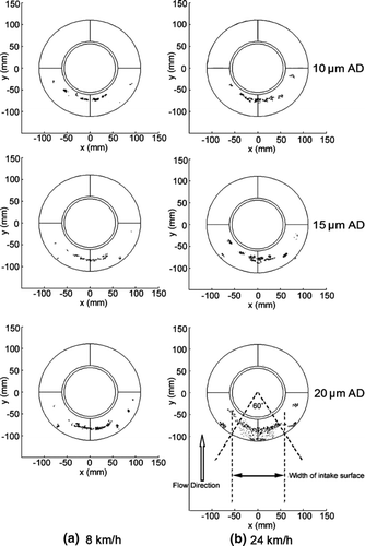
No particle deposition was found on the internal surface of the outer shell. However, significant particle deposition occurred on the curved surface of the inner shell. Deposition locations of various particle sizes on the inner shell are shown in and , for wind speeds of 8 and 24 km/h, respectively. The figures are top views of the inner shell, showing deposition locations of particles of 10, 15, and 20 μ m AD. Each dot in the views represents a deposited particle. Each view shows approximately 200–1000 deposited particles, from tracking a total of 400,000 particles that enter the upstream surface of the computational domain. The visualization results clearly show that most particle deposition was concentrated on an upwind area of the inner shell that lies within the angle of about 60°, and involves the sloped portion of the inner shell. Larger particle sizes and higher wind speeds cause the particles to deposit closer to the rim of the shell. Scattered particle deposition locations on the lateral side might be due to a turbulent effect at those localities where turbulence intensity values of over 65% were noted.
The number of particles deposited on the inner wall of the exhaust tube was typically about 10% of that deposited on the upwind side of the inner shell. This again shows that particle loss in the gap between the shells was the limiting factor of overall penetration of the BSI-e.
3.4. Importance of Gravitational Settling in the Between-Shell Passage
CFD simulation was also used to determine the importance of gravitational settling in particle deposition. The approach we used was to first conduct the particle tracking without including the gravitational force, and then repeat the calculations with gravity included. As shown in , at the higher wind speeds (8 and 24 km/h), the CFD-based penetration was essentially the same for all particle sizes whether gravity was considered or not. However, at the wind speed of 2 km/h, the gravitational effect was significant with the largest difference being about 8% in the case of 20 μ m AD particles. At low wind speeds, the gravitational effect is more significant because of the longer residence time of the particles in the sloped part of the between-shell passage. This may also explain why the penetration of intermediate particle sizes at the wind speed of 2 km/h can be lower than that at 8 km/h (), e.g., the penetration of 10 μ m AD particles is 87.5% at 2 km/h, and 94.4% at 8 km/h.
TABLE 2 CFD predictions of overall penetration percentage of the BSI-e with and without the gravitational effect
3.5. Semi-Empirical Correlation of Penetration and Dimensionless Numbers
Assuming that impaction and gravitational settling are the most important factors affecting aerosol penetration through the BSI-e, a semi-empirical correlation equation similar to that utilized in filtration theory (CitationHinds 1999) can be constructed to relate overall penetration to a Stokes number, Stk, a dimensionless gravitational settling parameter, G, and a velocity ratio, r, which provides a correction to the first two dimensionless numbers. Assume the form of the correlation to be:
The Stokes number, Stk, is defined as:
The gravitational settling parameter, G, is defined as (CitationHinds 1999):
The velocity ratio, r, is defined as:
The impaction and gravitation settling effects are functions of the between-shell air velocity, which depends on the free stream velocity, and the aerosol sample flow rate. Since Stk and G use the free stream velocity, it is necessary to modify the results through the use of the velocity ratio. CitationNene (2006), in his experimental study of the BSI-e, proposed an empirical correlation that included a Stokes number and a velocity ratio but it did not include the gravitational settling factor. In the study of a cap-and-funnel type omni-directional aerosol inlet, CitationLee et al. (2008) had proposed an empirical equation that only included a Stokes number. The semi-empirical equation generated in this study, which includes the three dimensionless numbers, takes into account both inertial deposition and gravitational settling. Including the velocity ratio is essentially equivalent to including a Reynolds number (based on the free stream velocity) in the correlation.
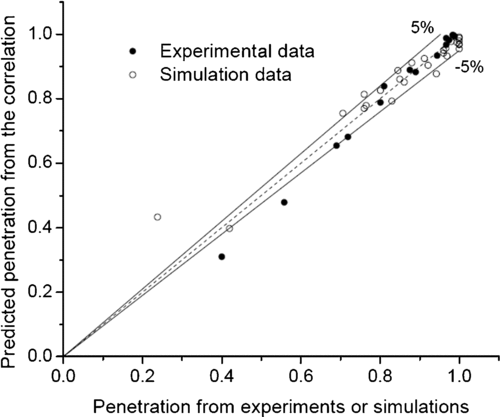
Using the experimental and CFD-based data, curve fitting with the OriginPro 7.5 software provided the correlation coefficients for Equation (Equation7), which are shown in . With reference to , the fitted curves for the three wind speeds are in excellent agreement with the experimental and CFD penetration data, especially for the lower Stokes number cases.
FIG. 6 Curves showing penetration predicted from correlation compared with experimental and CFD data at wind speeds of (a) 2 km/h, (b) 8 km/h, (c) 24 km/h.
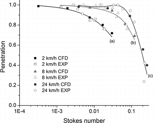
TABLE 3 Curve fitting results for the coefficients in Equation (Equation7) with corresponding uncertainties
shows the agreement of the penetration predicted from Equation (Equation7) with the experimental and CFD penetration values. Note that there are two data points, which are associated with the smallest abscissa values on the 24 km/h curve, that have large errors. The slope of the penetration curves through these two data points, , is steep so a small uncertainty in the abscissa value, e.g., experimentally measured particle size or correlation fit to the numerical data, results in a large relative deviation between the experimentally measured or numerically calculated penetration and the prediction from the correlation. The root-mean-square relative error of the fitting is 3.8% with the two outlying data points removed; however, it is 13.5% when all data points are included. Omission of the two data points, which are associated with particle sizes ≥ 15 μ m AD, is not a critical concern for most applications where a pre-separator with a cutpoint ∼ 10 μ m AD would be included in the overall inlet system; and, as the penetration for those points is 20–40%, such particles would mostly be eliminated by the pre-separator.
4. SUMMARY AND CONCLUSIONS
In this study, flow field simulations and particle tracking were carried out for the entrance section of a 100 L/min omni-directional Bell-Shaped Inlet that is used for sampling ambient aerosol. Neither an insect screen nor a large-particle pre-separator was included with the inlet. For wind speeds of 2, 8, and 24 km/h, particles that penetrate through the inlet are primarily associated with flow that enters the inlet through an intake region defined by the rims of the shells and a 60° azimuthal angle that is symmetric to the central free stream velocity vectors on the upwind side of the inlet.
Particle penetration results based on the CFD simulations were in excellent agreement with experimental results provided by previous studies. The root mean square normalized standard error, from comparing the simulation results with a body of experimental data for wind speeds of 2, 8, and 24 km/h, was 3.8%. In-depth analysis of the CFD simulation results revealed that particle deposition took place principally on the inner shell in a region where the flow was curvilinear and accelerating as it changed direction from horizontal to vertical. Although inertial impaction was the dominant mechanism of particle deposition, gravitational settling was found to have a significant effect on particle deposition at the lowest wind speed tested (2 km/h).
Based on the knowledge of regional particle deposition and the dominant deposition mechanisms, a six-parameter semi-empirical correlation equation was constructed to predict the penetration through the inlet. The correlation uses a Stokes number based on the free stream velocity and the width of the intake gap at the flow entrance to the BSI-e, a dimensionless gravitational settling parameter, and a velocity ratio for correction of the first two dimensionless numbers.
The findings of this study demonstrate the value of CFD modeling in the design of omni-directional aerosol inlets. CFD simulation can provide information that is difficult to acquire through experimental investigations, such as regional distribution of particle deposition and the importance of specific deposition mechanisms. Such information can then be used in the development of semi-empirical correlation equations, which should be valuable for optimizing designs of inlet entrance devices. Also, the correlation should allow designers to predict the performance of an integrated inlet that may also include a screen and a pre-separator with known penetration characteristics.
Financial support for this study was provided under US Army contracts W911SR-07-C-0056 and W911SR-08-C-0019. The authors are grateful to Drs. Edward Stuebing and Jerold Bottiger at Edgewood Chemical and Biological Center for providing guidance and support for research activities carried out under these contracts. The authors also thank Dr. Shishan Hu and Dr. Sridhar Hari for valuable discussions on CFD simulation, and Messrs. Rohit Nene and Michael Baehl for their previous efforts in wind tunnel testing.
References
- Baehl , M. M. 2007 . Ambient Aerosol Sampling Inlet for Flow Rates of 100 and 400 L/min , M. S. Thesis College Station, Texas : Department of Mechanical Engineering, Texas A&M University .
- Belyaev , S. P. and Levin , L. M. 1974 . Techniques for Collection of Representative Aerosol Samples . J. Aerosol Sci. , 5 : 325 – 338 .
- Berlemont , A. , Desjonqueres , P. and Gouesbet , G. 1990 . Particle Lagrangian Simulation in Turbulent Flows . Int. J. Multiphase Flow , 16 : 19 – 34 .
- Bisgaard , H. 1995 . A Metal Aerosol Holding Chamber Devised for Young Children with Asthma . Eur. Respir. J. , 8 : 856 – 860 .
- Burry , D. and Bergeles , G. 1993 . Dispersion of Particles in Anisotropic Turbulent Flows . Int. J. Multiphase Flow , 19 : 651 – 664 .
- Chandra , S. and McFarland , A. R. 1997 . Shrouded Probe Performance: Variable Flow Operation and Effect of Free Stream Turbulence . Aerosol Sci. Technol. , 26 : 111 – 126 .
- Gao , P. F. , Dillon , H. K. , Baker , J. and Oestenstad , K. 1999 . Numerical Prediction of the Performance of a Manifold Sampler with a Circular Slit Inlet in Turbulent Flow . J. Aerosol Sci. , 30 : 299 – 312 .
- Gong , H. , Anand , N. K. and McFarland , A. R. 1993 . Numerical Prediction of the Performance of a Shrouded Probe Sampling in Turbulent Flow . Aerosol Sci. Technol , 19 : 294 – 304 .
- Gong , H. , Chandra , S. , McFarland , A. R. and Anand , N. K. 1996 . A Predictive Model for Aerosol Transmission Through a Shrouded Probe . Environ. Sci. Technol , 30 : 3192 – 3198 .
- Hinds , W. C. 1999 . Aerosol Technology: Properties, Behavior and Measurement of Airborne Particles, , 2nd ed , New York : Wiley-Interscience .
- Hu , S. and McFarland , A. R. 2007 . Numerical Performance Simulation of a Wetted Wall Bioaerosol Sampling Cyclone . Aerosol Sci. Technol. , 41 : 160 – 168 .
- Lee , S. R. , Holsen , T. M. and Dhaniyala , S. 2008 . Design and Development of Novel Large Particle Inlet for PM Larger than 10 μ m (PM > 10) . Aerosol Sci. Technol. , 42 : 140 – 151 .
- Liu , B. Y. H. and Pui , D. Y. H. 1981 . Aerosol Sampling Inlets and Inhalable Particles . Atmos. Environ. , 15 : 589 – 600 .
- McFarland , A. R. , Ortiz , C. A. , Moore , M. E. , DeOtte , R. E. and Somasundaram , S. 1989 . A Shrouded Aerosol Sampling Probe . Environ. Sci. Technol. , 23 : 1487 – 1492 .
- McFarland , A. R. , Rodgers , J. C. , Ortiz , C. A. and Moore , M. E. 1992 . A Continuous Sampler with Background Suppression for Monitoring Alpha-Emitting Aerosol-Particles . Health Phys. , 62 : 400 – 406 .
- McFarland , A. R. , Wedding , J. B. and Cermak , J. E. 1977 . Large Particle Collection Characteristics of Ambient Aerosol Samplers . Environ. Sci. Technol. , 11 : 387 – 390 .
- McKinnon , A. D. , Bowyer , S. M. , Hubbard , C. W. , Miley , H. S. , Perkins , R. W. , Thompson , R. C. and Warner , R. A. 1998 . Environmental Measurements with a Comprehensive Nuclear Test Ban Treaty Radionuclide Particulate Monitor . J. Radioanalytical Nucl. Chem. , 235 : 115 – 119 .
- McMurry , P. H. 1999 . A Review of Atmospheric Aerosol Measurements . Atmos. Environ. , 34 : 1959 – 1999 .
- Nene , R. R. 2006 . Design of Bio-aerosol Sampling Inlets , M. S. Thesis College Station, Texas : Department of Mechanical Engineering, Texas A&M University . Available online at: http://txspace.tamu.edu/handle/1969.1/5736?show=full
- Parker , S. , Foat , T. and Preston , S. 2008 . Towards Quantitative Prediction of Aerosol Deposition from Turbulent Flows . J. Aerosol Sci. , 39 : 99 – 112 .
- Pleil , J. D. , Mcclenny , W. A. , Holdren , M. W. , Pollack , A. J. and Oliver , K. D. 1993 . Spatially Resolved Monitoring for Volatile Organic-Compounds Using Remote Sector Sampling . Atmos. Environ. , 27 : 739 – 747 .
- Weber , D. J. and Wise , D. G. 1997 . Computational Fluid Dynamics Modeling: Wind Tunnel Wall Effects and Aerosols AIAA Technical Papers Part 2, A96 -31695 08-02. American Institute of Aeronautics and Astronautics Applied Aerodynamics Conference, Atlanta, GA, June 23–25, 1997
- Wedding , J. B. , Weigand , M. , John , W. and Wall , S. 1980 . Sampling Effectiveness of the Inlet to the Dichotomous Sampler . Environ. Sci. Technol. , 14 : 1367 – 1370 .
- Witschger , O. 2000 . Sampling of Airborne Dusts in Workplace Atmospheres . Kerntechnik , 65 : 28 – 33 .
