Abstract
Due to the increasingly widespread use of engineered nanoparticles and the increasing number of persons handling them, there is a need to monitor the personal exposure of these persons. Current gravimetric and optic methods are rather insensitive for nanoparticles ( <∼ 100 nm), and therefore not suitable for this task. To help solve this problem, we have miniaturized an instrument capable of measuring nanoparticles developed earlier by our group; the diffusion size classifier (DiSC). The instrument is now handheld (4 × 9 × 18 cm), and can easily be used for personal exposure monitoring, opening up applications for workplace exposure monitoring (for engineered nanoparticles but also for traditional workplace aerosols such as welding fumes or combustion exhaust) and medical studies. The DiSC measures the particle number concentration and the average particle diameter of an aerosol, however, like most simple instruments, it is nonspecific, i.e., it detects all nanoparticles and cannot distinguish between background aerosol and specific engineered nanoparticles. In this paper, we first present the instrument design and the calibration procedure for the miniature DiSC, followed by some results from comparisons with traditional aerosol instruments in the field.
1. INTRODUCTION
Engineered nanoparticles have novel properties (electronic, optic, catalytic, etc.) due to their small size. Besides some traditional uses (TiO2 particles in paints, cosmetics and sunscreens, carbon black as additive for tires or printer toner), a lot of new applications have been proposed or realized which exploit the specific properties of nanoparticles—for example their higher catalytic efficiency (e.g., cerium oxide particles as fuel-borne catalysts), increased permeability through biological barriers (drug delivery), different optical properties (tunable absorption by particle size changes), and so on. Nanoparticles are being incorporated into composites to improve material properties; in particular, carbon nanotubes with their excellent electrical conductivity and mechanical strength have promising applications. Silver nanoparticles have toxic properties which can be exploited in the medical sector but also in consumer products such as clothing that will not smell of sweat, or paints for building facades that have antialgal and antifungal properties.
Along with the larger number of available engineered nanoparticles and their applications, their potential detrimental health effects have received more attention. Airborne nanoparticles appear most critical, because of their easy uptake pathway through airways and lung. In particular, people handling these materials or working in plants where nanoparticles are being fabricated or processed are at risk of exposure. Because leaks in such plants are likely to be localized, stationary measurement equipment might not be at the right location to detect a leak, and a wearable device to measure the personal exposure is preferable. The nuclear industry has developed a tool for this purpose: the dosimeter. It is worn by potentially exposed persons, and their dose is monitored regularly. The need for similar tools in the nanoparticle industry is clear (CitationNel et al. 2006), and the development of a universal aerosol sampler for airborne nanostructure materials has been proposed as one of five big challenges on the road to safe nanotechnology, namely, such a universal sampler should be able to measure number, surface, and mass concentrations simultaneously, since it is not obvious which metric should be employed (CitationMaynard et al. 2006). Toxicological studies suggest that particle surface area is best related to health effects (CitationAitken et al. 2006). Microscopically, this can be intuitively understood, at least for biopersistent particles: the particle surface is the area where interactions with the body take place, and it thus is to be expected that health effects scale with available particle surface area.
An ideal personal sampler would be robust, small, light, and cheap; it should be a direct-reading instrument to provide an alarm capability and finally it should be able to distinguish the ubiquitous background aerosol from the specific engineered nanoparticles in question (e.g., carbon nanotubes that may pose similar health risks as asbestos fibers). Unfortunately, this wish list is far from today's reality: a distinction between background aerosol and specific engineered nanoparticles is often only possible with more complex offline measurements such as TEM sampling or chemical analysis of filter samples. Currently available personal samplers for aerosols operate on a mass basis, either by direct gravimetric measurements, or by interpreting light scattering as particle mass. For nanoparticles, both methods are quite insensitive: Personal gravimetric measurements are limited by the size of the pump and its battery that a worker can be expected to carry; at flow rates of ∼2 lpm, one work shift (8 h) results in a sampled air volume of approximately 1 m3. Even with filter conditioning, weighing errors due to water uptake are on the order of 10 μg, which means that personal gravimetric measurements have errors of ∼10 μg/m3, and are not sensitive enough to detect typical ambient PM. Furthermore, this technique gives no real-time information—a person exposed to high levels of nanoparticles will only realize this later, when the filter sample has been processed. In contrast, light scattering sensors are direct reading instruments, capable of sounding an alarm if high levels of particulate matter are detected. However, for particles smaller than approximately half the wavelength of the light used, the scattering intensity scales with the particle diameter d as d 6, i.e., at constant particulate mass per air volume the light scattering intensity scales with d 3 for small particles—which means that the light scattering intensity drops very rapidly for particles <∼0.3 μm—light-scattering based instruments go blind for small particles. In contrast to light scattering, the absorption of light is proportional to particle mass. Aethalometers measure the absorption of light by particles collected on a filter. Very recently, a miniature Aethalometer—about the size of two cigarette packs—has been commercialized (Magee Scientific Model AE51 microAeth). The drawback of this type of instrument is that it only measures light-absorbing particles, in particular particles containing black carbon. Overall, this means that presently no simple and small instruments are commercially available that can reliably measure all ultrafine particles.
To close this gap in aerosol instrumentation, the focus of current research has shifted to electrical methods, because nanoparticles can easily be charged. Two examples of recent developments with potential for miniature instruments are the tailored electrode concentration sensor (CitationRanjan and Dhaniyala 2009) and the miniature disk electrostatic aerosol classifier (CitationLi et al. 2009). Commercially, Grimm Aerosoltechnik GmbH has recently introduced the Model 1.320 nanoCheck, while Philips Aerasense has introduced the nanoTracer (CitationMarra et al. 2010).
Our research group invented the Diffusion Size Classifier (DiSC, Fierz et al. 2008), a simple instrument to measure the particle number concentration and the average particle diameter. More recently, we have demonstrated a prototype of a handheld diffusion charger (CitationFierz et al. 2009). Our latest development is a combination of the two, a handheld, battery-powered DiSC. We have built a first small series of 10 of these instruments. This article describes the instrument and presents some sample results that we have obtained with it.
2. THEORY OF OPERATION
The Diffusion Size Classifier (DiSC) is a simple instrument based on unipolar charging of the aerosol, followed by detection in two electrometer stages. It has been described in detail in an earlier publication (CitationFierz et al. 2008). A schematic overview of the instrument is given in . Very briefly, aerosol is first charged in a standard positive unipolar diffusion charger, which imparts an average charge ![]() on the particles that is approximately proportional to the particle diameter. More accurately,
on the particles that is approximately proportional to the particle diameter. More accurately, ![]() is usually fitted with a power-law function (e.g., CitationFierz et al. 2002; CitationJung et al. 2005):
is usually fitted with a power-law function (e.g., CitationFierz et al. 2002; CitationJung et al. 2005):
FIG. 1 Schematic overview of the miniature DiSC: Aerosol is charged in a unipolar corona charger which controls the charging current, excess ions are removed in the ion trap, and the charged aerosol is measured in two electrometer stages (D = diffusion stage, F = filter stage), allowing for particle sizing and counting.

By substituting Equation (Equation1) for ![]() and solving for N, the particle number concentration is obtained.
and solving for N, the particle number concentration is obtained.
3. DESIGN CONSIDERATIONS
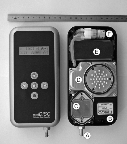
The overruling design decision for the miniature DiSC was to minimize size and weight as far as possible so that it could be used for personal exposure monitoring; additionally, we attempted to make it easy to use with a built-in rechargeable battery and by storing data to a standard SD-card. Compared to the original desktop version of the DiSC, the new version has shrunk in size and weight by a bit more than a factor of 10: it now measures only 4 × 9 × 18 cm, and weighs 670 grams. This miniaturization was made possible by a heavily optimized instrument design, but also by a number of size-to-performance tradeoffs, such as shorter battery lifetime, shorter service intervals, and a lower flow rate leading to higher detection limits. The reduction of size and weight was achieved to a large part by moving from an instrument case with individual components in its interior to a unibody design, where the instrument is machined from a solid block of aluminum, eliminating the need for a case (). Furthermore, all components were reduced in size as far as possible. To reduce power consumption, the flow was reduced from 1.5 lpm to 1 lpm, and a high-voltage module with low power consumption was used. Power consumption overall was lowered from about 6 W to below 3 W and thus a smaller battery pack can now be used while still delivering a reasonable operating time of ∼8 h. The diffusion and filter stages were slightly reduced in size, which has a small negative impact on the instrument performance: the geometry of the diffusion stage screens (wire diameter, wire spacing, screen diameter) determines the particle deposition in the diffusion stage. Particles are not only deposited by diffusion alone, but also by other mechanisms such as impaction. The combination of deposition mechanisms leads to a diameter of maximum penetration ![]() (see in the calibration section below), which depends on the stage geometry, and can be optimized for a large
(see in the calibration section below), which depends on the stage geometry, and can be optimized for a large ![]() (CitationFierz et al. 2009). Particle size determination is only possible if the particle size range is restricted to
(CitationFierz et al. 2009). Particle size determination is only possible if the particle size range is restricted to ![]() , because otherwise there is no unique relation between R and d. When the diffusion stage diameter is reduced, the gas velocity in the stage increases, and this leads to increased impaction and correspondingly to a smaller
, because otherwise there is no unique relation between R and d. When the diffusion stage diameter is reduced, the gas velocity in the stage increases, and this leads to increased impaction and correspondingly to a smaller ![]() . In our instrument design,
. In our instrument design, ![]() is about 0.5 μm. For most ambient aerosols, the contribution of particles with diameters
is about 0.5 μm. For most ambient aerosols, the contribution of particles with diameters ![]() to the electrometer signals is negligible, since their number is typically low, and the particle charge scales approximately with d
1. However, in dusty environments, large particles can dominate the signal, and both the diameter and number computation can be quite wrong. To alleviate this problem, we have constructed an impactor with a 50% cutoff size of about 0.8 μm which screws into the inlet port of the instrument. This impactor eliminates most of the larger particles that would lead to erroneous measurements. The limiting factor for the impactor cutoff is the maximal pressure drop that the pump can achieve, which is quite low in the miniature DiSC (∼10 hPa).
to the electrometer signals is negligible, since their number is typically low, and the particle charge scales approximately with d
1. However, in dusty environments, large particles can dominate the signal, and both the diameter and number computation can be quite wrong. To alleviate this problem, we have constructed an impactor with a 50% cutoff size of about 0.8 μm which screws into the inlet port of the instrument. This impactor eliminates most of the larger particles that would lead to erroneous measurements. The limiting factor for the impactor cutoff is the maximal pressure drop that the pump can achieve, which is quite low in the miniature DiSC (∼10 hPa).
4. CALIBRATION
4.1. Experimental Instrument Calibration
The miniature DiSC is calibrated by challenging it with quasi-monodisperse NaCl aerosol exiting a DMA. Our standard calibration covers the size range from 20 to 240 nm. During the calibration, the miniature DiSC is operated in parallel with a CPC. The two stage currents ![]() and
and ![]() are recorded along with the CPC number concentration. The calibration setup is depicted in .
are recorded along with the CPC number concentration. The calibration setup is depicted in .
FIG. 3 Calibration setup for the miniature DiSC: a NaCl solution is nebulized, particles are size-selected in a DMA, neutralized, and then detected in parallel by the CPC and miniature DiSC.

By choosing the particle size distribution of the calibration aerosol sensibly (i.e., with a low mean diameter of ∼50 nm), the number of doubly charged particles is kept below 10% throughout the entire calibration size range. shows the measured diffusion stage penetration for particles in the size range of 20–2400 nm. The size range 20–240 nm was covered with the standard calibration setup described above. For larger particles, the DMA is no longer suitable due to large fractions of multiply charged particles. Therefore, we produced quasi-monodisperse DEHS (Bis(2-ethylhexyl) sebacate; C26H50O4) aerosol with a TSI model 3475 condensation monodisperse aerosol generator. The DEHS particle size range was varied from approximately 0.7 to 2.5 μm diameter. The particle size distribution was measured with an APS (TSI model 3321), which showed that the geometric standard deviation of the DEHS aerosol was typically σ g = 1.2.
FIG. 4 Theoretical and experimental diffusion stage penetration. The theoretical curves are calculated with and without image charge effect. The diameter of maximal penetration d![]()
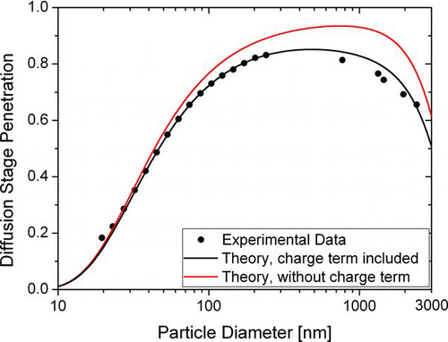
The penetration of a diffusion stage can be calculated with fan filter theory (CitationCheng and Yeh 1980). The theoretical prediction including diffusion, impaction, interception and diffusion-enhanced interception is shown in grey in . It differs significantly from the measured values. The agreement can be improved by adding an image-force induced deposition term with a single-fiber efficiency η given by
The diameter of maximal penetration ![]() is ∼500 nm, which has implications for the instrument performance: from , we can see that 2 μm particles have the same current ratio R as 75 nm particles. However, these particles carry an average charge which is approximately forty times higher than that of 75 nm particles. Hence, one 2-micron particle will be detected as forty 75 nm particles. This calculation illustrates the need for an inlet conditioner in environments with many coarse particles.
is ∼500 nm, which has implications for the instrument performance: from , we can see that 2 μm particles have the same current ratio R as 75 nm particles. However, these particles carry an average charge which is approximately forty times higher than that of 75 nm particles. Hence, one 2-micron particle will be detected as forty 75 nm particles. This calculation illustrates the need for an inlet conditioner in environments with many coarse particles.
4.2. Calculated Calibration for Polydisperse Aerosols
After the calibration process, the instrument response for monodisperse particles is known. This monodisperse calibration can then be used to calculate the current ratio Rpoly for any arbitrary polydisperse size distribution dN/dlogd as follows:
Once Rpoly has been calculated numerically for lognormal size distributions of a given σ g and varying d, we use a polynomial fit to describe the geometric mean diameter dGM of the lognormal distribution as follows:
The calibration constants (ai , c′, x) are stored on the instrument to display particle diameters and concentrations online. This data inversion procedure introduces small errors because the polynomial fit does not exactly reproduce the experimentally measured calibration curve. However, these errors are small (typically <5%) compared to the uncertainty incurred by the unknown shape of the particle size distribution, discussed in the next section.
4.3. Influence of the Shape of the Particle Size Distribution
To understand the influence of the shape of the particle size distribution on the instrument response, we performed simulations where the instrument response was calculated for a particle size distribution different than the one the instrument was calibrated for, and then the data inversion algorithm was applied. We did this for two model cases:
| 1. | a monomodal lognormal size distribution, with mean particle diameter fixed at 70 nm, concentration fixed at 1000 pt/ccm, and varying σ g between 1.1 and 2.9. | ||||
| 2. | a bimodal lognormal size distribution; with an accumulation mode of 1000 pt/ccm at 100 nm with σ g = 1.7, and nucleation mode at 20 nm with σ g = 1.5 with varying amplitude of 0 – 3 × 10⁴ pt/ccm. | ||||
Naturally, not all possible size distribution shapes can be examined, but these examples should give a general feeling for what will happen if the particle size distribution is different than assumed. The results are summarized in Tables and .
TABLE 1 Computed miniature DiSC response to a lognormal aerosol size distribution (N= 1000 pt/cm3, d= 70 nm) with varying geometric standard deviation σ g
TABLE 2 Computed miniature DiSC response to bimodal lognormal aerosol size distribution with a fixed accumulation mode at 100 nm and a varying nucleation mode at 20 nm. The diameter reported for the particle size distribution is the geometric mean diameter
From the two tables we see that the calculated average particle diameter is much more sensitive to the shape of the particle size distribution than the calculated particle number. For the broader particle size distributions with σ g > 2, the particle diameter is clearly overestimated, in the most extreme case by 65%. The particle number determination appears to be quite robust, and the (simulated) error never exceeds 20%. In reality, due to losses of small particles in the unipolar charger (see section 5.1., larger errors are to be expected if a significant amount of particles is below ∼15 nm diameter.
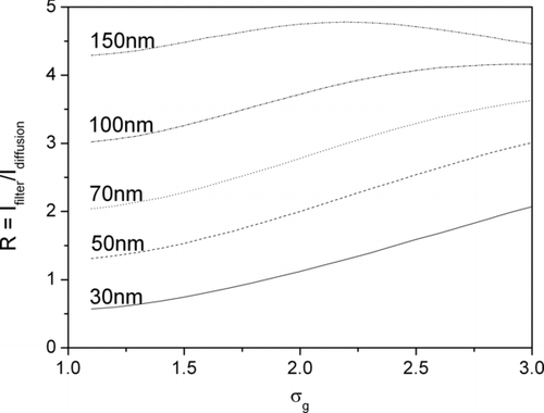
Another way of describing the influence of the width of the particle size distribution is shown in . Here, the calculated current ratio ![]() is plotted for 5 lognormal size distributions with different mode and varying σ
g
. With the help of this graph, the influence of the width of the particle size distribution can be assessed: as an example, we note that by inspection for σ
g
= 2.0, a 10% error in estimating σ
g
results in an error of approximately the same magnitude in diameter.
is plotted for 5 lognormal size distributions with different mode and varying σ
g
. With the help of this graph, the influence of the width of the particle size distribution can be assessed: as an example, we note that by inspection for σ
g
= 2.0, a 10% error in estimating σ
g
results in an error of approximately the same magnitude in diameter.
4.4. Lung-Deposited Surface Area Calibration
For particles smaller than ∼0.3 μm, a good correlation has been found between lung-deposited surface area of the particles (LDSA) and the signal of a diffusion charger (TSI model 3550 NSAM) both for the alveolar (A-LDSA) and tracheobronchial (TB-LDSA) parts of the lung (CitationAsbach et al. 2009). The lung-deposited surface area concentration is defined as the particle surface area concentration per unit volume of air, weighted by the deposition probability in the lung. The deposition probability is customarily calculated according to the ICRP report 66 (ICRP 1994). LDSA is an interesting quantity, because it captures the toxicologists’ idea that particle surface area available in the lung is a relevant exposure metric.
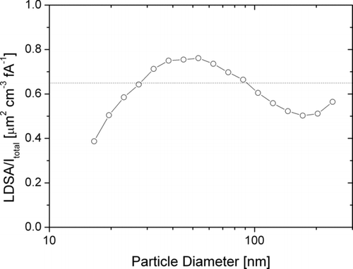
The good correlation of LDSA with the charge acquired in diffusion charging mainly relies on the fact that LDSA is nearly proportional to d 1 for particles in the size range of 10 to 300 nm, as is diffusion charging. Therefore, the correlation exists for any diffusion charger which does not exhibit high particle losses in the charger, and the miniature DiSC is no exception. shows the calculated A-LDSA divided by the total current in the miniature DiSC for particle sizes between 16 and 240 nm. This size range typically contains the majority of the lung-deposited surface area for ambient aerosols. Although the particle diameter is varied by more than an order of magnitude, the ratio remains within 20% of 0.65 μm2 cm−3 fA−1; i.e., the total current Itotal measured by the instrument is a good approximation of the lung-deposited surface area, even without any further diameter-dependent corrections. For particles larger than about 400 nm, the LDSA is severely underestimated by Itotal . However, under normal ambient conditions the contribution of these larger particles to the total surface area is small. Therefore we can conclude that the LDSA can be estimated with reasonable accuracy using the miniature DiSC.
5. INSTRUMENT PERFORMANCE
We discuss the performance of the miniature DiSC in three separate sections. First, the performance of two key components—the unipolar corona charger and the electrometer—is analyzed. Then, the performance of the instrument is compared to traditional instruments in a field campaign.
5.1. Unipolar Charger Performance
The stable functioning of the unipolar charger is crucial for the stability of any instrument based on unipolar charging. Therefore, we give a quick overview of the performance of our unipolar charger. The charger is a standard diffusion charger (); it employs a positive corona and occupies about 90 × 55 × 40 mm3 of the instrument volume (including electronics such as high voltage supply and charging current feedback control). The corona region is separated from the aerosol flow by a wire mesh, to keep the electrical field in the charging zone low. The charging current is measured on a counterelectrode kept at a low negative voltage, which draws the ions into and then through the aerosol flow. The charging current is regulated to 10nA by adjusting the corona high voltage appropriately. Unipolar chargers can be characterized by their Nit-product; Ni is the ion concentration in the charger, and t the aerosol residence time in the charger. Our charger's Nit-product can be estimated from the charging current, the charger geometry, the electric field between mesh and counterelectrode, and the gas flow rate. A direct computation of the Nit-product based on the parameters above yields an estimate of Nit= 7.5 × 10¹² m−3s. However, we expect a small amount of field penetration from the corona high voltage through the wire mesh into the charging zone. This field penetration is hard to quantify, but it will lower the Nit-product.
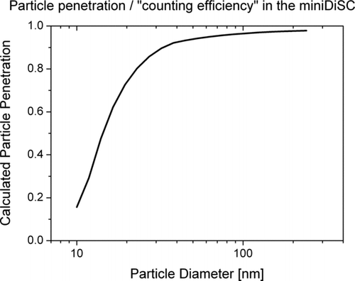
The charger's ion trap removes the excess ions in an electric field. Like any ion trap, it also removes small charged particles due to their high electrical mobility. By assuming a plug flow in the trap, we can calculate the particle losses due to the ion trap. The result of this calculation is shown in . This penetration curve looks similar to CPC counting efficiency curves, and referring to these we estimate that the miniature DiSC has a d 50 cutoff of ∼14 nm. However, it should be noted that the losses are partially calibrated for (see below).
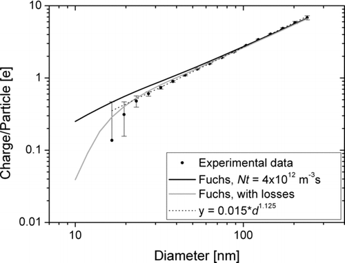
Experimentally, the charging efficiency is measured during the calibration process. We correct the measured charging efficiency for doubly-charged particles (the correction is small, i.e., <∼5% because the number of doubly-charged particles is kept below ∼10%). An example of a measured charging efficiency is shown in . Error bars are based on electrometer noise levels. The experimentally measured charging can be compared to theoretical calculations of unipolar diffusion charging. The most commonly used theory for this is Fuchs’ limiting sphere approach (CitationFuchs 1963; for a more accessible version see CitationBiskos et al. 2005) with corrections by CitationHoppel and Frick (1986). We calculated the theoretical charge per particle with Fuchs theory for Nit= 4 × 10¹² m−3s. Further parameters used in this calculation are: ϵ particle = 5; Mion = 109 amu, Zion = 1.4 cm2s−1; the ion properties are taken from CitationPui et al. (1988). By multiplying the Fuchs charging efficiency with the calculated charger loss, we get a reasonable agreement between theory and experiment. In spite of the noticeable losses in the charger, the power-law fit to the experimental data remains very reasonable down to about 20 nm, i.e., the losses are accounted for in the calibration. For particles smaller than about 20 nm, the losses are larger than what is allowed for in the calibration, and the instrument underestimates particle number concentrations for such particles.
FIG. 8 Experimentally determined charging efficiency as function of particle diameter; theoretical charging calculated according to Fuchs theory for an N i t-product of 4 × 10¹² m−3s, with and without calculated losses in the charger; and the power-law fit to the experimental data.
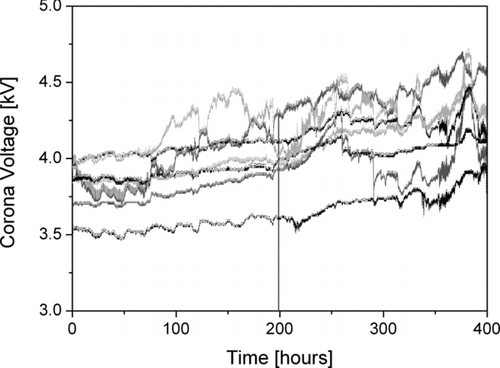
A further important point that is often neglected in the charger literature is the long-term behavior of the unipolar charger. Corona tips and wires age during operation, and acquire a coating of silicon dioxide which progressively reduces the corona current for a given corona voltage (CitationDavidson and McKinney 1998). Therefore, some form of compensation for this corona fouling is necessary. In our case, the corona high voltage is increased as described above. During a long-running instrument intercomparison experiment we measured the typical voltage increase over time (). For the seven instruments, we find a corona voltage increase of 1.0 ± 0.4 V/h. The instruments have a maximal corona voltage of ∼5.5 kV, so we expect typical cleaning intervals of the corona wire to be between 1000–2000 h of operation.
5.2. Electrometer Performance
Electrometer performance is critical for instruments relying on low-level current measurements. The instrument response time is given by the electrometer rise time, which for our design is ∼1.5 s (10–90% rise time). Electrometer measurement inaccuracies determine the lower detection limit of the instrument; these inaccuracies stem from both noise and zero offsets. The zero offsets might drift, leading to a systematic error in the measurement, while the electrometer noise leads to a statistical error in the measurement. Ideally, both components should be minimal.
In our electrometer design, the main source of zero offset error is the temperature-dependence of the zero offset. To minimize this drift, the miniature DiSC stages are heated to a controlled temperature of ∼30°C. The absolute values of the zero offsets are typically lower than 5 fA. When the instrument is turned on, it first warms up for five minutes, then it measures the zero offsets and subtracts them from subsequent measurements, providing a built-in auto zeroing at startup. Electrometer noise is also an important issue, in particular for a handheld instrument which is meant to be carried around on person, and which may thus be subject to sudden accelerations/shocks which are likely to increase the noise.
Both the accuracy of the automatic zero offset compensation and the electrometer noise can be checked by measuring with a HEPA filter at the inlet of the instrument. We performed the following experiment: four instruments measured filtered air for 10 min each. The instruments were first placed on a table (stationary), and then all packed in the same backpack which was carried around by a walking individual for another 10 min (mobile). Because each instrument contains two electrometers, these measurements gave us 16 individual 10 min electrometer stage records with a time resolution of one second, the averages of which are the zero offsets (which should all be zero). One typical measurement is shown in .
FIG. 10 Electrometer signal as function of time during stationary sampling of HEPA-filtered air. The standard deviation of this sample is 0.145fA (approximately the average of our 16 samples), the average (zero offset) of the sample is –0.033fA.
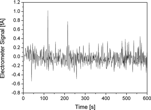
We found the average compensated zero offset to be Z= –0.074 fA with a standard deviation of 0.104 fA; the largest absolute value was an offset of –0.293 fA.
The noise level is computed as the standard deviation of the 600 data points of each measurement. The average noise level for the 8 stationary measurements was 0.145 fA, and 0.188 fA for the 8 mobile measurements.
The combined accuracy of our electrometers can thus be estimated to be ∼0.3 fA (0.1 fA for the zero offset, 0.2 fA for the noise level). When measuring for longer periods of time, the zero offset drift is the biggest contributor to the measurement uncertainty. Changes in ambient temperature or relative humidity can contribute to long-term zero offset drifts. To compensate for such long-term drifts and also to verify the proper functioning of the instrument, the pump is turned off for one minute once every hour, and the zero offset is measured in this one-minute interval. This method of determining zero offsets only works if the gas flow has no influence on the offsets. We verified that this is the case by measuring the stage signals with an absolute filter connected to the inlet and turning the pump on and off repeatedly—this leads to no measurable change in the stage signals. Our offline data analysis software interpolates the zero offset for the duration of the measurement and subtracts it from the measured values. The record of the zero offsets should be reasonably smooth, and by measuring them periodically, we have a good indicator for the status of each electrometer stage.
5.3. Comparison with CPC and SMPS
To verify the instrument performance, we compared our miniature diffusion size classifiers with two standard instruments commonly used in aerosol science; a condensation particle counter (CPC, TSI model 3775) and the scanning mobility particle sizer (SMPS, home-built by Umwelt- und Gesundheitsamt Zürich (UGZ)). The comparison with the CPC was done in Zürich beside the A1, Switzerland's main east–west highway with very high traffic volumes. The two instruments were sampling from two different inlet ports of a measurement container set up about 10 m away from the highway. The measurements took place over the course of nearly one week. shows the readings of the two instruments, averaged to one-min values, for two days; and a correlation plot for the entire week. The linear correlation is
FIG. 11 Comparison of particle number concentration measured with a CPC and a miniature DiSC. Note that the CPC 3775 has a d50 cutoff diameter of 5 nm, and can thus detect more particles than the miniature DiSC.
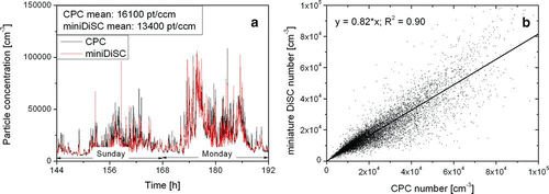
The diurnal variation of the particle number is as expected, with minima during the night and a clearly visible morning rush hour on Monday. The agreement of the two instruments is quite good; the average number concentration differs by 18%. Close to the highway, we expect a large number of ultrafine particles to be present, which could account for the higher particle number concentration measured by the CPC—the TSI model 3775 can measure particles as small as 5 nm, which are not seen by the miniature DiSC.
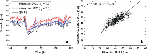
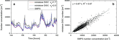
In a second experiment, a miniature DiSC was compared with the home-built UGZ SMPS, which delivers a particle size distribution in the diameter range of 10–320 nm from which the particle number concentration and the geometric mean diameter can be calculated. The SMPS and the miniature DiSC sampled air near a busy road in the city of Zürich. Figures and show the comparison of particle number and geometric mean diameter for a time period of two days. Again, the results are very similar. We note that the calibration of the miniature DiSC for σ g = 1.7 or 2.0 hardly affects the particle number determination, whereas σ g = 2.0 gives a visibly better result for the particle diameter determination. This is not surprising since the average σ g taken from the SMPS over these two days was 2.08. Correlating the diameter values of SMPS and miniature DiSC, we get:
FIG. 12 (a) Comparison of particle number concentration for an SMPS system and a miniature DiSC. The miniature DiSC is calibrated once for σ g = 1.7 and once for σ g = 2.0; the difference in the particle number is hardly visible. (b) Correlation of the case σ g = 2.0 with the SMPS number concentration.
6. DISCUSSION AND CONCLUSIONS
In this article, we have presented a miniaturized version of the DiSC, and some of its applications and limitations. The DiSC is not a precision instrument—by its design, it cannot distinguish between narrow and broad particle size distributions. By calibrating the instrument to a typical width of the expected size distribution, the error that is made is minimized. For emissions from combustion engines, a typical σ g is in the range 1.7–1.8 (CitationHarris and Maricq 2001), while for ambient air with multiple sources σ g is usually larger. We analyzed the entire SMPS data set of 2008 of the station Zürich-Kaserne of the Swiss national air pollution monitoring network (NABEL), consisting of over 50’000 SMPS scans (size range: 10.4–469.8 nm). We found that σ g = 2.11 ± 0.15; 90% of all observed σ g lie in the range 1.85–2.35. We thus conclude that in the future, our instruments should either be calibrated to a “middle ground” (e.g., σ g = 1.9 or 2.0), or specifically for the intended application. While the miniature DiSC is sensitive to the shape of the particle size distribution, we have shown that in theory, the number determination is less sensitive than the diameter determination.
Our new instrument can detect particle concentrations between ∼103– ∼106 pt/ccm. The lower detection limit is given by the electrometer uncertainty of 0.3fA. Using the standard convention that the limit of detection (LOD) is given by 3σ, we need a signal of ∼1fA on the two electrometer stages for a sensible measurement. Usually, the diffusion stage is the limiting stage; it generates 1fA for approximately 103 pt/ccm with a weak dependence on particle diameter. The upper detection limit comes from the maximal detectable electrometer current, which is 4096fA. In the filter stage, this current is generated by ∼106 pt/ccm with a diameter of 100 nm. For larger particles which carry more charge, the upper detection limit is lower and vice versa.
The miniaturized DiSC is a new tool for nanoparticle exposure monitoring. Unlike traditional personal exposure monitoring instruments, it is capable of detecting ultrafine nanoparticles (<100 nm). Like most simple aerosol instruments, it is nonspecific, i.e., specific engineered nanoparticles cannot be distinguished from the ubiquitous background aerosol. While such a distinction can usually only be performed with more complex offline methods, some useful things can be achieved with an unspecific instrument in the workplace, e.g., a warning in case of elevated particle number levels or the localization of a particle source.
Our experimental results correspond fairly well (usually to within 20%) to traditional instruments (SMPS, CPC) in a couple of experiments. Naturally, the miniature DiSC is less accurate than these instruments, but for many applications this is compensated for by its small size. In general, the miniature DiSC should in our opinion be a useful tool in any application where ease of use and portability are more important than high accuracy.
Acknowledgments
We thank Jürg Brunner and Susanne Schlatter of Umwelt- und Gesundheitsamt (UGZ) Stadt Zürich for their cooperation in the field measurements, and for sharing their CPC and SMPS data, and Christoph Hüglin (EMPA) for sharing 1 year of SMPS data of the Swiss NABEL network. We acknowledge funding by the Forschungsfonds Aargau.
REFERENCES
- Aitken , R. J. , Chaudhry , M. Q. , Boxall , A. B. A. and Hull , M. 2006 . Manufacture and Use of Nanomaterials: Current Status in the UK and Global Trends . Occupat. Med. , 56 : 300 – 306 .
- Alonso , M. , Alguacil , F. J. , Santos , J. P. , Jidenko , N. and Borra , J. P. 2007 . Deposition of Ultrafine Aerosol Particles on Wire Screens by Simultaneous Diffusion and Image Force . J. Aerosol Sci. , 38 : 1230 – 1239 .
- Asbach , C. , Fissan , H. , Stahlmecke , B. , Kuhlbusch , T. A. J. and Pui , D. Y. H. 2009 . Conceptual Limitations and Extensions of Lung-Deposited Nanoparticle Surface Area Monitor (NSAM) . J. Nanopart Res , 11 : 101 – 109 .
- Biskos , G. , Reavell , K. and Collings , N. 2005 . Unipolar Diffusion Charging of Aerosol Particles in the Transition Regime . J. Aerosol. Sci. , 36 : 247 – 265 .
- Cheng , Y. S. and Yeh , H. C. 1980 . Theory of a Screen-Type Diffusion Battery . J. Aerosol Sci. , 11 : 313 – 320 .
- Davidson , J. H. and McKinney , P. J. 1998 . Chemical Vapor Deposition in the Corona Discharge of Electrostatic Air Cleaners . Aerosol Sci. Technol. , 29 : 102 – 110 .
- Fierz , M. , Scherrer , L. and Burtscher , H. 2002 . Real-Time Measurement of Aerosol Size Distributions with an Electrical Diffusion Battery . J. Aerosol Sci. , : 1049 – 1060 .
- Fierz , M. , Weimer , S. and Burtscher , H. 2009 . Design and Performance of an Optimized Electrical Diffusion Battery . J. Aerosol Sci. , : 152 – 163 .
- Fierz , M. , Burtscher , H. , Steigmeier , P. and Kasper , M. 2008 . Field Measurement of Particle Size and Number Concentration with the Diffusion Size Classifier (DiSC) . SAE 2008-01-1179 ,
- Fierz , M. , Keller , A. and Burtscher , H. 2009 . Charge-Based Personal Aerosol Samplers . Inhal. Toxicol. , 21 : s130 – 34 .
- Fuchs , N. A. 1963 . On the Stationary Charge Distribution on Aerosol Particles in a Bipolar Ionic Atmosphere . Geofis. Pura Appl. , 56 : 185 – 193 .
- Harris , S. J. and Maricq , M. M. 2001 . Signature Size Distributions for Diesel and Gasoline Engine Exhaust Particulate Matter . Aerosol Sci. Technol. , 32 : 749 – 764 .
- Hoppel , W. A. and Frick , G. M. 1986 . Ion-Aerosol Attachment Coefficients and the Steady-State Charge Distribution on Aerosols in a Bipolar Ion Environment . Aerosol Sci. Technol , 5 : 1 – 21 .
- ICRP (International Commission on Radiological Protection) . 1994 . Human Respiratory Tract Model for Radiological Protection , Oxford, Pergamon : Publication 66. Elsevier Science Ltd. .
- Jung , H. and Kittelson , D. B. 2005 . Characterization of Aerosol Surface Instruments in Transition Regime . Aerosol Sci. Technol. , 39 : 902 – 911 .
- Li , L. , Chen , D. R. , Qi , C. and Kulkarni , P. S. 2009 . A Miniature Disk Electrostatic Aerosol Classifier (Mini-Disk EAC) for Personal Nanoparticle Sizers . J. Aerosol Sci. , 40 : 982 – 992 .
- Lundgren , D. A. and Whitby , K. T. 1965 . Effect of Particle Electrostatic Charge on Filtration by Fibrous Filters . Ind. Eng. Chem. Fundam , 4 : 345 – 349 .
- Marra , J. , Voetz , M. and Kiesling , H. J. 2010 . Monitor for Detecting and Assessing Exposure to Airborne Nanoparticles . J. Nanopart. Res , 12 : 21 – 37 .
- Maynard , A. , Aitken , R. J. , Butz , T. , Colvin , V. , Donaldson , K. , Oberdörster , G. , Philbert , M. A. , Ryan , J. , Seaton , A. , Stone , V. , Tinkel , S. S. , Tran , L. , Walker , N. J. and Warheit , D. B. 2006 . Safe Handling of Nanotechnology . Nature , 444 : 267 – 269 .
- Nel , A. , Xia , T. , Mädler , L. and Li , N. 2006 . Toxic Potential of Materials at the Nanolevel . Science , 311 : 622 – 627 .
- Pui , D. Y. H. , Fruin , S. and McMurry , P. H. 1988 . Unipolar Diffusion Charging of Ultrafine Aerosols . Aerosol Sci. Technol. , 8 : 173 – 187 .
- Ranjan , M. and Dhaniyala , S. 2009 . A Novel Electrical-Mobility-Based Instrument for Total Number Concentration Measurements of Ultrafine Particles . J. Aerosol Sci. , 40 : 439 – 450 .
- Wang , J. , Shin , W. G. , Mertler , M. , Sachweh , B. , Fissan , H. and Pui , D. Y. H. 2010 . Measurement of Nanoparticle Agglomerates by Combined Measurement of Electrical Mobility and Unipolar Charging Properties . Aerosol Sci. Technol. , 44 : 97 – 108 .
- Yoshioka , N. , Emi , H. , Hattori , M. and Tamori , I. 1968 . Effect of Electrostatic Force in the Filtration Efficiency of Aerosols . Kagaku Kogaku , 32 : 815 – 820 .
