Abstract
Two cascade impactors, a Berner Low Pressure Impactor (BLPI model 25/0.018) and a modified BLPI (with a lower pressure drop) were characterized experimentally. First, the critical dimensions of each impactor stage that affect the collection characteristics were measured. Second, the absolute pressures at each stage were determined. Finally, the collection efficiency curves were obtained for all stages in a range of particle sizes from 0.026–13.7 μm. The collection efficiency of the modified impactor was measured using two condensation particle counters (CPC). Monodisperse calibration particles in the submicron size range were generated with a differential mobility analyzer (DMA). A vibrating orifice aerosol generator (VOAG) was used to produce supermicron test particles. In addition, the particle losses of both impactors were experimentally tested using ammonium sulfate particles under dry (15% RH) and wet (>80% RH) conditions. The losses were determined by rinsing a sampling foil and the corresponding impactor stage (nozzle plate, walls and spacer ring) with deionized water. Subsequently, the ammonium sulfate contents of the samples, along with the rinse water, were analyzed using ion chromatography.
Introduction
Impactors have been widely used as sampling devices that provide size selection during particle collection for many years. Marple (Citation2004) recently published a thorough review of impactor history through 1970 and also described the primary subsequent advances in impactor design. The Stokes number (Stk) is a dimensionless impaction parameter that was identified as a basic parameter governing the behavior of particles within impactor jets (Fuchs 1964) and is defined, for a nozzle, as the ratio of the particle stopping distance at the average nozzle exit velocity to the nozzle diameter (Marple and Liu 1974):
Low-pressure impactors use low pressures and high velocities to extend the particle collection range to as low as 20–40 nm. The Berner low-pressure impactor (BLPI) is the most widely used impactor of this type (Berner and Lurzer Citation1980). It is commercially available and has a relatively simple and compact construction. The basic BLPI geometry consists of nozzles set in an annulus, in which the airflow to the following stage passes through a middle part. Manufacturers do not usually calibrate BLPIs, but several calibrations are available for individual stages (Wang and John Citation1988). Several methods have been used to determine the impactor collection efficiency (Marple and Rubow Citation1976; Hillamo and Kauppinen Citation1991; Keskinen et al. Citation1999). The basic design parameters, such as the nozzle diameter (DNozzle), upstream air pressure (Pup), and calibration characteristics of BLPIs, have been measured by Hillamo and Kauppinen (Citation1991).
In this study a new impactor configuration was designed to enable experiments requiring aerosol sampling in high relative humidity. The new design aims to decrease pressure drops and prevent the loss of water content in the retained particles. Losses of secondary organic or inorganic compounds, such as ammonium nitrate, have been attributed to increased pressure drops across the particle-collecting medium (Chang et al. Citation2000). A seven-stage impactor was designed to reduce the pressure drop. A stage 1, with new nozzle dimensions, was added to achieve a lower final cut point. Stages 2–7 existed in the original BLPI. We must emphasize that in Berner type impactors, the numbering of the stages is opposite to at the numbering scheme common to other types of impactors. Therefore, stage 1 refers to the stage with the smallest cut point, while stage 10 of the original BLPI or stage 7 of the modified BLPI refer to the stage with the largest cut point. The retention abilities of the impactors (both the original BLPI and the modified BLPI) were tested by determining the collection efficiency of particles as a function of the particle aerodynamic diameter (Görner et al. 2001). Therefore, the calibration is the first step in the characterization of the original and modified BLPIs.
In the next step, the original and modified BLPIs were tested for particle losses within the impactors in both low and high relative humidity. Even though several experiments have already dealt with impactor losses, only Wang and John (Citation1988) have described Berner impactor losses, and only the average overall losses within certain particle size intervals have been presented. Moreover, some problems with their experiment were later reported (Winklmayr et al. 1990; Jurcik and Wang 1995). In general, experimental studies have shown that the total losses of cascade impactors depend on the particle size and vary from 5–10% (Willeke 1975; Rao 1975; Marple and Willeka 1976; Rubow et al. Citation1987), except in the inlet part, where the losses exceed 30% (Marple et al. Citation1991) in MOUDI. In addition, Vanderpool et al. (1987) and Kwon et al. (Citation2003) tested the loss of liquid particles deposited inside the impactor. The results indicated losses as high as 20%. Because there is no universal theory to determine particle losses, we performed experiments to determine the losses.
The focus of this article is to evaluate the design parameters of the various BLPI stages using new experimental data about the collection characteristics. The same evaluation has been performed for a new configuration (called the modified BLPI). In addition, this study provides the first systematic measurements of the stage-resolved losses of the BLPI type impactor design.
Experimental Setup and Methods
BLPI Calibration
The BLPI 25/0.018 low-pressure impactor used was manufactured by Hauke Gmbh (Austria). Because there is no calibration available for this impactor, it is necessary to determine the parameters describing its collection efficiency. The main calibration task consists of determining Stk50, which is the Stk value for 50% collection efficiency. To properly calculate the Stk value, the stage geometry, impactor flow rate and stage pressure characteristics were determined.
The impactor dimensions relevant to the particle collection characteristics were measured. The nozzle length and jet-to-plate distance were determined with a micrometer screw and a depth gauge. The most critical parameters are the nozzle size and shape, especially in the stages that use compressible flow. The nozzle diameter was measured from both sides of the nozzle plate (stage 1–9) using an optical microscope equipped with a calibrated scale in the eyepiece. The diameter of stage 10 (the stage with the largest cutoff diameter) was estimated using known drill sizes.
The volumetric flow rate through the impactor and the corresponding stage pressures were measured with a laminar flow element (Meriam) and an absolute pressure gauge (Druck). The stage pressures were measured with an original critical orifice 6.40 mm in diameter, producing a volumetric flow rate of 24.58 l/min under standard laboratory conditions (20°C, 101.325 kPa). The stage pressures were measured using a ring with a tap between the stages.
The BLPI calibration comprised several steps with different experimental setups. Stages 1–6 were calibrated using the procedure described in detail by Hillamo and Kauppinen (Citation1991); a short description of the method is given here. Dioctylphthalate (DOP, ρDOP = 983–986 kg/m3) particles were generated using a nebulizer from a solution of DOP in isopropanol. The size distribution of the aerosol from the nebulizer was narrowed using an evaporation/condensation unit. The particles were then classified using a DMA to select only the appropriate part of the original size distribution and limit the influence of doubly charged particles in the resulting monodisperse aerosol. Particles of the desired size were led to the impactor stage, which was operated at the same pressure that it would be in the complete impactor configuration. The particles passed through the impactor jets and were deposited on the impactor plate, which was equipped with a conductive ring under the jet. The charge of the particles deposited on the ring (Qd ) was measured using an electrometer. The particles that passed around the deposition plate were captured in a conductive filter and their charge was measured by another electrometer (Qp ). The stage's collection efficiency (Eff ) for a given particle size was calculated as
The only notable difference was in stage 6, due to differences in construction between our BLPI 25/0.018 and the BLPI 25/0.015 calibrated by Hillamo and Kauppinen (Citation1991) in which not all particles were collected on the narrow conductive ring. Therefore, the ring was broadened using aluminum foil, and stage 6 was calibrated using this broader deposition ring.
In the last four stages (7–10), two methods were used to measure the collection efficiency. The particle generation was the same as in the previous stages, for particles up to 0.7 μm in diameter. Larger particles were produced using a vibrating orifice aerosol generator (VOAG) (TSI, USA) and neutralized using 85Kr neutralizer. The VOAG produces highly monodisperse aerosol particles. The solution of DOP in isopropanol was again used to produce particles ranging in size from 0.5 to 15.0 μm for both measurement methods. Droplets of the desired size are forced in a liquid stream at some volumetric rate through an orifice vibrating at a given frequency (Berglund and Liu 1973). The monodispersity of the produced particles was checked by an aerodynamic particle sizer (APS 3320, TSI).
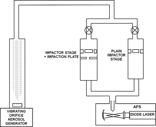
Two methods of particle detection were used to measure the collection efficiencies of stages 7–10 of the BLPI. The first method used the same particle detection technique as stages 1-6, using electrometers to measure the charge carried by the deposited and passed particles. The particles were charged by a corona charger before entering the studied impactor stage. The experimental setup used in this measurement is shown in . Particles within the studied size range carry more than one charge when charged by a corona charger, and the number of charges on a particle is size-dependent. Therefore, the results calculated using Equation (Equation3) are influenced by the differing charges of differently sized particles. Larger particles carry more charges than smaller particles and therefore contribute more to the measured currents in the deposited and passed particle fractions. This effect slightly shifts the measured collection efficiency curve. To check and correct for the possible influence of the size-dependent charge distribution, a second calibration method was used.
FIG. 1 Scheme used to calibrate stages 7–10 of the original BLPI, using charged particles and applying the calibration method of Hillamo and Kauppinen (Citation1991).
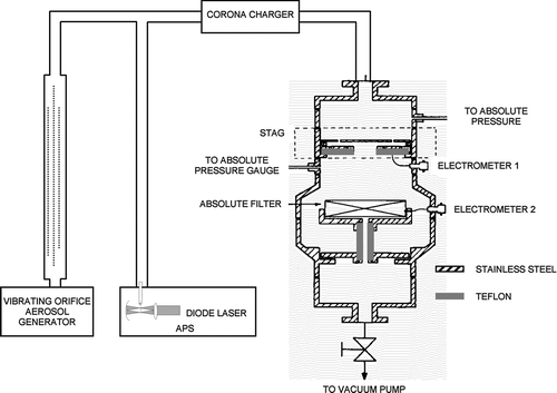
A method that applies APS to detect the number of particles instead of the total charge was used to eliminate the effect described above. At the same time, this second method enables continuous monitoring of particle size and monodispersity and allows only particles of a given size to be considered, thereby eliminating the possible influence of particles with multiple volumes formed by possible coagulation. The method employing APS is further described below.
The setup used in this method is shown in . The particles generated using the VOAG were neutralized by a radioactive source (85Kr). The neutralized particles passed through a stage equipped with an impaction plate and an identical stage without an impaction plate. The number of particles that passed through each stage was recorded by APS. Several cycles were recorded and the average results were used to calculate the collection efficiency. The collection efficiency (E) of particles deposited at an individual stage was calculated as the difference between the number of particles passed through the stages without (Nbp ) and with the impaction plate (Np ), divided by number of particles passed through the stage without the impaction plate (Nbp ).
Design of Modified BLPI with a Backup Filter
The modified BLPI with a low pressure drop was designed to collect aerosol particles at high relative humidity. The design of the modified impactor started from an original 10-stage BLPI (Berner and Lürzer Citation1980). Seven individual stages were set up in a new order to make the impactor output pressure drop smaller than the pressure drop inside the BLPI. The original BLPI stages (stages 2, 1, and 7–10) were arranged to get the pressure behind the last stage to not differ from the atmospheric pressure at the inlet. A new stage 1 (recall that stage 1 is the stage with the smallest cutoff diameter) was designed with a different nozzle diameter and constructed to produce a smaller cutoff diameter for the finest particles. The finest aerosol particles were collected using a quartz fiber filter (QMA Whatman) positioned downstream from stage 1 of the modified impactor. Stage pressures were measured using separate rings with pressure taps placed between stages, the same method used for pressure determination in the original BLPI. The air flow through the modified impactor measured under standard laboratory conditions was 26.0 l/min. The total volumetric flow was regulated by a critical orifice 2.1 mm in diameter placed downstream from the backup filter. The position of critical orifice could theoretically lead to a decreased impactor flow rate due to an increased pressure drop at the backup filter. However, due to low mass loading downstream of the last impactor stage and the relatively high capacity of quartz filters, this situation does not occur under normal atmospheric conditions over 24 h of sampling.
Calibration of Modified BLPI Stage 1–3
The calibration curves and Stk50 values of stages 7, 6, 5, and 4 were taken from the original BLPI calibration described above because these stages are identical to the original BLPI stages 10–7 and work under very similar conditions. The cut diameters (D50) of each stage were calculated using Stk50 values obtained under real conditions inside the modified impactor.
Stages 1–3 of the modified impactor were calibrated in LACP (Laboratory of Aerosol Chemistry and Physics) at a flow rate of 25.0 l/min. The method used was similar in principal to that used for stages 1–6 of the original BLPI; however, the particle detection and particle generation techniques were different.
Two types of generators and solutions were used to produce particles appropriate for the calibration measurements. DEHS (diethylhexylsebacate) particles, 80–400 nm in size, were produced using a nebulizer manufactured at the Institute of Analytical Chemistry of the ASCR (Academy of Science of Czech Republic).
Monodisperse aerosol particles with aerodynamic diameters ranging from 326 nm to 686 nm were generated using a MAG 3000 aerosol generator. A sodium chloride (NaCl) solution with a concentration of 0.5 g/l was used to generate the core particles. The particle cores consisted of sodium chloride crystals and were surrounded by liquid DEHS.
Both types of particles were selected according to size using a DMA, and their aerodynamic diameters da were determined from the measured mobility diameters dp using the following equation:
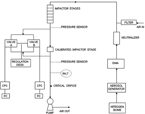
Collection efficiency curves were measured with a system of two CPCs, 3775 and 3022 (TSI) (). One CPC was placed upstream and the other placed downstream of the calibrated stage. In each stage calibration, at least 10 experiments were performed with different particle diameters. Each single experiment with a set particle diameter was repeated four times, interchanging the CPC being sampled (upstream vs. downstream). Switching sampling from the upstream to the downstream CPC was enabled by a regulation desk with 2 valves, called A and B. The collection efficiency was calculated as the geometric mean of the particle number concentrations sampled downstream divided by the geometric mean of the particle number concentrations sampled upstream. To correct errors incurred by operating the CPCs at different pressures, the values obtained downstream of the calibrated stage were multiplied by the pressure ratio (P up /P down ) measured by pressure sensors placed above and below the calibrated impactor stage.
Particle Losses in the Original and Modified BLPIs
Stage resolved particle losses of the original 10-stage BLPI and the modified 7-stage BLPI were determined for the first time for the Berner type impactor. Both impactors sampled ammonium sulfate ((NH4)2SO4) aerosol that was generated using a bubble column aerosol generator filled with ammonium sulfate solution at 100 g/l concentration. The ammonium sulfate aerosol was sampled at low and high relative humidities (RH). Dry conditions were obtained by inserting a diffusion drier downstream of the aerosol generator so that the generated particles dried before being collected at an individual stage. The relative humidity measured at the entrance of the impactor was 15%. High relative humidity was obtained by mixing the generated aerosol with clean air that was humidified using a Nafion diffusion humidifier. The measured relative humidity inside the system was above 80%. In all, 12 experiments were performed. Three experiments were performed for both the original and modified impactors under dry and wet conditions. Greased (Apiezon L 5% solution in toluene) polycarbonate foils (9-μm thick) were used in the dry experiments, and plain foils were used under wet conditions.
The total sulfate (SO2− 4) masses retained on the deposition foils of both the original BLPI and the modified impactor with a backup filter were determined using ion chromatography (IC). After each experiment, the sampling foils and quartz filters were extracted in a mixture of 0.5 ml methanol and 4.5 ml ultrapure water. After 30 minutes in an ultrasonic bath and one hour in an agitator, the samples were filtered using Millipore syringe filters with 0.22-μm porosity and inserted into the IC (200 μl). After each sampling experiment, the ammonium sulfate deposited on the inner surfaces of the impactor was rinsed, stage by stage, with 10 ml of deionized (Ultrapur, Watrex Ltd., conductivity 0.08 μSm−1) ultrapure water and the resulting solution from each rinsed stage was analyzed by IC. The analyses were performed in a setup from Watrex Ltd., with Watrex IC Anion II columns with dimensions 10 μm 150 × 3 mm. The SHODEX CD-5 conductivity detector was used in this setup.
A blank experiment was performed to determine the surface contamination due to impactor operation. The blank result for each impactor stage was obtained from a stage rinse without previous aerosol sampling. The results from the obtained rinse for each impactor stage were averaged, and the mean value obtained in the blanks was deducted from the obtained particle losses for each stage of both the BLPI and the modified BLPI. The percentages of particle losses of each impactor stage were calculated by dividing the SO2 4 (m 2 SO4 rins) losses by the sum of obtained losses and the SO2 4 retained at that individual stage (m 2− SO4).
Results
Original BLPI Impactor Calibration
All results, including the dimensions and retention parameters taken from BLPI calibration, are summarized in
TABLE 1 Basic parameters of the original BLPI25/0.018, measured under standard conditions
The flow rate through the impactor was 24.6 l/min under standard conditions. The upstream and downstream pressures of individual impactor stages were measured using two separate pressure sensors. The obtained values were recalculated to standard conditions (20°C and 101.325 kPa). The final upstream pressures of the given stages are listed in the sixth column of . The downstream pressure of the first stage (7.48 kPa) shows that stage 1 of the BLPI has critical flow and the rest of the stages have compressible flow (stages 2–5) and incompressible flow (stages 6–10).
The collection efficiency of the BLPI25/0.018 has not been experimentally studied before. The S-shaped collection efficiency curves of stages 1–10 are shown in . The collection efficiencies of stages 7–10 measured using both the electrometer and the APS as detectors are shown. The increasing collection efficiencies at the tails of the lowest stages are artifacts from additional collection caused by a force related to the image charge produced by the charged particles (De Juan et al. 1997).
FIG. 4 Collection efficiency of stages 1–10 of the original BLPI using both charged particles and APS.
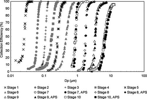
S-curves of Stages 1–10 determining the Stk50 values of each individual stage are presented in .
FIG. 5 Stokes numbers measured for stages 1–10 of the original BLPI using both charged particles and APS.
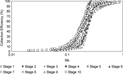
The jet velocity in the adiabatic flow regime was calculated using a method described by Hering (1987). Slip correction factors were calculated using the equation given in Marple and Rubow (1986). The results were used to determine the cutoff D50 and Stk50.
The Stokes numbers at 50% collection efficiency (Stk50) and cut-off diameters (D50) obtained for the individual BLPI25/0.018 impactor stages are presented in the seventh and eighth columns of . Data from both APS and neutral particles were used to determine the Stk50, except in stage 10 in which the average of the two methods was used.
Although a direct comparison of the measured cut points is not possible due to the different design parameters of the impactors, we compared the Stokes numbers at the D50 cut points calculated by Wang and John (Citation1988) with those obtained in our calibration. Whereas our Stk50 values were within the range from 0.19 to 0.24 for all 10 stages, the Stk50 values ranged from 0.18 to 0.28 in their 8-stage impactor. The largest differences were observed in the supermicron stages, in which we found values lower than the theoretical values of 0.24 or 0.22, whereas Wang and John (Citation1988) found values larger than the theoretical values. These differences could result from differences in both the impactor design and in the calibration procedure. Moreover, the small differences in the physical properties used in calculation, uncertainties in the real dimensions of the impactor nozzles and their real shapes may also influence the Stk50 values of the stages. Other authors found similar differences in the Stk50 values. Kwon et al. (Citation2003) found Stk50 values for their K-JIST cascade impactor in a range from 0.18 to 0.28 for D50 values from 0.7 to 10.1 μm; Vanderpool et al. (1990) observed Stk50 values in the range from 0.19 to 0.22 in the atmospheric stages (D50 of 0.50–5.8 μm) and 0.16-0.19 in the low-pressure stages (D50 0.047–0.32 μm). Hillamo and Kauppinen (Citation1991) used the same experimental approach for another BLPI model to find Stk50 values ranging from 0.20 to 0.22 in submicron stages. Marjamäki et al. (2000) obtained Stk50 values ranging from 0.18 to 0.23 in the submicron stages and 0.20 to 0.23 in the supermicron stages in calibration of an ELPI impactor. Generally, our results are in good agreement with those of other authors.
Modified BLPI
The calibration results, design parameters and collection parameters of the modified impactor are listed in . The presented results were recalibrated to standard conditions.
TABLE 2 Basic parameters of the 7-stage modified BLPI, measured under standard condition
The modified BLPI consists of seven stages; six stages originated in the 10-stage BLPI, and stage 1 is new. The nozzle diameters of stages 2–7 were taken from the original BLPI calibration. The nozzle diameter of stage 1 was measured separately using the same microscopy technique. Therefore, the tolerance of the measurement remains the same as it was for the original BLPI. Stage 1 contains 65 cylindrical nozzles, 0.29 mm in diameter. The number of nozzles, their diameters, jet-to plate distances and Reynolds numbers at each stage are summarized in .
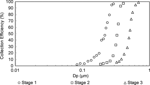
The stages were arranged to produce a reduced pressure drop through the impactor to prevent the sampled aerosol particles from losing their water content. The resulting upstream pressures of stages 1–7 are shown in the sixth column of . The measured pressures show that the pressure drop over the modified BLPI is much lower than that of the original BLPI. The low number of stages, along with the high upstream pressure, leads to a reduced separation efficiency for ultrafine particles. The first three stages were modified and rearranged to collect particles smaller than 1 μm. The efficiencies of stages 1–3 thus were determined, and the resulting collection efficiency curves are shown in . The new stage 1 has a cutoff diameter of 0.207 μm. Therefore, a backup filter was placed behind the last impactor stage to gather the finest aerosol particles. The aerodynamic particle diameters at 50% collection efficiency (D50) of each stage are shown in .
The resulting S-shaped efficiency curves (E) were calculated from the penetration efficiencies by using the Least-Squares Method to fit the experimental data:
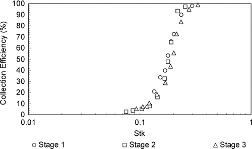
Curves of the efficiency versus the Stokes number of stages 1–3 are shown in . The Stk50 values of stages 1–3 were determined from the efficiency curves; the Stk50 values of stages 1, 2, and 3 were 0.20, 0.23, and 0.19, respectively, in good agreement with the theoretical Stk50 of 0.24 for a circular orifice (John 1999) and with the ranges of Stk50 measured by other authors as mentioned above. The rest of the individual stage Stk50 values, taken from the original BLPI, are listed in . Stage 3 of the modified impactor has dimensions identical to those of stage 1 of the original BLPI. Therefore, their measured Stk50 values should be approximately the same if the Stokes number correctly describes the process of particle impaction on the stage. Good agreement in Stk50 was obtained even though the upstream pressures of each impactor stage were quite different. The Stk50 values of the compared stages differed by only 0.007. Similarly, stage 2 of the modified impactor was compared to stage 2 of the original BLPI. The difference in their Stk50 values was 0.019, which is still considered a good result. The similarity in the obtained Stk50 values of identical impactor stages confirms that the calibration experiments were performed carefully and with high accuracy despite the different calibration approaches.
Due to the influence of the particle density on the Stokes number, the proper density for calibration of stage 3 had to be computed. The density of the particles used in calibration of stage 1 and 2 did not need to be estimated because the particles originated from DEHS in isopropanol solution. The aerosol particles used to calibrate stage 3 were generated by a MAG aerosol generator, which produces particles consisting of a sodium chloride core with a mobility diameter of 74 nm surrounded by DEHS. The particle density ρ p at a certain particle diameter dp was calculated for each given size:
Particle Losses
Particle losses in both the original and modified BLPIs were measured. The distance ring, jet plate, and impaction plate support (not the deposition foil with particle deposits) were rinsed together, and the losses were presented as the sum of particle losses obtained at each stage. This means that particles deposited on the upper side of the nozzle plate were attributed to the stage downstream. Although this attribution is a problematic issue, we could not separate the particles deposited on the bottom side of the nozzle plate from those deposited on the upper side and thus had to assign the particles deposited on both sides of the nozzle plate to a stage. The reasons for our decision are presented.
First, we observed halo-like deposition patterns around the nozzles at the bottom side of the nozzle plate. These were different halo patterns from those regularly observed around deposition spots on deposition foils (mainly in the high-velocity stages with fewer nozzles), and we did not observe any particles on the upper side of the nozzle plate.
Second, much more deposition of fine particles can be expected on the bottom side of a nozzle plate due to the much higher turbulence levels below the nozzles compared to the space above the nozzles produced by the high jet velocities. Therefore, attributing the complete rinse of a nozzle plate to downstream losses probably does not cause large errors in determining the stage losses, at least for submicron stages.
In the case of coarse particles, some deposition on the upper side of the nozzle plate can be expected; however, the size distribution of the aerosol employed suppressed this effect in the measured losses, because the mass of the dry aerosol at stage 10 was lower than that at stage 9, and so on until stage 6. Nevertheless, some effect can be expected for coarse particles, with the influence increasing with the size of the particles.
The data were corrected to account for the deposition foil blanks and the stage rinse blanks. Separate greased (0.014 ± 0.005 μg/m3) and plain foil (0.017 ± 0.004 μg/m3) blanks were used. The stage rinse blank (0.062 ± 0.031 μg/m3) was computed from the average of the blank rinse experiments for an individual stage. All of the concentrations were corrected to blanks that correspond to low concentrations measured at stages 1 and 2 of the BLPI. Because the detection limit of ammonium sulfate is about 0.01 ppm, and the aforementioned concentrations of the original stage 1 and stage 2 were near this value, we decided to exclude those data from the results.
Particle losses, expressed as percentages, are shown in for the original BLPI and in for the modified BLPI. Two basic features were observed. The 7-stage modified impactor exhibits lower total losses than the original BLPI. Impactor losses are presented for stages 3–9 of the original BLPI and stages 1–6 of the modified BLPI. Stage 10 of the original BLPI and stage 7 of the modified BLPI were not included because it was impossible to separate those stages from the pre-impactor and they were thus rinsed together. Therefore, it was not possible to determine the losses of those stages.
FIG. 8 Original BLPI particle losses measured under dry conditions (15% RH) and wet conditions (>80% RH).
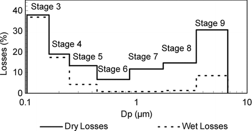
FIG. 9 Modified BLPI particle losses measured under dry conditions (15% RH) and wet conditions (>80% RH).
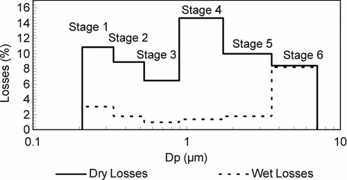
The relative particle losses of the individual impactor stages and their standard deviations are listed in . The original and modified BLPI stages with the same impacted particle size intervals are listed in the same row. The losses observed for the two impactors in the stages containing coarse particles (∼1–10 μm) are comparable, which was expected due to their identical constructions and small differences in flow rates, except for the results observed in stage 9 of the original BLPI and stage 6 of the modified BLPI under dry conditions. However, the results for those stages under dry conditions are prone to larger errors than the other stages due to the low concentrations measured during the experiments and the uncertainties in the blank rinses. Experimental tests have shown that the losses obtained for the coarse dry particles vary from 11.8% to 32.5% in the original BLPI (stages 7–9) and from 8.4% to 14.4% in the modified BLPI (stages 4–6). The same experiment using wet particles exhibits much lower losses in the coarse mode (0.7–8.6% for the original BLPI and 1.3–8.2% for the modified BLPI). In contrast, Vanderpool et al. (1987) and Marple at al. (Citation1991) reported that the inter-stage losses of large liquid particles were generally twice as high as those of solid particles.
TABLE 3 Averages and standard deviations of particle losses in each stage of the original and modified BLPIs obtained under dry and wet conditions
Lower particle losses were found for fine wet particles (∼0.1–1 μm) in both the original BLPI (stages 3–6) (6.6–37.7% under dry and 0.9–36.8% under wet conditions) and the modified BLPI (stages 1–3) (6.4–10.8% under dry and 1.0–3.1% under wet conditions). The lowest losses were found for particles in the accumulation mode. Solid particle capture is a strong function of the impaction surface used. Better retention is obtained for stickier surfaces (Marple and Willeke 1976). Nevertheless, we suppose that most of the losses were the result of particles bouncing or disintegrating inside the impactor. The difference between our results and those of Vanderpool et al. (1987), Marple et al. (Citation1991), and the paper by Pak et al. (1992), may indicate that the greasing procedure used here may be insufficient when a completely dry, hard aerosol is sampled.
The highest particle losses were found for particles collected on stage 3 of the original BLPI under dry conditions. We suppose that most of the losses were caused by the dry particles bouncing despite the grease coating on the impaction foils. Another loss mechanism could be related to turbulent diffusion of particles within the inner circulation of aerosol between the nozzle plate and the impaction plate after the jet strikes the impaction foil. “Halo” patterns of deposited ammonium sulfates were visible around the bottom part of the nozzles after the experiments. Both bounced particles and smaller particles might be retained due to the centrifugal forces caused by the gas vortex.
Stage 4 of the original BLPI retains particles in a similar size interval as stage 1 of the modified BLPI. Nevertheless, the losses of the original BLPI were higher than those of the modified BLPI, in both dry and wet cases. This loss is probably caused by the higher jet velocity and lower pressure in the original BLPI. The higher velocity probably causes greater rebound, and both the higher velocity and lower pressure contribute to stronger turbulent diffusion losses. For the wet particles, the lower pressure leads to lower relative humidity and may cause them to dry on the deposition foil surface or even before deposition. The drying might occur in the deposited fraction, for which a solid surface is available to initiate nucleation. Dried particles might be blown off of the deposition foil by the high-velocity jet. Wet particle drying is not probable prior to deposition in stage 4 of the original BLPI, because the upper and lower stage pressures on this stage are not low enough to produce a relative humidity below the ammonium sulfate efflorescence point. However, the aforementioned hypothesis probably explains the losses obtained in stage 3 of the original BLPI with high RH. Because the upstream pressure at BLPI Stage 3 is 47.34 kPa, the estimated upstream RH at this stage was 37.5% and the downstream RH was 24.9% (downstream pressure of 29.9 kPa). The ammonium sulfate particles used have an efflorescence point at 35% RH (Seinfeld and Pandis 1998), which is slightly lower than the upstream RH and higher than the downstream RH. Therefore, the particles may dry and behave as dry particles. Another possible mechanism involves suspended particles being stressed by the external forces connected with jet hydrodynamics (Roeber Citation1957). Generally, drying is often visible during sampling in a humid environment in the BLPI, when so-called satellite droplets in the deposits can be found on stages 5 and 6 but not on the lower stages.
We suppose that the fine atmospheric particles usually contain many organic substances that can often be in a liquid or semi-liquid state. Therefore, we suppose that real atmospheric particle losses will be similar to the wet case. Coarse particle losses will be much more dependent on the ambient humidity and properties of the impaction material.
The losses obtained for both impactors were not included in the calibration measurements because the losses were measured using aerosol with a broad bimodal size distribution in the whole impactor at the same time as opposed to measuring the losses at individual sizes. Therefore, the losses for exact particle diameters could not be determined. On the other hand, only the loss of wet particles could be taken into account, because the calibration experiments were performed using liquid particles.
The particle losses obtained for the original and modified BLPIs are comparable with experiments performed by Willeke (1975), Rao (1975), and Rubow et al. (Citation1987), except for the results regarding coarse particles retained inside the BLPI under dry conditions. In general, the results for both impactors at different RHs confirm the universal opinion that almost 10% of the retained mass is lost during the collection process inside impactors. In our case, the losses were measured for the whole impactor, in contrast to, e.g., Marple et al. (Citation1991), who measured losses in single stages.
Wang and John (Citation1988) studied the losses inside another type of BLPI. They used monodisperse aerosol to quantify particle losses in individual impactor stages. However, they only reported the average loss of the impactor for particles in the larger size ranges. They reported 1.1% losses for particles larger than 2 μm and 3% for sizes ranging from 0.5–2 μm. The reduced particle losses for particles in the supermicron range were the opposite of what we observed in our loss measurements.
Better qualitative agreement was obtained for fine particles, for which they reported an average loss of 8.1% for particles from 0.056 to 0.43 μm but only 5% for particles larger than 0.2 μm. These results imply increased losses of fine particles, in agreement with our stage-resolved losses, which increased as the stage cut diameter decreased.
The measured dry losses attributed to larger particles that rebounded through the impactor might influence both the deposited and lost fractions of the lower stages. The described experiments are closer to real sampling situations, in which complex aerosols are sampled by the entire impactor and are subject to all non-idealities of the real world.
Conclusions
The Berner Low Pressure Impactor (BLPI 25/0.018) and the 7-stage modified BLPI were calibrated separately. The modified impactor was designed for wet aerosol sampling. The impactor nozzle diameters were determined; all studied nozzles (stages 1–9) were cylindrically shaped with deviations in diameter varying from 0.8 to 1.5% in any individual stage.
The upstream pressures of each stage were measured. In the original BLPI, the upstream pressure drops from atmospheric pressure to 17.74 kPa from stage 10 to stage 1. The modified impactor consists of 6 of the original BLPI stages and one new stage. The new design reduces the total pressure drop; the pressure measured at stage 1, the finest stage, was 96.21 kPa.
The Stk50 and D50 values of individual impactor stages were determined from the calibration experiments. The obtained Stokes numbers at 50% collection efficiency for all calibrated stages of both impactors were within the interval 0.18 to 0.24. The calculated D50 values set the BLPI collection range from 0.026 μm to 13.70 μm, whereas the smallest cut diameter of the modified BLPI is 0.21 μm. For this reason, a backup filter was placed behind the last stage of the modified BLPI to collect the finest aerosol particles.
The particle losses of both impactors were tested using ammonium sulfate aerosol particles at 15% RH and over 80% RH. In general, the modified BLPI exhibits lower particles losses than the original BLPI. The losses observed in the size interval from 0.1 to 10 μm under wet conditions (0.7-36.8% for the original BLPI and 1.0–8.2% for the modified BLPI) were lower than the losses measured under dry conditions (6.6–37.7% for the original BLPI, 6.4–14.7% for the modified BLPI).
Acknowledgments
This work was supported by a grant from the Ministry of Education. Youth and Sports CR. Program COST. No. OC 106 and Program KONTAKT - ME 941. The work was also supported by grant No. 205/09/2055 of GA CR.
REFERENCES
- Berglund , R. N. and Liu , B. Y. H. 1973 . Generation of Monodisperse Aerosol Standards . Environ. Sci. Technol. , 7 : 147 – 153 .
- Berner , A. and Lurzer , C. 1980 . Mass Size Distributions of Traffic Aerosols at Vienna . J. Phys. Chem. , 84 : 2079 – 2083 .
- Chang , M. M. , Siotas , C. , Kim , S. , Gong , H. Jr. and Linn , W. 2000 . Reduction of Nitrate Losses from Filter and Impactor Samplers by Means of Concentration Enrichment . Atmos. Environ. , 34 : 85 – 98 .
- De Juan , L. , Brown , S. , Serageldin , K. , Davis , N. , Rosell , J. , Lazcano , J. , De Fernández , La and Mora , J . 1997 . Electrostatic Effects in Inertial Impactors . J. Aerosol Sci. , 28 ( 6 ) : 1029 – 1048 .
- Fuchs , N. A. 1964 . The Mechanics of Aerosols. , 139 New York : Pergamon Press .
- Görner , P. , Wrobel , R. , Mička , V. , Škoda , V. , Denis , J. and Fabries , J. 2001 . Study of Fifteen Respirable Aerosol Samplers Used in Occupational Hygiene . Ann. Occup. Hyg. , 45 ( 1 ) : 43 – 54 .
- Hering , S. V. 1987 . Calibration of the QCM Impactor for Stratospheric Sampling . Aerosol Sci. Technol. , 7 ( 3 ) : 257 – 274 .
- Hillamo , R. E. and Kauppinen , E. I. 1991 . On the Performance of the Berner Low Pressure Impactor . Aerosol Sci. Technol. , 14 : 33 – 47 .
- Hinds , W. C. 1999 . Aerosol Technology: Properties, Behavior, and Measurements of Airborne Particles. , 54 New York : John Wiley & Sons .
- John , W. 1999 . A Simple Derivation of the Cutpoint of an Impactor . J. Aerosol Sci. , 30 ( 10 ) : 1317 – 1320 .
- Jurcik , B. and Wang , H.-C. 1995 . On the Shape of Impactor Efficiency Curves . J. Aerosol Sci. , 26 ( 7 ) : 1139 – 1147 .
- Keskinen , J. , Marjamäki , M. , Virtanen , A. , Mäkelä , T. and Hillamo , R. 1999 . Electrical Calibration Method for Cascade Impactors . J. Aerosol Sci. , 30 : 111 – 116 .
- Kwon , S. B. , Lim , K. S. , Jung , J. S. , Bae , G. N. and Lee , K. W. 2003 . Design and Calibration of a 5-Stage Cascade Impactor (K-JIST cascade impactor) . J. Aerosol Sci. , 34 : 289 – 300 .
- Marjamäki , M. , Keskinen , J. , Chen , D.-R. and Pui , D. Y. H. 2000 . Performance Evaluation of the Electrical Low-Pressure Impactor (ELPI) . J. Aerosol Sci. , 31 ( 2 ) : 249 – 261 .
- Marple , V. A. and Liu , B. Y. H. 1974 . Characteristics of Laminar Jet Impactors . Environ. Sci. Technol. , 8 ( 7 ) : 648 – 654 .
- Marple , V. A. 2004 . History of Impactors—The First 110 Years . Aerosol Sci. Technol. , 38 : 247 – 292 .
- Marple , V. A. and Rubow , K. L. 1976 . Aerodynamic Particle Size Calibration of Optical Particle Counters . J. Aerosol Sci. , 7 : 425 – 433 .
- Marple , V. A. and Willeke , K. 1976 . Impactor Design . Atmos. Environ. , 10 ( 99 ) : 891 – 896 .
- Marple , V. A. and Rubow , K. L. 1986 . Cascade Impactor, Sampling, & Data Analysis . Akron: Am. Hyg. Assoc. , : 79 – 101 .
- Marple , V. A. , Rubow , K. L. and Behm , S. M. 1991 . An Microorifice Uniform Deposit Impactor (MOUDI): Description, Calibration, and Use . Aerosol Sci. Technol. , 14 : 434 – 446 .
- May , K. R. 1975 . Aerosol Impaction Jets . J. Aerosol Sci. , 6 : 403 – 411 .
- Pak , S. S. , Liu , B. Y. H. and Rubow , K. L. 1992 . Effect of Coating Thickness on Particle Bounce in Inertial Impactors. . Aerosol Sci. Technol. , 16 : 141 – 150 .
- Rao , A. K. 1975 . An Experimental Study of Inertial Impactors. Ph.D. Thesis , Particle Technology Laboratory. Mech. Eng. Dept., University of Minnesota .
- Roeber , R. 1957 . Untersuchungen zur konimetrischen Staubmessung . Staub. Heft , 49 : 273 – 296 .
- Rubow , K. L. , Marple , V. A. , Olin , J. and McCawley , M. A. 1987 . A Personal Cascade Impactor: Design, Evaluation, and Calibration . Am. Ind. Hyg. Assoc. J. , 48 : 532 – 538 .
- Seinfeld , J. H. and Pandis , S. N. 1998 . Atmospheric Chemistry and Physics. , 450 New York : John Wiley & Sons .
- Vanderpool , R. V. , Lundgren , D. A. , Marple , V. A. and Rubow , K. L. 1987 . Cocalibration of Four Large-Particle Impactors . Aerosol Sci. Technol. , 7 : 177 – 185 .
- Vanderpool , R. W. , Lundgren , D. A. and Kerch , P. E. 1990 . Design and Calibration of an In-Stack Low-Pressure Impactor . Aerosol Sci. Technol. , 12 ( 2 ) : 215 – 224 .
- Wang , H. C. and John , W. 1988 . Characteristics of the Berner Impactor for Sampling Inorganic Ions . Aerosol Sci. Technol. , 8 : 157 – 172 .
- Willeke , K. 1975 . Performance of the Slotted Impactor . Am. Ind. Hyg. Assoc. , 36 ( 9 ) : 683 – 691 .
- Winklmayr , W. , Hwa-Chi , W. and John , W. 1990 . Adaptation of the Twomey Algorithm to the Inversion of Cascade Impactor Data . Aerosol Sci. Technol. , 13 ( 3 ) : 322 – 331 .
