Abstract
Black carbon emitted from vehicles or industrial plants is a very common phenomenon observed by high school students. A cost effective and user friendly measurement protocol will greatly enhance school students’ capability to investigate the black carbon pollutant in their ambient environments, and hence their awareness to environmental protection. This study shows the potential of applying digital imaging as an alternative method to measure airborne elemental carbon (EC). Aerosols were collected on filters and the blackness of the filters was digitalized into RGB values using an office scanner. It was found that maximum value of transformed R, G and B values (255 – R, 255 – G and 255 – B, respectively), max {R’,G’,B’}, was power-law related with the EC loading of the filter (R2 = 0.85, n = 55). The power-law relationship between the max{R’,G’,B’} and EC loading could be applied as a cost effective and user friendly method to quantify EC by high school students. Using this method, the sampling flowrate and duration should be controlled so that the max{R’,G’,B’} of the filter samples lie in the optimal range between 40 and 170 to minimize the uncertainty. For samples within this range, the average percentage difference between the results of this method and the results from conventional thermal-optical method was found to be only 10.3%, which is close to common research grade instruments.
INTRODUCTION
Airborne elemental carbon (EC) plays an important role in various atmospheric processes and chemistries. It is a particulate pollutant species emitted from the combustion of carbonaceous fuel. It absorbs light due to the mobility of electrons in its six-member ring structure, and leads to extinction of radiation. It also plays an important role in global warming. It was suggested that EC may be the second most important component of global warming after carbon dioxide in terms of direct forcing (CitationJacobson 2001). High porosity also enables EC to adsorb/absorb other pollutants and becomes cloud condensation nuclei (CitationLammel and Novakov 1995). Due to the above environmental impacts, it is important to quantify its atmospheric concentrations, which had been reported by numerous studies (CitationOffenberg and Baker 2000; CitationLin and Tai 2001; CitationKendall et al. 2002; CitationViidanoja et al. 2002; CitationChow et al. 2005; CitationCao et al. 2007). In general, its concentrations range from 0.2–2.0 μg/m3 in rural and remote areas to 1.5−20 μg/m3 in urban areas (CitationSeinfeld and Pandis 1998).
EC is sometimes termed as “black carbon” (BC), due to its light absorption property. However, they are not exactly the same, as they are operationally defined by different measurement method applied. BC is defined as the strongly light absorbing fraction in the air that is quantified by optical method. The amount of light absorbed and the extent of blackness of filter increases with the amount of BC. Instruments such as aethalometer, multi-angle absorption photometer and light transmission photometer are commercially available for BC measurement.
On the other hand, EC is defined by its thermal and chemical properties. It is insoluble in polar and non-polar solvents and resistant to oxidation at temperature under 400°C (CitationPenner and Novakov 1996). Atmospheric organic carbon (OC) and EC are determined by combusting filter samples with sequential ascending temperature and quantification of OC and EC are achieved by measurement of the evolved carbon dioxide at different temperatures (CitationCachier et al. 1989; CitationLin and Tai 2001). In some studies, the reflectance or transmittance of the filters were monitored to correct the charring of OC during combustion at lower temperature (CitationBirch and Cary 1996; CitationViidanoja et al. 2002; CitationChow et al. 2005). Although EC and BC are defined differently, some studies had shown that EC and BC were comparable (CitationAllen et al. 1999; CitationHitzenberger et al. 2006) since EC is the principal light absorbing component in ambient air (CitationRosen et al. 1978; CitationGundel et al. 1984; CitationHorvath 1993). Hence, EC and BC are often used interchangeably.
While the aforementioned instruments provide accurate measurement for scientific research on EC or BC; their high cost restrains the learning of atmospheric science for high school students. Black carbon emitted from vehicles such as heavy duty trucks or industrial chimneys is commonly observed phenomenon to high school students. A user friendly and cost effective measurement means for EC will definitely facilitate scientific investigations by high school students. Based on the light-absorbing property, a digital imaging approach incorporated with RGB color model is proposed in this study to quantify the elemental carbon in the air. Digital imaging had been applied in various environmental studies, for example, CitationBaümer et al. (2008) used digital imaging with an edge detection algorithm to determinate visibility; while CitationDoi and Ranamukhaarachchi (2007) digitalized soil color to monitor the rehabilitative effects by Acacia auriculiformis on degraded land as soil minerals have different colors. However, digital imaging has not been applied to study the concentrations of airborne elemental carbon. RGB system is the most commonly employed color model in computer technology. It is an additive color model in which red (R), green (G), and blue (B) lights are added together with various intensities to produce a broad array of colors. If digital imaging can be applied in measuring EC in the air, it would greatly promote teaching and learning of atmospheric science in high schools as equipment (scanner) required is readily available and affordable. Students’ awareness in environmental protection would also be enhanced through their own experience in measuring air quality.
In this study, blackness of filters have been digitalized by an office scanner and compared with the amount of EC quantified by thermal-optical method to investigate the feasibility of deploying digital imaging approach to quantify airborne elemental carbon.
EXPERIMENTAL APPROACH
Air Sampling
Atmospheric aerosol samples were collected on the roof of a residential building in Hong Kong and Guangzhou, China with a high volume sampler (Graseby, GMWT 2200). The sampler was equipped with an impactor with a cut-off aerodynamic diameter at 2.5 μm (Graseby, Model 231-F) and was operated at a flowrate of 40 ft3/min. Quartz filters which had been thermally pretreated at 500°C for 5 h to remove residue organics were used. In order to collect a wide range of quantity of elemental carbon, the duration of sampling ranged from 0.5 to 24 h. A total of 79 filter samples were collected, of which 70% (55 samples) was randomly selected to build a mathematical model relating the digitalized color to EC loading, whereas the remaining 30% (24 samples) of the collected samples were used to test the model built (CitationTan et al. 2006).
Quantification of EC
The filter samples were analyzed for OC and EC using a Thermal/Optical Carbon Analyzer (CitationSunset Laboratory Inc. 1996) following IMPROVE thermal-optical transmittance (TOT) protocol (CitationChow and Watson 2002). Punches of samples (1 cm × 1 cm) were heated stepwise at temperatures of 120°C, 250°C, 450°C, and 550°C in pure helium atmosphere, and 550°C, 700°C, and 800°C in 2% oxygen and 98% helium atmosphere. The carbon that evolved at each temperature was oxidized to carbon dioxide, and then reduced to methane for quantification with a flame ionization detector. Transmittance of each filter sample was monitored during the process and OC/EC split was set when the transmittance returned to its initial value. The carbon evolved prior to the split was considered as OC and the carbon evolved after the split was considered as EC. The amounts of carbon collected were reported as μg/cm2.
Digital Imaging
An office scanner (Canon, PIXMA MP150) was used to capture the image of each filter. The images were saved in JPEG format with 300 pixels per inch and a graphic editing program, Adobe Photoshop CS3 was used to analyze the color of the images. Photoshop read the values of the filter colors in RGB color system. For each sample, an area of 0.9 cm × 0.9 cm (110 × 110 pixels) was sampled and the average value of RGB, as well as the individual values of red, green, and blue, were recorded. In order to understand the light absorption property of pure EC, color of activated carbon pellets (Sigma-Aldrich) was also recorded to serve as a reference EC color. The activated carbon was added on the surface of a filter after grinded and the color of filter was digitalized as air samples.
RESULTS AND DISCUSSIONS
Carbon Loadings
A total of 79 samples, were collected by the high volume sampler. The EC loadings ranged from 0.001 to 22.12 μg/cm2, with an average of 5.01 μg/cm2. OC loadings in the samples were also measured and it was found that the OC/EC ratio in those samples ranged from 1.7 to 22.8, with an average of 6.5.
Color Profile of Blank Filter and Activated Carbon
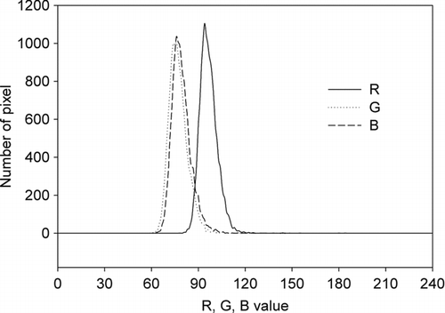
Color of a blank filter was scanned and it was found that the filter was highly reflective and its average RGB value was 253.9 with the average R, G, and B values of 253.6, 254.0, and 254.1 respectively. Five filters with different amounts of activated carbon were also scanned. The color profile of the reflected light from activated carbon showed that the intensity of red light was higher than that of green or blue (). Non-uniformity of light intensity, sensitivity of scanner, and reflectivity of filter with different wavelengths can result in larger R values than G and B values, however measurement of the light spectrum of the scanner light showed that red was not the highest intensity of lights emitted by the scanner (data not shown). In addition, the average R, G, and B values of a blank filter showed the larger R values of activated carbon was not due to the effect of sensitivity of the scanner or the reflectivity of the filter. Therefore, it is suggested that although activated carbon absorbs visible lights of all wavelengths, it absorbs less light with longer wavelength (red).
Digitalized Color of Filter Samples
In Photoshop, the intensities of red, green, and blue lights are specified with three 8-bit unsigned numbers (0 through 255, 255 is the highest intensity). RGB value is the average of these three numbers. RGB value of 0 indicates black while 255 indicates white. Hence, in this study, the RGB value was transformed into RGB’ value by subtracting from 255 (i.e., RGB’ = 255 – RGB) to establish a positive relationship between the digitalized color values and EC concentrations.
The homogeneity of particulates collected on filters was firstly tested. Two portions (0.9 cm × 0.9 cm each) of 13 samples were cut from the edge and the center of each filter and scanned. Paired t-test showed that there were no significant difference between the edge portions and center portions in RGB’ values (p-value = 0.68, two tails). Therefore, the digitalized color of a filter sample should not vary with position. In other words, EC collected was evenly distributed on the filter surface.
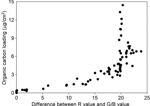
The RGB' values of field samples ranged from 1.5 to 205.8. From the color profiles, it was found that in most scanned samples, red color showed the highest intensity, followed by green color. It is similar to the color profile of activated carbon as mentioned above. Hence, the difference in the color intensities of field samples may due to the light absorption nature of EC as illustrated by activated carbon. The presence of light-absorbing or colored organic compounds, such as humic like substances (HULIS), can also lead to the discrepancy in color intensities (CitationGelencsér et al. 2003; CitationHegglin et al. 2002), although the absorption coefficients of most OC are small when compared with EC (CitationHorvath 1993). shows that the difference between red intensity and green/blue intensity increased with the increase of OC loading. Atmospheric aerosols are complexly composed. Since different compounds possess different light absorption and physical properties, establishing a relationship between the OC loading and the color intensities without knowing OC compositions is difficult and is beyond the scope of this study.
In addition, the presence of colored metals in the ambient aerosols was likely responsible for the higher intensity of red/brown color. It is supported by CitationUrszula et al. (2001) who had found that the brown/red color on filter is associated with aluminum, iron and scandium. These metals are common in the atmospheric air in Hong Kong and other regions. In Hong Kong, the average atmospheric concentrations of aluminum and iron range from about 120 to 2500 ng/m3 and about 200 to 1500 ng/m3 (Ho et al. 2006; CitationLee et al. 2007), respectively. The average atmospheric concentration of scandium in the rural area of Hong Kong is about 0.12 ng/m3 (CitationLam et al. 2004). Moreover, in this study, after analyzing the EC loading with the thermal-optical carbon analyzer, the color of some combusted filters (n = 14) were digitalized into RGB values. It was found that the red intensities of those combusted samples were higher than those of green and blue intensities (). The red color of combusted filter was not caused by EC as all EC should be oxidized during the thermal optical analysis. This is supported by the close agreement among the average values of R, G, and B measured on the combusted filter with activated carbon, which was 252.3, 252.2, and 251.7, respectively. The red color of combusted filter can therefore be due to some metals that may present on the filter and cannot be oxidized during the combustion. Fe2O3 can be one of the examples. It can be formed in the second stage of the thermal-optical analysis (at high temperature and in the presence of oxygen) and it decomposes at temperature above 1566°C.
TABLE 1 The red (R), green (G), and blue (B) values of combusted field samples and their differences
Relationship between Digitalized Color and EC Loading
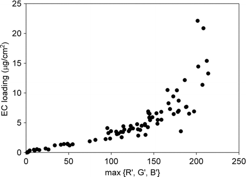
The more EC collected on the filter, the more light is absorbed during scanning and hence less light is received by the sensor of the scanner. Therefore, the amount of the EC on a filter is in negative relationship with the light reflected back. With the digital imaging approach proposed in this study, the reflected light is expressed as RGB values. The comparative higher R value in the activated carbon and filter samples which may not be related the EC as discussed above will lead to a higher overall RGB value. To avoid underestimation of the EC loading with the digital imaging approach in this study, the minimum value of red, green and blue intensities of each scanned filter was adopted to establish a relationship between the digitalized colors and EC loadings. Minimum value of R, G, and B equals to the maximum value of transformed R, G, and B, (max{R’,G’,B’}, where R’ = 255 – R; G’ = 255 – G; B’ = 255 – B). shows the EC loadings on filters with different maximum values of R’, G’ and B’. It shows that, when the max{R’,G’,B’} was low, a good linear relationship was found between the max{R’,G’,B’} and the EC loading. However, for the max{R’,G’,B’} larger than 150, the relationship was not linear. It was due to the fact that RGB is not a linear function of color intensity. Although RGB is a device-dependent color space, (which means different electro-optical devices detect or reproduce a given RGB value differently), most devices do not convert the optical signal into electric signal proportionally. Instead, gamma correction is used to encode optical signal into electric signal (CitationHardeberg 2001) and it is defined as:
FIG. 3 Elemental carbon (EC) loadings on filters with different maximum value of transformed R, G, and B (max{R’,G’,B’}).
-
O represents optical signal
-
e represents electric signal
-
k and γ are real numbers and vary with different devices
Therefore, the digitalized color does not linearly relate with light intensity or EC loading.
In this study, the optical signal O was the reflected light from the scanned filter, which was related to the EC loading, [EC], and the electric signal e was represented by max{R’,G’,B’}. Hence EquationEquation (1) could be rewritten as [EC] = k (max{R’,G’,B’}) γ. Taking logarithm on both sides, the equation became log [EC] = γ log (max{R’,G’,B’}) + log k. In order to test if the digitalized color was power-law related with the EC loading as gamma correction and to build a model for EC estimation, linear regression analysis was conducted for log [EC] and log (max{R’,G’,B’}) with 70% of collected samples (i.e., 55 samples). The rest of the samples (i.e., 24 samples) were used for verification.
High linearity (R2 = 0.85) was found between log [EC] and log (max{R’,G’,B’}) as shown in . The 95% confidence interval of the regressed line was also estimated for its uncertainty. Accordingly, the log-log regression plot appears to be a very good fitted model with low uncertainty. With the regression coefficients, the following model was suggested for EC estimation:
FIG. 4 Linear regression between log [EC] and log (max{R’,G’,B’}) with the dotted lines represent the 95% confidence interval of the regression.
![FIG. 4 Linear regression between log [EC] and log (max{R’,G’,B’}) with the dotted lines represent the 95% confidence interval of the regression.](/cms/asset/30018db9-23fc-4049-971f-4fcc334647d8/uast_a_550960_o_f0004g.gif)
shows the estimation equation with its confidence interval and the actual values of EC loading determined by thermal-optical method.
FIG. 5 The estimation curve and the actual values of EC loading determined by thermal-optical method. The dotted lines correspond to the 95% confidence interval of the linear regression in the log-log plot.
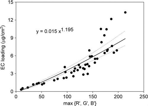
As the coefficient in EquationEquation (2) was a positive number and max{R’,G’,B’} was non-negative, any value of max{R’,G’,B’} of a filter, including a blank filter, would result in a positive estimation of EC loading. In accessing the lowest detection limit or sensitivity of the proposed method, signal of the blank filters was adopted as the background or baseline level. For a blank filter, the average max{R’,G’,B’} was 1.4, with 95% of max{R’,G’,B’} fell into the range of 0 to 6 (10,000 pixels, data not shown). Accordingly, the max{R’,G’,B’} value of 7 (corresponds to 0.153 μg/cm2) is therefore taken as the lowest detection limit of this proposed digital method.
Verification of the Estimation Model
The above estimation model was applied to the remaining 24 high-volume samples. The estimated values were compared with the values measured by thermal-optical method to test the applicability of digital imaging. shows the measured EC loading and the estimation. It was found that most of the measured values fell into the range of estimation. The model underestimated/overestimated four samples by more than 40%. The max{R’,G’,B’} values of these samples were either over 180 or below 30. As discussed above, max{R’,G’,B’} is not a linear function and it maximum value is 255, large increases of EC loading would only lead to a small increase in max{R’,G’,B’} when max{R’,G’,B’} is high. Therefore, the estimation error was large when the max{R’,G’,B’} was high and hence it was suggested that the estimation model should not be applied to samples having high max{R’,G’,B’} values. In addition, when the EC loading is small, the relative error was large, therefore it was also suggested that the estimation model should not applied to samples having low max{R’,G’,B’}. From , it was suggested that the above model should applied to samples having max{R’,G’,B’} values lie between 40 and 170, which corresponds to 1.2 to 6.8 μg/cm2 measured by thermal-optical method. It should be also noted that even though max{R’,G’,B’} is used, larger errors may be found in the samples with high metal loadings due to the comparable light absorbing coefficient of some metals as discussed in the previous section. Those samples include samples of dust storm and samples collected near ore-producing industries.
FIG. 6 Verification of the estimation model with 24 high volume samples. Circles (•) represent the measured EC loading while the solid line and dashed lines represent the estimation model and its 95% confidence interval.
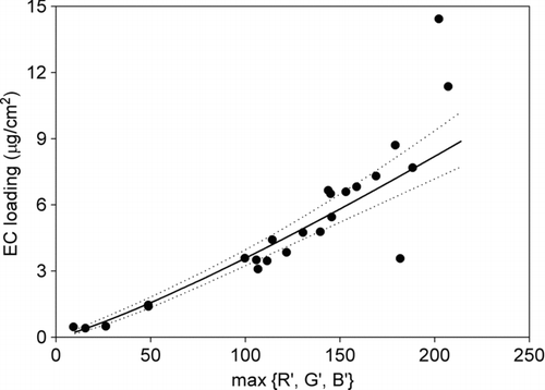
For the samples having max{R’,G’,B’} values lie between 40 and 170, the average of absolute percentage difference between the estimated values and measured values was 10.3% (range: 0.2–25.3%, n = 16). This 10.3% error is close to the assurance of the standard thermal-optical analyzer, e.g., 5–10% listed by Sunset Laboratory Inc. The proposed digital imaging approach using an office scanner appears to be a cost effective, user friendly, and relative precise (10.3% error) measurement means to quantify EC for educational purpose at high school environments.
CONCLUSIONS
This study had demonstrated the use of an office scanner to digitalize the colors of sampled filters for EC loading estimation. Although the presence of organic carbons and metals affects the color of filters, introduction of the new term, max{R’,G’,B’}, which represents the minimum value of red, green and blue intensities reflected by EC, could reduce the effect. It was found that the max{R’,G’,B’} was power-law related with EC loading. The amounts of EC collected on filters can be estimated by if the max{R’,G’,B’} fall into the optimal range of 40 to 170 with an average of 10.3% error. This study had proved in principle that digital imaging can be used to estimate airborne EC concentration. This method does not require expensive and complicated analytical tools, but an office scanner and Adobe software only; therefore this method can serve as an economical alternative for EC measurement.
Acknowledgments
The authors would like to thank Miss Alice Yip, Mr. T.H. Lam, Mr. C.W. Lee, Mr. H.H. Liu and Mr. H.T. Li for collecting and scanning the samples. The study is financially supported by the Quality Education Fund (Project No. 2008/0340).
REFERENCES
- Allen , G. A. , Lawrence , J. and Koutrakis , P. 1999 . Field Validation of a Semi-Continuous Method for Aerosol Black Carbon (Aethalometer) and Temporal Patterns of Summertime Hourly Black Carbon Measurements in Southwestern PA . Atmos. Environ , 33 : 817 – 823 .
- Baümer , S. , Versick , S. and Vogel , B. 2008 . Determination of the Visibility Using a Digital Panorama Camera . Atmos. Environ. , 42 : 2593 – 2602 .
- Birch , M. E. and Cary , R. A. 1996 . Elemental Carbon-Based Method for Monitoring Occupational Exposures to Particulate Diesel Exhaust . Aerosol Sci. Technol. , 25 : 221 – 241 .
- Cachier , H. , Bremond , M. P. and Buat-Ménard , P. 1989 . Determination of Atmospheric Soot Carbon with a Simple Thermal Methods . Tellus. , 41B : 379 – 390 .
- Cao , J. J. , Lee , S. C. , Chow , J. C. , Watson , J. G. , Ho , K. F. , Zhang , R. J. , Jin , Z. D. , Shen , Z. X. , Chen , G. C. , Kang , Y. M. , Zou , S. C. , Zhang , L. Z. , Qi , S. H. , Dai , M. H. , Cheng , Y. and Hu , K. 2007 . Spatial and Seasonal Distributions of Carbonaceous Aerosols Over China . J. Geophys. Res. , 112 : D22S11 doi:10.1029/2006JD008205
- Chow , J. C. and Watson , J. G. 2002 . PM2.5 Carbonate Concentrations at Regionally Representative Interagency Monitoring of Protected Visual Environment Sites . J. Geophys. Res. , 107 : D21, ICC6-1-ICC6-9 doi:10.1029/2001JD000574
- Chow , J. C. , Watson , J. G. , Louie , P. K. K. , Chen , L. -W. A. and Sin , D. 2005 . Comparison of PM2.5 Carbon Measurement Methods in Hong Kong, China . Environ. Pollut. , 137 : 334 – 344 .
- Doi , R. and Ranamukhaarachchi , S. L. 2007 . Soil Colour Designation Using Adobe Photoshop™ in Estimating Soil Fertility Restoration by Acacia auriculiformis Plantation on Degraded Land . Current Science. , 92 : 1604 – 1609 .
- Gelencsér , A. , Hoffer , A. , Kiss , G. , Tombácz , E. , Kurdi , R. and Bencze , L. 2003 . In-Situ Formation of Light-Absorbing Organic Matter in Cloud Water . J. Atmospheric Chem. , 45 : 25 – 33 .
- Gundel , L. A. , Dod , R. L. , Rosen , H. and Novakov , T. 1984 . The Relationship Between Optical Attenuation and Black Carbon Concentration for Ambient and Source Particles . Sci. Total Environ. , 36 : 197 – 202 .
- Hardeberg , J. Y. 2001 . Acquisition and Reproduction of Color Images: Colorimetric and Multispectral Approaches Retrieved from http://www.dissertation.com/index.php
- Hegglin , M. I. , Krieger , U. K. , Koop , T. and Peter , T. 2002 . Organics-Induced Fluorescence in Raman Studies of Sulfuric Acid Aerosols . Aerosol Sci. Technol. , 36 : 510 – 512 .
- Hitzenberger , R. , Petzold , A. , Bauer , H. , Ctyroky , P. , Pouresmaeil , P. , Laskus , L. and Puxbaum , H. 2006 . Intercomparison of Thermal and Optical Measurement Methods for Elemental Carbon and Black Carbon at an Urban Location . Environ. Sci. Technol. , 40 : 6377 – 6383 .
- Ho , K. F. , Cao , J. J. , Lee , S. C. and Chan , C. K. 2006 . Source Apportionment of PM2.5 in Urban Area of Hong Kong . J. Hazard. Mater. B , 138 : 73 – 85 .
- Horvath , H. 1993 . Atmospheric Light Absorption—A Review . Atmos. Environ. , 27A : 293 – 317 .
- Jacobson , M. Z. 2001 . Strong Radiative Heating Due to the Mixing State of Black Carbon in Atmospheric Aerosols . Nature. , 409 : 695 – 697 .
- Kendall , M. , Duarte , A. , Rocha-Santos , T. , Hamilton , R. and Williams , I. 2002 . Airborne Particulate-Associated Polyaromatic Hydrocarbons, n-Alkanes, Elemental, and Organic Carbon in Three European Cities . J. Environ. Monit. , 4 : 890 – 896 .
- Lam , K. S. , Cheng , Z. L. , Kot , S. C. and Tsang , C. W. 2004 . Chemical Characteristics of Aerosols at Coastal Station in Hong Kong. II. Environmental Behavior of Trace Elements During the April 1995 to April 1996 . J. Environ. Sci. , 16 : 212 – 221 .
- Lammel , G. and Novakov , T. 1995 . Water Nucleation Properties of Carbon Black and Diesel Soot Particles . Atmos. Environ. , 29 : 813 – 823 .
- Lee , C. S. L. , Li , X. D. , Zhang , G. , Li , J. , Ding , A. J. and Wang , T. 2007 . Heavy Metals and Pb Isotopic Composition of Aerosols in Urban and Suburban Areas of Hong Kong and Guangzhou, South China—Evidence of the Long-Range Transport of Air Contaminants . Atmos. Environ. , 41 : 432 – 447 .
- Lin , J. J. and Tai , H. S. 2001 . Concentrations and Distributions of Carbonaceous Species in Ambient Particles in Kaohsiung City, Taiwan . Atmos. Environ. , 35 : 2627 – 2636 .
- Offenberg , J. H. and Baker , J. E. 2000 . Aerosol Size Distributions of Elemental and Organic Carbon in Urban and Over-Water Atmospheres . Atmos. Environ. , 34 : 1509 – 1517 .
- Penner , J. E. and Novakov , T. 1996 . Carbonaceous Particles in the Atmosphere: A Historical Perspective to the Fifth International Conference on Carbonaceous Particles in the Atmosphere . J. Geophys. Res. , 101 : 19373 – 19378 .
- Rosen , H. , Hansen , A. D. A. , Gundel , L. and Novakov , T. 1978 . Identification of the Optically Absorbing Component in Urban Aerosols . Appl. Opt. , 17 : 3859 – 3861 .
- Seinfeld , J. H. and Pandis , S. N. 1998 . Atmospheric Chemistry and Physics , 700 New York : John Wiley & Sons .
- Sunset Laboratory Inc. 1996 . Sample Analysis Method for Organic and Elemental Carbon Aerosols , Sunset Laboratory .
- Tan , P. N. , Steinbach , M. and Kumar , V. 2006 . Introduction to Data Mining , 145 Boston : Addison Wesley .
- Urszula , T. , Arimoto , R. and Ray , B. J. 2001 . Color-Related Differences in the Chemical Composition of Aerosol-Laden Filters . Atmos. Environ. , 35 : 1703 – 1709 .
- Viidanoja , J. , Sillanpää , M. , Laakia , J. , Kerminen , V.-M. , Hillamo , R. , Aarnio , P. and Koskentalo , T. 2002 . Organic and Black Carbon in PM2.5 and PM10: 1 Year of Data from an Urban Site in Helsinki, Finland . Atmos. Environ. , 36 : 3183 – 3193 .
