Abstract
This work has focused on the development and evaluation of an experimental set-up to measure in real time and with on-board equipments the particle emissions of diesel vehicle minimizing the uncertainties associated to dilution ratio, the length of the transfer line and the sampling point in the engine exhaust pipe. Its suitability has been verified by ensuring the repeatability of the results in dynamometer tests reproducing standard circuits, as well as in closed circuits and in real urban traffic in Madrid, Spain. The experience derived from this work has been very useful, contributing to the advance in the measurement of particle number and size distribution in real time using on-board equipment and bringing us closer to understanding the relationship between the physical characteristics of the particles emitted by a diesel engine and its operation in real urban traffic conditions. The proposed on-board system has provided very satisfactory results.
1. INTRODUCTION
The inclusion of the measure of the number and distribution of particle size in the analysis of exhaust gases, taking into account the dynamic and operational behavior of the engine, is mainly due to the concern generated in the international community as a result of several epidemiological studies. These studies showed a correlation between particulate matter present in the environment and their health effects, especially in urban areas (CitationVedal 1997). The analysis of the environmental impact of nanoparticle emissions from the diesel vehicles requires the knowledge of both the primary particle emissions and the subsequent physico-chemical transformations of these particles occurring outside of the tailpipe, these transformations are usually studies with simulation models (CitationUhrner et al. 2007; CitationWehner et al. 2009). To get it the characterization of the primary particle from the source in-use conditions is necessary and this has motivated us to develop an on-board system able to measure and analyze the physical characteristics of particles that are being emitted by a vehicle in operation. The instrument has been tested in diesel engines with modern post-treatment systems when operating in real traffic conditions in a city like Madrid. This information is not available yet in any Spanish city, by measuring the exhaust gases directly from the exhaust pipe. The lack of commercial portable equipments, the complexity of the proper treatment of the gas sample, and the confined space of the passenger compartment of a car have limited, so far, the on-board measurement of particle emissions of a diesel engine in real traffic.
Measuring size and number distribution in particle emissions from the exhaust gases requires controlling the temperature and dilution of the sample gas (CitationBurtscher 2005; CitationShi et al. 1999; CitationVogt et al. 2003). Several authors reported a marked influence of the dilution ratio of the mixture, as well as the temperature and the humidity of the dilution air on the results (CitationKittelson et al. 1999). In the exhaust gases from a diesel engine, depending on the processes occurring, there may be phenomena that change the size and concentration of the measured particles. These phenomena include nucleation, condensation and coagulation (CitationAhlvik et al. 1998; CitationFriedlander 2000). Therefore, the saturation ratio is what spearheads the process of gas to particle conversion (CitationKim et al. 2002; CitationKittelson 1998). Considering that the dilution air temperature controls the temperature of the exhaust–air mixture to be analyzed, it is necessary to maintain a high enough mixture temperature to prevent saturation of gaseous species and thus avoiding the phenomenon of nucleation that would distort the measurement of the real number of gas particles from the exhaust system. This would cause the appearance of small particles by nucleation of gaseous species and would seriously compromise the validity of the trial due to its lack of repeatability because of the completely random characteristics in the formation of small particles (<50 nm) by nucleation and larger particles (>50 nm) by adsorption on the surface of the soot (CitationBurtscher 2005).
While there has been great progress in understanding the physical characteristics of particles emitted by a diesel engine, there are still major uncertainties about generation in urban traffic conditions, and even more about the generation of smaller particles. It is not clear if the increased generation of these smaller particles, in cars with modern after-treatment systems, is due to an incorrect treatment of the sample under the typical conditions of laboratory or is a characteristic of the engine (CitationMohr et al. 2006; CitationKittelson et al. 1999).
The direct introduction of exhaust gases in equipment like the EEPS could cause major damages, because its working conditions allow a maximum sample temperature of 42°C. Furthermore, the use of a highly particle concentrated sample would exceed the detection limit of the equipment. To achieve these two conditions in the sample, a dilution has to be made in two stages: a 1:1700 dilution ratio in hot conditions first, with a temperature of 180°C and a 1:2 dilution ratio in second place in cold conditions. These two dilutions should prevent the formation of new particles. During the first dilution at high temperatures, the nucleation are prevented by avoiding the vapor saturation and during the second dilution at room temperature, the coagulation of the emitted particles is prevented.
The goal of this work has been the development and evaluation in on-board conditions of a system to measure the size and number distribution from particle emission in a modern diesel engine, in real time and in real urban traffic conditions. The performance of the result has been evaluated by conducting three types of testing and three repetitions in each one of them. The experimentation was started by conducting standardized European driving cycles, ECE15 cycle or UDC (Urban Driving Cycle), in a 4 roller 509 mm diameter dynamometer chassis. The second was a test track. Finally, in the city of Madrid with real traffic conditions on peak and off peak hour proceeded in a way that made the reproduction of the driving conditions possible. The results have been highly satisfactory, the conclusion is that the system configured and evaluated is suitable for performing measurements in real time and in real world conditions.
2. EXPERIMENTAL INSTALLATION
2.1. Instrumentation
The main equipment device used to determine the number and size distribution was a real time particle size spectrometer (EEPS 3090, TSI Inc.) which has a total of 32 channels between 5 and 560 nanometers (EEPS sampling parameters are shown in ). This device uses a corona charger to put a predictable charge level on the particles. The charged particles are introduced near the center of a column. An electric field inside the column repels the particles outward, where they are measured using an array of precision electrometers connected to electrodes on the outside wall of the column. This arrangement allows for concentration measurements of multiple particle sizes simultaneously. It offers two main advantages: (1) its ability to give data every 0.1 s, a necessary feature to characterize the transient regime, and (2) the size range is suitable for emission measurement in modern diesel engines. However, the EEPS is an equipment designed to work under laboratory conditions and it is very sensitive to vibrations which make on-board operation very difficult. In addition it is also sensitive to high concentrations of particles and it is not able to work with temperatures above 42°C. However, despite these disadvantages, the EEPS has shown a good correlation with the CPC and ELPI in transient conditions (Zervas et al. 2006). Besides the EEPS, another important device is a rotating disk diluter for particulate emission (RD-379020A, TSI Inc.), which was chosen because of the high dilutions it allows, a critical aspect to avoid some phenomena that can alter the original sample. Furthermore, to measure gaseous emissions an on-board measuring system (OBS 2200, HORIBA Ltd.) was used as complementary instrument. This device was selected for its specific and unique design for use in real traffic conditions in diesel vehicles.
TABLE 1 EEPS sampling parameters
2.2. Set-Up
The final dilution system was selected taking into account the requirements of the devices and the pursuit of optimum thermodynamic conditions for the sample (CitationRubio et al. 2009). The shows the equipment distribution and some other relevant parameters such as the sampling line lengths and flow rates.
FIG. 1 Set-up for particle size distribution and gases measurement. (1) Exhaust pipe; (2) heater pipe; (3) dilutor test tube; (4) air dilution pipe; (5) hot diluted sample; (6) way out undiluted aerosol; (7) thermodilutor; (8) particle free and dry dilution air; (9) sample entry to EEPS; (10) EEPS; (11) flow meter; (12) on-board measurement system.
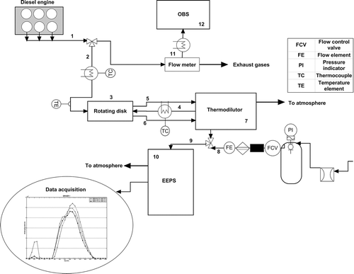
The exhaust gases were taken from the exhaust pipe by a tailpipe sample probe that was designed to avoid any perturbation in the flow caused by recirculation or detachment (1). The exhaust gases circulated through the heater pipe (2), which had a length of 1.6 m, minimum length necessary between the tailpipe and the sample probe of the rotating disk (3), and an 8 mm inner diameter. This sampling line must be as short and straight as possible to avoid the particle deposition, and losses due to both non-isokinetic sampling and diffusion. The theoretical particle diffusion losses (CitationCheng 1993; Hinds 1999) had an overall penetration efficiency of 85% in the particle range of 5.6 to 560 nm. Noting that the variability of the data was much higher than this percentage, it was decided not to correct the loss of particles in the sampling lines considering it negligible (CitationBergmann et al. 2009). On the other hand, the temperature of this heater pipe (2) was 180°C in order to prevent cooling of exhaust gases that can cause condensation and nucleation. Experiments suggest that nucleation mode particles are totally volatile and evaporate completely when heated up to 175°C (CitationDesantes et al. 2004; CitationLüders et al. 1998). Besides, heating is more important before the primary dilution stage where volatile species concentration and adsorption/condensation potential is maximum. Heating of the sampling lines decreases any thermal gradients from the flow to the boundary walls. This is a positive effect because it increases the homogeneity of the mixture and eliminates the losses of the particles due to thermophoresis. In general, it is advisable to avoid significant thermal gradients between the sample and its boundary walls which may provide a source of significant losses and aerosol variations (CitationNtziachristos et al. 2004).
The exhaust gases circulated through the heater pipe (2) to the rotating disk (3), which had an exhaust probe block with a warming temperature of 180°C. The flow rate of 1.5 l/min was constant and suctioned by the diluter probe.
Between the diluter probe (3) and the diluter main unit (7), there was another insulated pipe with a length of 0.7 meters that is the minimum length needed to develop the flow and optimum length to avoid the nucleation (CitationArmas et al. 2007), and an inner diameter of 4 mm, which heated up the air of the first dilution to 180°C (4). The first dilution had a DR of 1:1700 (according to the manufacturer recommendations), low dilution ratio could result in condensation and nucleation of sulphuric acid and semi-volatile organic compounds (CitationWang et al. 2006). After this dilution was performed, a second dilution (DR = 1:2) with particle-free dry air (a concentration below the detection limit of EEPS is guaranteed by a HEPA filter and an activated carbon filter) at ambient temperature was implemented, providing the 10 l/min that EEPS requires. The air needed for the second dilution was supplied by a diaphragm compressor with a 20 liter chamber needed to cushion the slug flow. 6 mm Teflon tubing was used for the diluted sampling line (9). The hypothetical route of the volatile organic compounds during the dilution process is shown in .
FIG. 2 Hypothetical route of the volatile organic compounds during two-step dilution. Phase diagram shows the concentration of volatile mass concentration vs. its temperature (CitationKasper 2004).
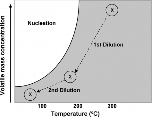
The first dilution (1:1700) is made at a temperature above 180°C maintaining this temperature in the transfer line, at this high temperature the probability of passing the nucleation zone during the first dilution is smaller with the consequent reduction of particle concentration corresponding to the nucleation mode. The nucleation phenomenon has been observed with the use of temperatures lower during the experimental tests.
To measure the concentration of particles, 1.5 l/min were extracted from the exhaust pipe as already described. The remaining flow passes through the flowmeter (11), a HORIBA pitot flowmeter of type B (included in the equipment associated with the OBS). Downstream of the flowmeter a sample of 3 l/min was extracted, flowing through a pipe heated at 190°C up to the OBS (12), for the measurement of NOx, CO2, and HC gases. All relevant parameters of the equipment are adjusted according to the calibration of this device (CitationAkard et al. 2005).
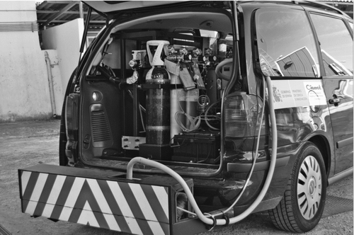
Once designed the layout of the system, we proceeded to carry out the installation inside the vehicle. A SEAT Alhambra minivan was selected for this purpose because it has enough volume for the installation of all measurement instruments and is also listed as a passenger car (selected as representative of a passenger car typical of Spain). shows the main characteristics of the SEAT Alhambra, a van equipped with a 2.0 TDI, 140 HP engine without Diesel Particulate Filter (DPF). The engine was a typical diesel engine used in the European car fleet.
TABLE 2 Engine characteristics
The equipment was fixed through a screwed structure over the vehicle chassis. The devices that are not designed for use in dynamic conditions (EEPS and diluter main unit) were cushioned by 4 symmetrically positioned silent blocks suitable for the weight of each one of the devices and the vibration conditions. On the other hand we proceeded to accomplish the necessary modifications for fulfilling every safety and legal aspect, as: distribution of the total equipment weight over the vehicle axle, control of the exhaust noise, elimination of sharp edges, etc. Once that was finished, the vehicle was homologated as mobile laboratory, according to the European normative (the result is shown in ).
In addition to the described devices, 4 batteries in the vehicle were installed to power the entire setup and to guarantee almost 4 h of autonomy, as well as 2 A/D converters, an UPS for the stabilization of the EEPS current, and other devices to complete the data, like a GPS, a weather station, etc.
3. TEST PLANNING AND THE EXPERIMENTAL PROCEDURE
Test planning was carried out to evaluate the measurement system of particulate emissions in size and number concentration. The experiments were developed using a European model diesel passenger car, whose key features were to be a EURO 4 vehicle, 2.0 l turbo-charged, direct injection (TDI) with oxidation catalyst. The vehicle was operated with European diesel fuel with sulphur levels of 10 ppm S, according to UNE EN 590.
Three sets of experiments of various kinds were performed to evaluate the measurement system of particle number and size distribution installed in the SEAT van.
The first experimental campaign was carried out in stationary conditions in a 4 roller 509 mm diameter dynamometer chassis. Six repetitions were performed of the ECE15 on two different days. At the beginning of each experimental day, the car was warmed on the chassis dynamometer at constant speed (50 km/h) for 10 min. Before each test, the engine car was driven at high load and high speed (preconditioning engine mode), in order to remove particulate matter that could be deposited in the walls of the exhaust pipe. The system installed in the van (section 2) is the same in all experiments. This experimental campaign was also used to evaluate the gas measurement system.
The on-board measurement was made on two types of tests, the first was in a test track, in the facilities of National Institute of Aerospace Technology (INTA) in Madrid, and the latter in the M-10 circuit that is the centre belt of Madrid city.
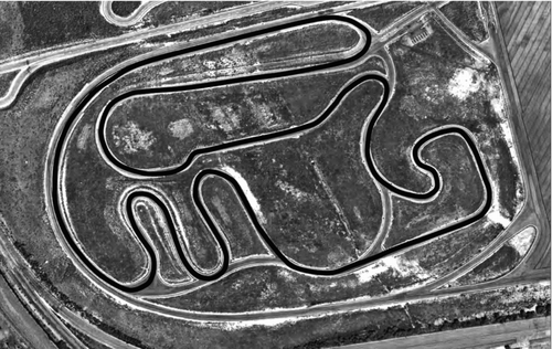
The test track on which the tests were conducted was a 2.1 km handling track (). Tests consisted of three repetitions with 2 different drivers at a speed of 60 km/h (maximum permissible speed for that circuit). All measurements were taken the same day.
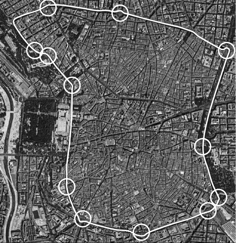
The last measurement campaign in the urban circuit was conducted by a single driver and 3 repetitions. The length of the circuit was 10 km and this circuit was selected because all of the urban and real traffic conditions of the city of Madrid are integrated (CitationDomínguez et al. 2009). The shows the route of the circuit (it was run counter-clockwise) with the straight sections and curves.
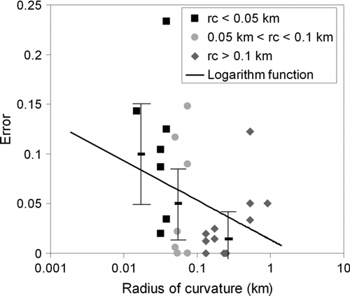
FIG. 5 Stretches of the city center of Madrid selected for the experiments. The circles correspond to the stretches with radius of curvature used in section 4.3.
All on-board experiments have been performed with the engine previously warmed up and in three different days.
4. RESULTS
4.1. System Response in Transient Regime
The experiments carried out at a transient chassis dynamometer were performed in order to evaluate the ability of the particle measurement system to perform real-time measurements. Another purpose of these experiments was to observe the repeatability of the data to confirm the proper functioning of the supposed thermodynamic behavior. Two kind of checking procedures were made: comparisons test-to-test and day-to-day with average total value of each emission in specific routes to observe the proper operation and evaluate the proposed assembly (CitationCocker et al. 2004; CitationWeaver and Petty 2004) and the different signals were mathematically synchronized taking into account the different delay times of each device previously measured. There were 6 repetitions in two different days of the ECE15 driving cycle, which reproduces the transient conditions of the engine. All measurements were performed with the EEPS installed outside the vehicle to prevent vibrations to distort the measure.
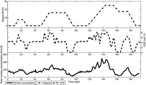
In measurements of gases made with the OBS2200 as well as in measurements of particles with the EEPS, the concentration of CO2 and NOx of ECE15 driving cycle the sharp increase in accelerations and sudden drop in decelerations for all speeds: 15, 30, 50, and 35 km/h are reflected. In general, the transient regime of the engine as can be seen in the ECE15 speed profile is reflected in the gas emission curves in the same way as particle emissions. The irregularities observed () in particles number concentration for constant speed or during the accelerations, were due to the difficulty associated with keeping the gas pedal stable for this conditions in a manually operated dynamometer, however, this variability in the position of the accelerator is followed by a response in the emission measure which shows the sensitivity of the developed system to small changes in engine operating conditions. The 6 repetitions performed of the ECE15 are represented.
FIG. 6 Speed profile (right axis) and total number particle concentration (left axis) measured in the urban part of ECE15 driving cycle (6 repetitions).
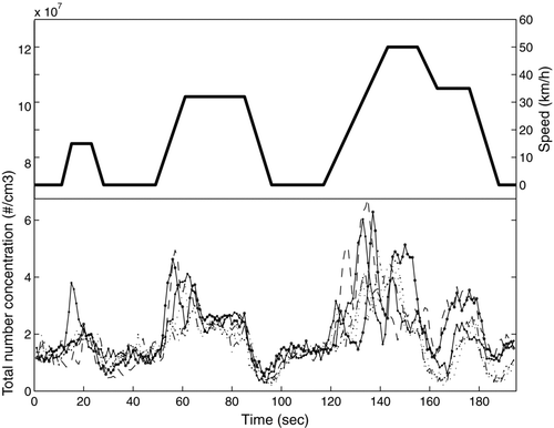
shows the total concentration of particles for the three stages that characterize the ECE15 driving cycle and all the measures follow the same pattern. This is particularly evident in the case of the different decelerations, while in the acceleration and in stable speed conditions are peaks of concentrations due to the instability of the gas pedal.
Looking at this graph, we see that for the acceleration to 15 km/h, the total concentration of achieved particles is 2E7 #/cm3. In the acceleration up to 30 km/h, the concentration is between 2E7 and 2.5E7 #/cm3. In the acceleration up to 50 km/h the total concentration is centered on 4E7 and 4.5E7 #/cm3 and at 35 km/h around a value of 2.5E7 #/cm3. Upon completion of all deceleration in the 3 stages, the concentration drops to values between 1E6 and 5E6 #/cm3. In idle periods, the average concentration is 8E6 #/cm3. These average values of particle total concentration are consistent with those reported by CitationBergmann et al. (2007) and CitationBergmann et al. (2009). The experiments show that the parameters measured had a similar response to the transitional regime. shows how the studied parameters have exactly the same response to the transitional regime, in this graph we can see that the changes in the slope of the velocity profile marked by the ECE 15 cycle are followed very well by the profile of particles and CO2 emissions.
The concentration of CO2, as well as the total particle had the same emission pattern, obtaining the same concentration peaks or sudden valleys. Transient data of total CO2, NOx gaseous emissions should accompany the total number particle measurement (CitationMaricq et al. 1999).
The emission test results are summarized in . The repeatability was measured with a coefficient of variability (standard deviation divided by the mean). The variability coefficient was less than 6% for gaseous emissions and for particle emissions less than 10%, thus the results showed repeatability (CitationWeaver and Petty 2004).
TABLE 3 Results of repeatability of all studied emissions for the ECE15C driving cycle
The most important conclusion that emerges from these results is the repetition pattern, both in magnitude of total concentration of all parameters measured as well as in the response to the transitional regime, for the 6 experiments of the urban part of ECE15 driving cycle.
4.2. Repeatability of On-Board Experiments
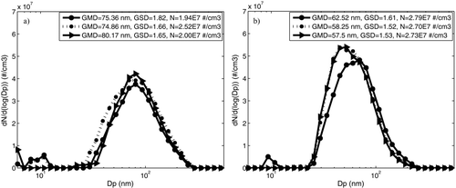
INTA experiments were the first developed with on-board measuring conditions. The purpose was to evaluate the measurement system under more demanding conditions than the real traffic conditions. The most adverse circuit, from the point of view of driving conditions, was selected () and was run at a speed of 60 km/h with two different drivers. The experiments were performed 3 times with each driver. Further study of data was carried out taking into account: total particle concentration (#/cm3), geometric mean diameter (GMD) and geometric standard deviation (GSD). The geometric parameters were obtained from the median curve of size distribution for each repetition and driver.
TABLE 4 Repeatability of number and size distribution in the facilities of INTA using different drivers
show the result of the different repetitions for each driver. The size distribution curve of the first driver was centered at higher values of GMD than the curve for the second driver. Similarly, the GSD for the first driver was always higher than for the second driver. The standard deviation of GMD, GSD, and N for the driver 1 was 3.68 nm, 0.09, and 1.62E6 #/cm3, respectively. The standard deviation of these values for the driver 2 was 2.71 nm, 0.05, and 4.85E5 #/cm3. However, considering the standard deviation of all the experiments together, the results for GMD, GSD, and N were 9.83 nm, 0.11, and 3.81E6 #/cm3. This shows that despite of the variations associated with different repetitions, the system was able to detect the influence of the driver.
shows the results of repeatability obtained by subjecting the vehicle to extreme driving conditions. The rank of repeatability is excellent both in size distribution and total number concentration (values less than 6%). Only the total concentration for driver 1 achieved a higher value, although not too high. The reason was that in one of the repetitions, driver 1 increased the mean speed, causing a higher emission of total number concentration of particles. This indicates a greater tendency for driver 1 to accelerate, causing an emission increased in particles larger than 70 nm (CitationBergmann et al. 2009), thus increasing the average GMD and average GSD.
4.3. System Response in Real Traffic Conditions
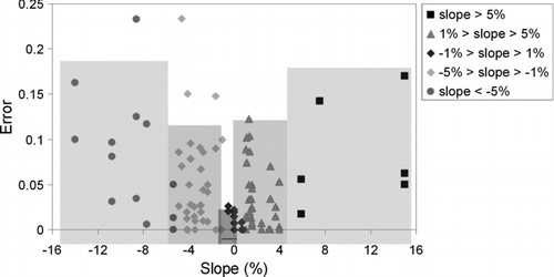
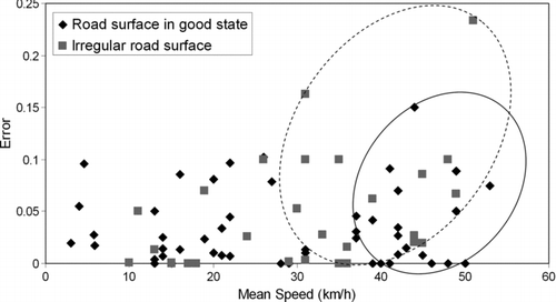
When measures are taken in real traffic, the equipment could not provide the desired response especially in sharp curves, steep slopes, or with some conditions of speed or in uneven pavement. The measures in real traffic are not isolated from vibration and loss of verticality on the equipment that are inside the vehicle causing instability in the measurements. Therefore, it is necessary to determine under what conditions the maximum measurement stability is ensured. To determine this, experiments were performed in the urban M-10 circuit, as described previously. This circuit has slopes ranging from –17% to 15%, radius of curvature lower than 0.05 km and different types of pavement: irregular and recently asphalted. The velocities considered for the analysis are the usual of the circuit, from 0 to 55 km/h. Taking into account these conditions, the circuit was divided in 43 stretches and afterwards the measurement error for each stretch was determined.
Measurement error (e) is defined as the number of unstable records (Ri) on the total number of records (Rt) for each stretch as in Equation (Equation1):
The stable condition of a record is:
This stability condition was obtained in a NEDC driving cycle measures. These measurements were quite stable because the equipment was out of the vehicle at the time of data collection, isolating it from external vibrations. In the stable measurement was observed that electrometers measuring sizes between 37.5 and 107.5 were not cancelled (0.00 #/cm3) under any condition (Equation (2)), while for the other sizes a reading of zero concentration could be possible. This value is different of the baseline, which is routinely obtained with HEPA filter before any measurement session.
The influence of the different variables on the error of the measurement and the error estimation is shown in Figures –.
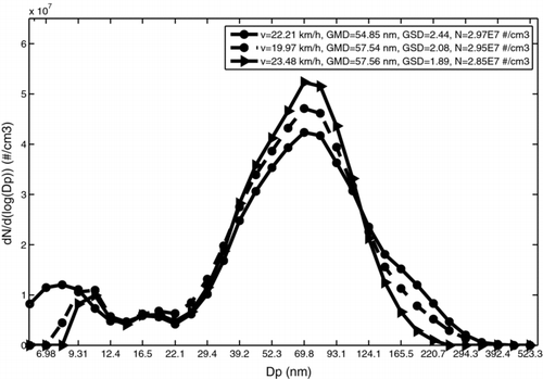
FIG. 12 Comparison of average particle size distribution of the 3 repetitions in the urban circuit M-10.
The measure is considered inaccurate when the error is more than 0.1. Given the estimation error (calculated with an ANOVA analysis of variance), we believe that when rc is less than 0.05 km (), the slope is above 5% or under –5% (dispersion data for these values of the slope as shown in ) and the speed exceeds 40 km/h with uneven pavement (), the measures have a too high error associated. Given these values, it is necessary to develop a preliminary study of its geographical characteristics and average speeds on the circuit, to minimize, as far as possible, errors associated with the on-board measurement.
Furthermore, these data were used to demonstrate the repeatability of the measure in real traffic conditions. The experiments were performed 3 times in 3 different days with only one driver. To avoid distortions caused by the error described, we applied the filter obtained in the experiments with the NEDC cycle. Further study of data was carried out taking into account: total particle concentration (#/cm3), geometric mean diameter (GMD), and geometric standard deviation (GSD). The geometric parameters were obtained from the median curve of size distribution for each repetition and with the applied filter. The lognormal size distribution and the characteristic parameters are shown in the .
The great similarity between the different size distribution curves indicates that the appearance of volatile compounds is negligible, thus ensuring that monitoring temperatures of pipes and temperature control of the dilution system are correct. Furthermore, the size distribution curve shows the occurrence of particles smaller than 20 nm, causing a decrease of the values of GMD and growth of GSD values. This size range was not present in the results of INTA measurements. The measures in urban traffic are characterized by high variations of speed, idle periods, fast accelerations, etc., which causes the appearance of particles of sizes below 20 nm. The variation in the appearance of these small particles causes the coefficient of variation of GSD is higher (). Still, the results of repeatability for urban real traffic conditions are excellent, taking into account the uncertainty of this type of measurement.
5. CONCLUSIONS
A system for measuring vehicle nanoparticles emissions in on-board conditions has been developed and tested. Quality assurance methods and procedures have been developed to ensure the accuracy and reproducibility of the emission measurements. This system has allowed us to minimize the influence on the results of the measures of new particles production processes due to coagulation phenomena, nucleation or condensation.
TABLE 5 Repeatability of particle number and size distribution in the results of M-10 circuit
As a result, the conclusions are:
-
Under stable laboratory conditions, the EEPS is able to respond to transient conditions of engine with response times similar to the OBS 2200 (Horiba Ltd). The response time (T0-90%) of the particle measurement system designed, based on the EEPS, is 13 s and in the OBS 2200 system is 8 s.
-
The results of particle number concentration and size distribution obtained during the on-board tests have shown a high degree of repeatability even when the experiments were carried out under the most demanding driving, demonstrating the robustness and reliability of the system.
-
From the experimental results obtained in NEDC cycle (New European Driving Cycle) with chassis dynamometer, the following limits for the operation of the system have been established: rc > 0.05 km, slope in the range ±5%, speed <40 km/h for uneven pavement. Outside of these conditions there is a high probability that there are failures in the response of the system with an incidence greater than 10% due to non controllable instabilities.
The results have been highly satisfactory, the final conclusion is that the on-board system configured and evaluated is suitable for the characterization of particulate in nanometric range in real time and in real traffic conditions.
Acknowledgments
The authors would like to thank Ignacio Estella for his support during the preparation of analysis of gaseous emissions and SEAT research laboratory for the support in technical aspects. This work was supported by the Ministerio de Medioambiente of Spain under contract grant 071/2006/3-13.2.
REFERENCES
- Akard , M. , Nakamura , H. , Shintaro , A. , Kihara , N. and Adachi , M. 2005 . Performance Results and Design Considerations for a New In-Use Testing Instrument . SAE Paper. , 2005-01-3606
- Ahlvik , P. , Ntziachristos , L. , Keskinen , J. and Virtanen , A. 1998 . Real Time Measurements of Diesel Particle Size Distribution with an Electrical Low Pressure Impactor . SAE Paper. , 980410
- Armas , O. , Gómez , A. and Herreros , J. M. 2007 . Uncertainties in the Determination of Particle Size Distributions Using a Mini Tunnel–SMPS System During Diesel Engine Testing . Meas. Sci. Technol. , 18 : 2121 – 2130 .
- Bergmann , M. , Kirchner , U. , Vogt , R. and Benter , T. 2009 . On-Road and Laboratory Investigation of Low-Level PM Emissions of a Modern Diesel Particulate Filter Equipped Diesel Passenger Car . Atmos. Environ. , 43 : 1908 – 1916 .
- Bergmann , M. , Scheer , V. , Vogt , R. and Benter , T. 2007 . Comparison of the Performance of Real-Time PM Mass and Number Instrumentation for Vehicle Exhaust Emissions . SAE Paper. , 2007-24-0116
- Burtscher , H. 2005 . Physical Characterization of Particulate Emissions from Diesel Engines: A Review . J. Aerosol Sci. , 36 : 896 – 932 .
- Cheng , Y. S. 1993 . Aerosol Measurement: Principles, Techniques, and Applications , Edited by: Baron , P. A. and Willeke , K. 435 – 436 . New York : Van Nostrand Reinhold . Condensation Detection and Diffusion Size Separation Techniques
- Cocker , D. R. III , Shah , S. P. , Johnson , K. , Miller , J. W. and Norbeck , J. M. 2004 . Development and Application of a Mobile Laboratory for Measuring Emissions from Diesel Engines. 1. Regulated Gaseous Emissions . Environ. Sci. Technol , 38 : 2182 – 2189 .
- Desantes , J. M. , Bermúdez , V. , Pastor , J. V. and Fuentes , E. 2004 . Methodology for Measuring Exhaust Aerosol Size Distributions from Heavy Duty Diesel Engines by Means of Scanning Mobility Particle Sizer . Meas. Sci. Technol. , 15 : 2083 – 2098 .
- Domínguez , A. , Rubio , J. R. and Barrios , C. C. 2009 . Influence of Road Traffic Conditions and Street Characteristics in Madrid City on Nanoparticle Vehicular Emissions [Abstract T083A20] . European Aerosol Conf. 2009 , Karlsruhe, Germany
- Friedlander , S. K. 2000 . Smoke, Dust, and Haze: Fundamentals of Aerosol Dynamics , 2nd ed. , 23 New York : Oxford University Press .
- Hinds , W. 1999 . Aerosol Technology: Properties, Behaviors, and Measurement of Airborne Particles , 146 New York : John Wiley & Sons .
- Kasper , M. 2004 . The Number Concentration of Non-Volatile Particles—-Design Study for an Instrument According to the PMP Recommendations . SAE Paper. , 2004-01-0960
- Kim , D. , Gautam , M. and Gera , D. 2002 . Parametric Studies on the Formation of Diesel Particulate Matter via Nucleation and Coagulation Modes . J. Aerosol Sci. , 33 : 1609 – 1621 .
- Kittelson , D. B. 1998 . Engines and Nanoparticles: A Review . J. Aerosol Sci. , 29 : 575 – 588 .
- Kittelson , D. B. , Arnold , M. and Watts , W. F. 1999 . Review of Diesel Particulate Matter Sampling Methods . Final Report, University of Minnesota ,
- Lüders , H. , Krüger , M. , Stommel , P. and Lüers , B. 1998 . The Role of Sampling Conditions in Particle Size Distribution Measurements . SAE Paper. , 981374
- Maricq , M. M. , Podsiadlik , D. H. and Chase , R. E. 1999 . Examination of the Size-Resolved and Transient Nature of Motor Vehicle Particle Emissions . Environ. Sci. Technol. , 33 : 1618 – 1626 .
- Mohr , M. , Forss , A. M. and Lehmann , U. 2006 . Particle Emissions from Diesel Passenger Cars Equipped with a Particle Trap in Comparison with other Technologies . Environ. Sci. Technol. , 40 : 2375 – 2383 .
- Ntziachristos , L. , Mamakos , A. , Samaras , Z. , Mathis , U. , Mohr , M. , Thompson , N. , Stradling , R. , Forti , L. and De Serves , C. 2004 . Overview of the European “Particulates” Project on the Characterization of Exhaust Particulate Emissions from Road Vehicles: Results for Light-Duty Vehicles . SAE Paper. , 2004-01-1985
- Rubio , J. R. , Domínguez , A. and Barrios , C. C. Design and Implementation of an On-Board Real Time Particle Measurement System [Abstract T083A21] . European Aerosol Conf. 2009 . Karlsruhe, Germany.
- Shi , J. P. , Harrison , R. M. and Brear , F. 1999 . Particle Size Distribution from a Modern Heavy Duty Diesel Engine . Sci. Total Environ. , 235 : 305 – 317 .
- Uhrner , U. , von Löwis , S. , Vehkamäki , H. , Wehner , B. , Bräsel , S. , Hermann , M. , Stratmann , F. , Kulmala , M. and Wiedensohler , A. 2007 . Dilution and Aerosol Dynamics within a Diesel Car Exhaust Plume—CFD Simulations of On-Road Measurement Conditions . Atmos. Environ. , 41 : 7440 – 7461 .
- Vedal , S. 1997 . Ambient Particles and Health: Lines that Divide . J. Air Waste Manag. Assoc. , 47 : 551 – 581 .
- Vogt , R. , Scheer , V. , Casati , R. and Benter , T. 2003 . On-Road Measurement of Particle Emission in the Exhaust Plume of a Diesel Passenger Car . Environ. Sci. Technol. , 37 : 4070 – 4076 .
- Wang , J. , Storey , J. , Domingo , N. , Huff , S. , Thomas , J. and West , B. 2006 . Studies of Diesel Engine Particle Emissions during Transient Operations Using an Engine Exhaust Particle Sizer . Aerosol Sci. Technol. , 40 : 1002 – 1015 .
- Weaver , C. S. and Petty , L. E. 2004 . Reproducibility and Accuracy of On-Board Emission Measurements Using the RAVEM™ System . SAE Paper. , 2004-01-0965
- Wehner , B. , Uhrner , U. , von Löwis , S. , Zallinger , M. and Wiedensohler , A. 2009 . Aerosol Number Size Distributions within the Exhaust Plume of a Diesel and a Gasoline Passenger Car under On-Road Conditions and Determination of Emission Factors . Atmos. Environ. , 43 : 1235 – 1245 .
- Zervas , E. and Dorlhene , P. 2006 . Comparison of Exhaust Particle Number Measured by EEPS, CPC, and ELPI . Aerosol Sci. Technol. , 40 : 977 – 984 .
