Abstract
Pollutant concentration is a major factor affecting exposure. Expiratory process generates high-velocity droplets for a very short period of time that leads to highly transient temporal and nonuniform concentration profiles. In this work, solid aerosol generated by an expiratory process was measured spatially and temporally inside a scaled ventilated chamber. Conventional ceiling-supply, ceiling-return, and displacement ventilation systems were studied. Two sizes of monodisperse microspheres, 0.05 and 10 μm, were generated by a modeled expiratory process. Two heated, scaled manikins were used to mimic a simple yet typical exposure scenario with an aerosol source and a receiver while buoyancy flow was presented. First, the influence of relative orientation of the source to the inlet diffuser on spatial concentration was investigated. The source was located in such a position that the bulk airflow was against to the expiratory process. Second, the relative orientation of the source-to-receiver was also investigated to study how the concentration distribution was being affected. Two orientations were tested as one of the source faced to the receiver and the other source faced to a sidewall. The dimensionless temporal concentration results were presented at six locations. Transient ventilation effectiveness was also evaluated and compared for both ventilation systems. With the “counter flow” scenario, the emitted particles tended to suspend in the mechanical ventilated chamber for a long period; this indicates a high exposure will be resulted. For the displacement scheme of the “face-to-wall” orientation, due to the low y-component of air velocity, poor lateral dispersion was observed.
INTRODUCTION
Since the outbreak of severe acute respiratory syndrome (SARS), there have been diverse research interests in controlling and reduction of human-to-human transmission of airborne infectious diseases. The very recent outbreak of Human Swine Influenza (H1N1) in May 2009 further aroused public alert on the airborne transmission pathway of highly contagious pathogens. Probably due to the specific functionality, many previous works on studying expiratory droplets have focused on the dispersion and transport of droplets in health care settings such as hospital wards or isolation rooms (CitationHuang and Tsao 2005; CitationWan et al. 2007; CitationRichmond-Bryant 2009; CitationZhao et al. 2009) and airliner cabins (CitationOlsen et al. 2003; CitationZhang and Chen 2007; CitationZhang et al. 2009). The conclusions drawn for these specific environments may not be applied directly to mechanical ventilated commercial buildings as the ventilation rate, indoor heat intensities, and surface-to-floor area ratios are substantially different.
In literature modeling expiratory process in ventilated chambers has been becoming an important topic in controlling the particles transport indoors (CitationZhao et al. 2005; CitationGao and Niu 2006; CitationZhang and Chen 2007; Berrouk et al. 2009; CitationRichmond-Bryant 2009). Nevertheless, experimental studies of the dispersion of expiratory droplets conducted in scaled, full-scale environmental chambers or rooms were scarce. CitationWan et al. (2007) have measured the dispersion characteristics of polydisperse droplets in a general hospital ward under a conventional ceiling-supply and return ventilation system. The results showed that the dispersions were strongly affected by the ventilation airflow pattern. CitationZhang et al. (2009) discussed the similarities and discrepancies of transport of gas contaminants and aerosols.
Prior to any contaminant control interventions are implemented to reduce exposure, it is essential to gain more fundamental understandings and knowledge on how expiratory droplets disperse and transport in ventilated spaces and how the emission characteristics, orientations, and droplet sizes affect the ultimate exposure. The global airflow pattern significantly affects the overall distribution of expiratory droplets (CitationLi et al. 2007). There are two ventilation systems being widely used, named mixing ventilation and displacement ventilation (DIS). A high-level supply and high-level return scheme (hereafter referred to well-mixed ventilation, or WM) is the most popular ventilation arrangement for commercial buildings. In this type, high-velocity cooled air is discharged from supply diffusers and warm air is extracted through return grills. For DIS systems, low-momentum cooled air is supplied to lower part of the room and exhausts hot air via ceiling return grills. The removal performance of the pollutants under WM schemes is mainly by high ventilation rate and turbulent deposition. The spatial concentration profile of the WM scheme is often assumed to be homogeneous. DIS utilizes completely different working principle. The removal mechanism works when a cool air parcel adsorbing heat inside the space, the air parcel rises, and carries pollutants such as particulate matter and viruses upward to the ceiling without any serious mixing internally (CitationZhao et al. 2004; CitationBolashikov and Melikov 2009; CitationMui et al. 2009). Previous studies using tracer gas to study ventilation effectiveness of DIS have shown its superior particle removal performance compared with the conventional well-mixed systems in steady-state measurements (CitationFriberg et al. 1996; CitationZhang and Chen 2006). Therefore, DIS is often characterized as a more effective ventilation system in removing contaminants and reducing the risk of cross contamination between occupants.
In literature, there were some studies concluding that exposure risk depends considerably on the relative direction of the airflow, the pollutant, and the worker (CitationFlynn et al. 1996; CitationCarlton and Flynn 1997). The authors have performed numerical modeling on how the work practices (position) affecting the ultimate exposure of massless particles and spray mists. They concluded that the orientation of the process with respect to airflow plays a significant role on the worker's exposure. However, the size distribution of the mist was not reported. Previous modeling work on aerosol distribution in a ventilated chamber gave useful information on a simple setting such as an infected person (the aerosol source or addressed as source hereafter) coughed face-to-face to another person (the receiver). This orientation is called “face-to-face” in this work. A few other plausible orientations that affect the ultimate exposure were explored but the infected person lay on a bed (CitationQian et al. 2006; CitationRichmond-Bryant 2009; CitationZhao et al. 2009). Very often in daily life the infected person is standing and expiratory droplets are emitted in a horizontal way. No literature result on aerosol distribution under this scenario has been studied. On the basis of daily observations and engineering judgment, the source emitting expiratory droplets toward a sidewall (called as “face-to-wall” orientation) can represent a minimum exposure as it is reasonably unlikely that the source can turn more than 90o before an expiratory process commences. The present author (Lai) has modeled droplet dispersion for both “face-to-face” and “face-to-wall” orientations in a single-zone environment under the WM and DIS schemes (CitationMui et al. 2009). Very significant reduction in exposure level was resulted from the “face-to-wall” orientation. The present authors have also measured aerosol concentration in a scaled mechanical ventilated chamber under both WM and DIS schemes (CitationLai and Wong 2010). Two heated manikins were placed inside the chamber to mimic a “face-to-face” orientation. The expiratory process was made parallel to the bulk airstream direction and was referred as “parallel flow” orientation hereafter. They concluded that for both ventilation schemes, the emitted aerosols can penetrate thermal boundary layers and travel long distance. The experimental results also confirmed the effective ventilation performance of the DIS scheme in light of the higher particle removal efficiency at most of the measuring locations.
For the current work, the transport of expiratory droplets was further investigated by including the effect of aerosol size and the different source-to-susceptible orientations under both conventional WM and DIS systems. Two monodisperse polystyrene latex (PSL) particles, 0.05 μm and 10 μm, were tested. The smaller one corresponds to virus while the larger one corresponds to bacteria. To the authors’ best knowledge, the measurement of spatial and temporal aerosol concentration in a chamber under different ventilation modes has not been reported in the literature. The current work provides very valuable data for studying droplets dispersion indoors.
EXPERIMENTAL SETUP AND PROCEDURE
Details of the Setup Description
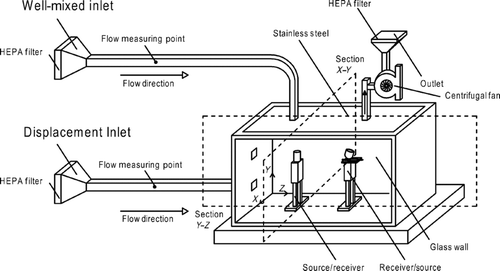
A high-quality tempered glass/stainless chamber was built () with dimensions of 0.5 × 0.5 × 1 m3 (H × D × W). The details of the chamber construction can be found elsewhere (CitationLai and Wong 2010), and hence it is briefly described here. It can be viewed as a 1:5 scaled mechanically ventilated chamber which was designed in a very flexible way that both WM and DIS schemes can be studied. The inlet duct length was sized at least 50 times of the hydraulic diameter of the size of the duct to ensure that the flow is fully developed at the chamber inlet. High efficiency particulate air (HEPA) filters were installed at both ends of the inlet and outlet ducts to minimize the background particle count inside the chamber and prevent cross contamination to the laboratory. The two manikins that are made of aluminum were heated by wrapping heating wire around the bodies. Air velocities were measured by hot wires that were calibrated prior to the measurement and the details can be found in the later section. It is important to mention that there was no intention to conduct scaling for the thermal aspects due to the physical restrictions imposed by the type of chamber used for the experiment.
Description of the Measuring Locations
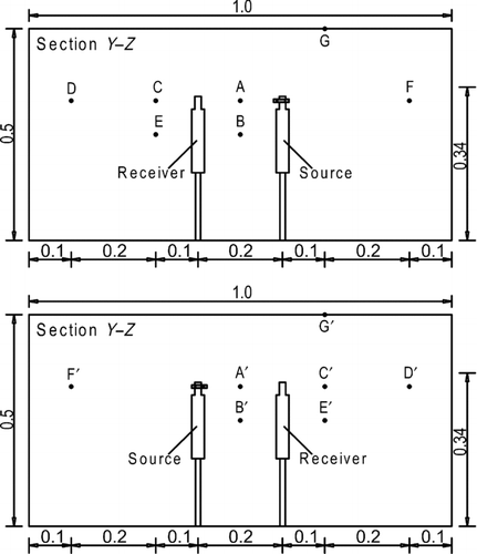
In the current study, the orientation of the expiratory process with respect to room airflow was investigated by arranging the direction of the injection opposing to the dominant airflow (source back toward the exhaust), hereafter referred to “counter flow” scenario. Owing to the expected particle trajectory w.r.t., the previous “parallel flow” scenario (source toward the exhaust outlet), the measurement locations were reselected carefully to capture the aerosol distribution characteristics upon the momentarily release. and b shows the arrangement of source and receiver manikins and the measuring points for both “counter flow” and “parallel flow” scenarios. The heights above the ground were chosen to represent exposure while standing and sitting. Two height levels were studied; 33 and 25 cm above the floor of the chamber. The height of 33 cm corresponds to a vertical height of 165 cm that can be used to assume the breathing level of a standing person. The height of 25 cm can be used to assume the breathing level of a sitting person that corresponds 125 cm in a full-scale room. For the “counter flow” measurements, the first location selected was at the mid-point between the two heated models at the horizontal level of the spray gun which is 33 cm above the floor and the location is referred to as Point A. Moving closer to the source was not suggested as the sampling tube would disturb the airflow. Point A represents the plausible worst case scenario among all current measurements, and hence the concentration was used to normalize all the other measuring points. Identical normalization process was used elsewhere (CitationLai and Wong 2010). Another location at the center was also selected to represent the sitting level, and it is referred as Point B. To investigate the exposure around the “receiver” and further downstream from the source manikin, three locations were selected near or beyond the receiver manikin. Two were at the same horizontal level of the spray gun with one of them along the same vertical axis of the supply outlet and the other being near the wall; these are referred to as Points C and D, respectively. Point E was located below C at the height of 25 cm above the floor. To gain more understandings on the concentration at the rear side of the source and to investigate how well the mixing could be achieved for both ventilation systems, Point F was chosen. There was one location selected at the exhaust to calculate the ventilation effectiveness which was labeled as Point G. Seven locations (Points A′, B′, C′, D′, E′, F′, and G′) were selected in a similar manner for the “parallel flow” measurements.
For the “face-to-wall” emission scenario (transverse to the exhaust), only two points were selected, as lateral transport was the key interest for this measurement. The first point is Point A as discussed for the “counter flow” scenario. Another chosen point, labeled as H, which was located at the rear side of the source was mounted at 33 cm above the horizontal ground along the axis of Point A. In order to compare the results with the “counter flow” and the “parallel flow” measurements, the same normalization process for the concentration was undertaken, i.e., the concentration level was normalized by the concentration measured at Point A of the emission process being faced toward the exhaust. The exact locations at which the particle concentration measurements were taken are recorded in .
Measuring locations of particle concentration for two different “face-to-face” orientations and “face-to-wall” scenario
Experimental Procedure
The detail procedure has been reported elsewhere (CitationLai and Wong 2010) and is only described briefly here. The temperature difference between the inlet air and the surface temperature of the manikins was kept at 20°C during the entire experimental period. The mean velocity for WM and DIS were set at 2 and 0.2 m/s, respectively. Expiratory velocity was kept at 10 m/s and was measured at Point A, which was located at the midpoint between the two heated models at the horizontal level of the spray gun placed 33 cm above the floor (0.1 m away from the spray gun). Prior to beginning of each experimental run, the velocity was measured. A portable hot-wire anemometer (Velocalc 9555, TSI) was utilized to measure the velocity, and the anemometer was calibrated by an automated calibrator (Model 1129, TSI). The concentration inside the chamber was measured by a condensation particle counter (3775, TSI). When the particle number concentration at Point A (or Point A′) dropped below 1000 per cm3 and became pseudo steady, the emission commenced. The spraying duration of 0.1 s (or 2 s for face-to-face scenario) was preset by a LabView program. Because only one counter was available, the concentration level was measured one point at a time, and it was very important to make sure the quantity of particles emitted each time was reasonably the same, otherwise, cross comparison of dimensionless results were resulted. Measurement at Point A was made prior the to beginning of the experiment, and it was measured two to three times. Experiments were not initiated until concentration level at Point A was close at each time. Each experimental run for every other location was replicated at least three times. If any observable deviation was found, additional sets of measurements were carried out.
Droplet Emission
Particles with a diameter larger than 10 μm generally will not be inhaled to deep lung region (International Commission on Radiological Protection [CitationICRP] 1994), therefore two particle sizes of 0.05 and 10 μm were selected, which represented large viruses and bacteria, respectively. Monodisperse particles of 0.05 and 10 μm were generated by atomization of diluted fluorescent polystyrene microsphere suspensions (Thermo Fisher Scientific). The expiratory process was mimicked by a short release of particles through a spray gun (180D Spray-Work, Tamiya) connected to a compressor. The diluted suspension was pre-filled to the cup container attached to the spray gun. The spray gun was fixed horizontally at the centerline (X = 0.25 m, Y = 0.33 m, Z = 0.6 m) of the head of the source in the “counter flow” measurements (). A flow regulating valve was used to adjust the emission velocity. The emission duration was controlled by a LabView program. The emission time for the “counter flow” scenario was set to 0.1 s. CitationMui et al. (2009) suggest that the influence of droplet size is not significant on droplet dispersion under a conventional mixing and a DIS schemes except for the “face-to-wall” orientation. Hence, only 0.05 μm was selected for investigating the transport characteristics under the “counter flow” scenario. Effects of particle inertia of the two aerosol sizes under both WM and DIS schemes were examined in the “face-to-wall” measurements. Nevertheless after conducting some trial runs for the experiments, it was found that very few particles were detected at Point A after the release. The emission period was then adjusted to 2 s to make certain of higher particle concentration was being recorded throughout the experiments.
RESULTS AND DISCUSSION
Characteristics of Expiratory Aerosol Dispersion and Concentration with the Two Ventilation Systems
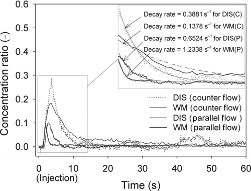
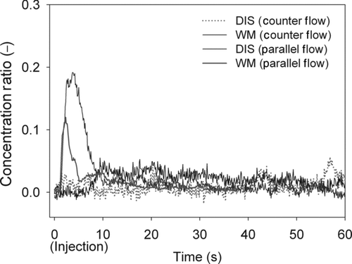
To study how the WM and DIS ventilation schemes affected spatial and temporal concentration for the “counter flow” arrangement after an expiratory process, the concentration of monodisperse aerosols for the measuring points of A to G at a different time were recorded. The results are shown in –. According to the experimental results for both ventilation schemes, the particles reached Point B at almost the same time after around 1 s of injection had elapsed (as shown in ). The expiratory aerosols were affected by the bulk airstreams under well-mixed system, in which the ambient air diluted the particle flows. Such phenomenon resulted in a lower peak concentration ratio of 0.18 at Point B for the WM scheme comparing with the peak concentration ratio of 0.29 for the DIS scheme. To investigate the particle removal mechanisms at the measuring points, decay curves were plotted for both ventilation schemes. It can be seen that the decay rate under the DIS scheme was higher than the WM scheme at Point B. It implies that the emitted particles can be effectively removed in the main airflow pathway in a short period under the DIS. It should be noted that the current decay rates of the WM and DIS schemes are higher than the ventilation rate, which were 0.02 and 0.004 s−1, respectively. It is due to an additional convection by the high-momentum airflow. However, comparing the results from the previous research for the “parallel flow” scenario (CitationLai and Wong 2010), the decay rates were lower for both ventilation schemes. It can be inferred that with the expiratory process toward the exhaust outlet the higher convection velocity promoted the lateral particle movements toward the exhaust, resulting of the higher decay constants. Similar finding was reported by CitationWan et al. (2007).
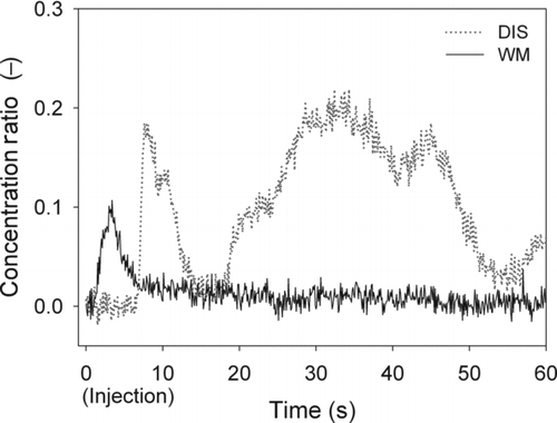
For the study reported here, the particles were carried by a high velocity of expiratory process. shows that the emitted particles could penetrate a long horizontal distance and reached at Point C for both ventilation schemes. Higher concentration profile was found for the DIS due to a lower air velocity along the emission direction in the chamber. With the supply outlet on the ceiling the particle concentration level decayed rapidly for the WM scheme in comparison with the DIS. It can be seen that a relatively high particle concentration ratio of 0.1 existed for more than 60 s for the DIS scheme, meanwhile the concentration level reached about 0.02 for the WM scheme. This implies that risk of infection remained at a reasonably high level for a certain long period after injection for the DIS. A plausible explanation is that particles can be retained in the stratified thermal layer for a long time outside the unidirectional airflow toward the exhaust in the DIS systems. shows that the emitted particles would not transport directly toward Point D after reaching Point C. The particles took 4.5 s longer to reach Point D from the Point C for the WM scheme. One observation made is that the peak concentration ratio of 0.06 was found under the WM, whereas there was no indicated variation in concentration under the DIS scheme when emissions were introduced. The results showed that higher concentration levels were found near the wall of the rear of the receiver under the parallel flow arrangement for both ventilation schemes. This implies that when the source emitted particles toward the exhaust outlet, the particles are able to travel a longer distance.
shows that the particles reached Point E with extra 5 s for the DIS scheme. Considering the location of the receiver, the emitted particles could not directly travel to Point E, therefore some particles traveled to that location at the later stage due to upward convective flow created by the heated manikins (Tsai et al. 2006). One interesting observation made is that a second peak concentration level of around 0.2 was recorded after 30 s of emission. This might be caused by re-entrainment of a portion of particles from other regions in the chamber. The findings reveal that receiver sitting at the lower zone may be subjected to high exposures to the pathogen-laden expiratory aerosols for the “counter flow” scenario despite the fact that dilution enhanced by the fresh air supplied from the lower level in the DIS scheme. The finding contradicts a previous observation for dispersion of a continuous exhaled droplet nuclei under the DIS system in which better indoor air quality at the lower zone was reported (CitationQian et al. 2006). Comparing the two ventilation schemes, the expiratory aerosols traveled to the measuring point quickly and were diluted by ambient air for the WM scheme.
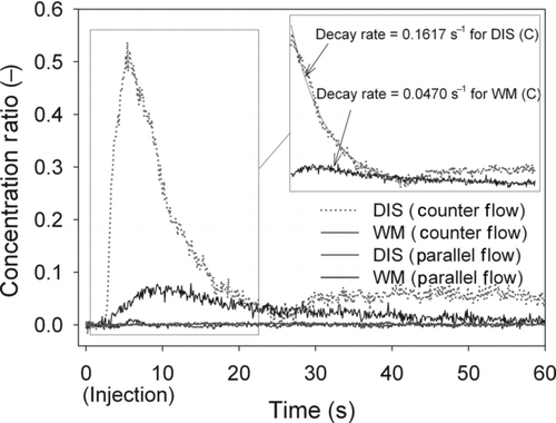
shows that the peak aerosol concentration level of 0.54 was recorded at 5.4 s at Point F for the DIS scheme in the “counter flow” scenario, while the WM reached its peak of 0.07 at 7.3 s. The data also showed that relatively high exposure level was maintained at the upper part of the testing chamber in a longer period for the DIS. This suggests that thermal stratification plays a significant role in locking expiratory aerosols in the upper zone with the DIS. Another observation is that there was no obvious variation in concentration levels under both ventilation schemes in “parallel flow” arrangement when emissions were introduced. This implies that the exhaust vent promoted the particle flow toward its position. There is high infection risk in people who are located near the exhaust vent even the expiratory process has been taken place back toward them.
In practical situation, aerosol loss by ventilation overwhelms the other fate mechanisms. CitationLai (2002) has published a review paper on particle deposition. For turbulent and Brownian diffusion, inferring from those collected data, it could be calculated that the deposition loss rate of 0.05 μm was about 0.5 h−1. For the present work, the loss rates due to ventilation were 7.2 and 72 h−1 for displacement and well-mixed schemes, respectively. The loss rate due to ventilation was at least an order of magnitude higher than that deposition. Electrostatic charges can enhance deposition loss. In the current work, aerosols may be charged during the generation process. A recent experimental study measured the electrostatic charges for aerosols generated by atomizers. The results revealed that averaged charges carried by each aerosols are very low for 0.05 μm aerosols, and hence it could be neglected in the current study.
Ventilation Performance in Removing Expiratory Aerosols under Two Different Injection Directions
Another quantitative measure that can also be used to investigate the effectiveness of the two ventilation systems in removing contaminated particles is transient ventilation effectiveness, ϵ. It is defined as
Transient ventilation effectiveness (ϵ) of the measuring positions for (a) “counter flow” and (b) “parallel flow” scenarios under both ventilation schemes.
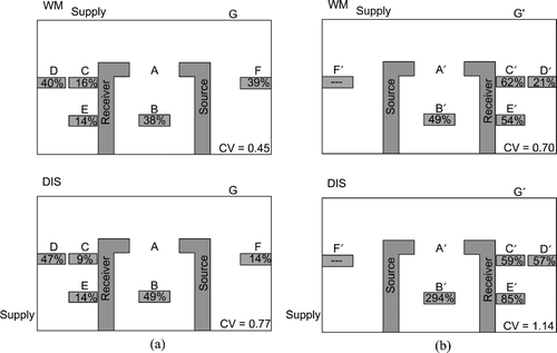
We also find that the DIS is only more effective in removing particles in the lower zone under “parallel flow” arrangement, as shown by ϵ values of 294% and 85% for Points B′ and E′, respectively. Under this condition, the upward convective flow plays a significant role in reducing the transport rate of the nonbuoyant particles from the upper zone to the floor level. A similar experimental observation has been reported in a study of a unidirectional upward system for the effective removal of small droplet nuclei (CitationWan and Chao 2007). However, also shows that the CV of the DIS under the “counter flow” arrangement was comparable to the two WM schemes for removing expiratory aerosols. This reveals that the design of the location of supply and exhaust outlets and the orientation of expiratory droplets play significant role in reduction of infectious disease risks.
Effect of Aerosol Size
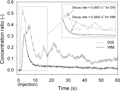
shows the temporal concentration profiles at Point H for the two aerosol sizes (0.05 and 10 μm) under the “face-to-wall” scenario. It can be seen that the emitted particles reached the measuring point in around 2 s after injection for the WM schemes, while the DIS schemes required extra 6 s to reach that location. This implies that in displacement ventilated rooms, low global air velocity cannot disperse the expiratory aerosols efficiently to other part of the room if expiratory process has taken place outside the main airstream. It is also observed that due to the high y-axis transverse velocity, the particle concentration approaches to background level at about 200 s for both sizes of aerosols under the WM scheme. Under the DIS scheme, due to a much lower turbulent airflow, only moderate inhomogeneous concentration can be noticed at the 200 s, dropping to 13% and 32% of the peak concentration level for aerosols with 0.05 and 10 μm diameters, respectively, after the emission. The results showed that the emitted particles could not be effectively entrained into the body thermal plume with the DIS and were exhausted out of the chamber. This phenomenon will lead to increase the degree of exposure level outside of the unidirectional airflow path due to a low concentration of expiratory aerosols being maintained persistently in that region.
Particle concentration profiles of 0.05 and 10 μm aerosols at Point H for “face-to-wall” orientation under both ventilation schemes.
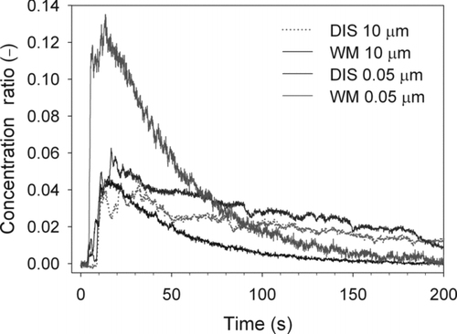
When comparing the concentration ratio for the two different sizes, it can be seen that the peak concentration of the 10 μm cases are lower than those of the 0.05 μm. It can be attributed to the relaxation time number (τ=D 2 p ρ p Cc /18η) where Dp is the particle diameter, ρp is the particle density, Cc is the Cunningham correction factor, and η is the gas viscosity. The relaxation times are calculated as 3.3 × 10⁻⁴ s and 4.2 × 10⁻⁸ s for 10 μm and 0.05 μm, respectively. Large relaxation time leads to head-on collision onto the wall and splashed fluorescent were even seen by naked eyes (CitationLai 2002). In contrast, dispersion of the small size particles was more significantly influenced by the airflow pattern of both ventilation systems (CitationChen and Zhao 2010). The decay rates for the smaller aerosols were higher than those for the larger size in both ventilation systems. Our results indicated that dispersion of aerosols is size dependent in a mechanical ventilated space (CitationSze To et al. 2009). Comparing and , it can be seen that lower decay rates under both ventilation schemes resulted in a poor mixing characteristic of the “face-to-wall” orientation by comparison with the two “face-to-face” orientations. This phenomenon was attributable to the low convective transport in the y-direction of the chamber that has been reported previous (CitationMui et al. 2009). On the basis of these findings, it can be concluded that the risk of exposure to pathogen-laden expiratory aerosols is dependent on the ventilation scheme, the particle size, and the emission direction.
It should be noted that aerosol resuspension can lead to second exposure. Coarse particles settle on floors dominantly. Under sufficient disturbance, they resuspend and become airborne and transport to other areas. Nevertheless for small particles such as 0.05 μm, they are very difficult to be resuspended in indoor environments (CitationThatcher and Layton 1995).
LIMITATIONS
The simple geometry approach adopted in the current work will facilitate computational fluid dynamic (CFD) validation. Yet it is understood that there are a few limitations. Owing to the constraints of the experimental setup and equipment, i.e., the physical size of the chamber was limited and the accuracy of the hot-wire anemometer was very low at velocity lower than 0.2 m/s. The body temperature of the manikins was limited by the electric current and could not reach over 10°C above the background temperature. This constraint led to lower Rayleigh number under the experimental conditioning. It implies that smaller bouyancy effect would be antipicated in the current study. Hence, comparing the current results with those obtained in practical scenarios should be cautious. Having said that it is still observed that ventilation rate is the predominant factor affecting particle dispersion.
CONCLUSION
A recent review article has studied how building ventilation affects airborne pathogen transmission (CitationLi et al. 2007). The risk of infection depends on the pathogen concentration (CitationNicas et al. 2005). Current experimental study on aerosol distribution in indoor environment is scarce. The current study is the first literature that reports the dispersion characteristics for an unsteady expiratory process under the well-mixed and DIS systems in a testing chamber. The objective of the present work is to provide accurate experimental results under two distinct airflow environments. It is not our intention to compare the current results with those obtained in practical scenarios directly. The entire setup was designed in a simple realistic ways so that CFD can be modeled in a straightforward manner.
The effect of three different source-to-receiver orientations are (i) source toward the exhaust, (ii) source back toward the exhaust, and (iii) source toward the wall, as well as the effect of aerosol size were investigated. Relatively uniform particle concentration ratios were observed for both “face-to-face” orientations under the WM system, resulting in higher concentration levels in other regions of the chamber in comparison with those measured under the DIS system. It was found that the particle emitted from the source could travel a longer horizontal distance under the “parallel flow” scenario than those with the “counter flow” scenario. This suggests that the direction of the main airflow stream promotes the transport of expiratory aerosols toward the exhaust vent. The results also indicate a high risk of infection if the receiver is located near the exhaust vent even the expiratory process being taken place back toward the exhaust. Under the DIS scheme, receiver sitting at the lower zone may be subjected to high exposures to the pathogen-laden expiratory aerosols for the “counter flow” scenario despite the fact that dilution was enhanced by the fresh air supplied from the lower level. The finding contradicts our previous observation for dispersion of exhaled droplet nuclei for the “parallel flow” arrangement under the DIS system in which better indoor air quality at the lower zone was reported.
With the “counter flow” scenario the emitted particles tended to suspend in the mechanical ventilated chamber for a long period; this indicates a high exposure will be resulted. Except for the “parallel flow” scenario, there is no evidence that the DIS has better particle removal efficiency than the WM in light of the similar ventilation effectiveness recorded at most of the measuring points. The results show that the “counter flow” arrangement promotes particle dispersion and mixing for both ventilation schemes. Previous experimental studies have made similar observation that the orientation of work process (i.e., spraying) w.r.t. bulk airflow is a major determinant of the ultimate exposure (CitationHeitbrink et al. 1995). For displacement scheme of the “face-to-wall” orientation, due to the low y-component air velocity and the locking effect, poor lateral dispersion was observed. It implies that aerosols with high inertia may be distributed weakly in some scenarios such as face-to-wall in our current study.
Acknowledgments
This article was partially supported by a grant from CityU 7002592.
REFERENCES
- Berrouk , A. S. , Lai , A. C. K. , Cheung , A. C. T. and Wong , S. L. 2009 . Experimental Measurements and Large Eddy Simulation of Expiratory Droplet Dispersion in a Mechanically Ventilated Enclosure with Thermal Effects . Build. Environ , 45 : 371 – 379 .
- Bolashikov , Z. D. and Melikov , A. K. 2009 . Methods for Air Cleaning and Protection of Building Occupants from Airbrone Pathogens . Build. Environ. , 44 : 1378 – 1385 .
- Carlton , G. N. and Flynn , M. R. 1997 . A Model to Estimate Worker Exposure to Spray Paint Mists . Appl. Occup. Environ. Hyg. , 12 : 375 – 382 .
- Chen , C. and Zhao , B. 2010 . Some Questions on Dispersion of Human Exhaled Droplets in Ventilation Room: Answers from Numerical Investigation . Indoor Air , 20 : 95 – 111 .
- Flynn , M. R. , Lackey , B. D. and Muthedath , P. 1996 . Experimental and Numerical Studies on the Impact of Work Practices Used to Control Exposures . Am. Ind. Hyg. Assoc. J. , 57 : 469 – 475 .
- Friberg , B. , Friberg , S. , Burman , L. G. , Lundholm , R. and Ostensson , R. 1996 . Inefficiency of Upward Displacement Operating Theatre Ventilation . J. Hosp. Infect. , 33 : 263 – 272 .
- Gao , N. and Niu , J. 2006 . Transient CFD Simulation of the Respiration Process and Inter-Person Exposure Assessment . Build. Environ. , 41 : 1214 – 1222 .
- Heitbrink , W. A. , Wallace , M. E. , Bryant , C. J. and Ruch , W. E. 1995 . Control of Paint Overspray in Autobody Repair Shops . Am. Ind. Hyg. Assoc. , 56 : 1023 – 1032 .
- Huang , J. and Tsao , S. 2005 . The Influence of Air Motion on Bacteria Removal in Negative Pressure Isolation Rooms . HVAC&R Res , 11 : 563 – 585 .
- ICRP . 1994 . “ Huamn Respiratory Tract Model for Radiological Protection ” . In Annals of International Commission on Radiological Protection, Publication 66 , Tarrytown , NY : Elsevier Science .
- Lai , A. C. K. 2002 . Particle Deposition Indoors: A Review . Indoor Air , 12 : 211 – 214 .
- Lai , A. C. K. and Wong , S. L. 2010 . Experimental Investigation of Exhaled Aerosol Transport under Two Ventilation Systems . Aerosol Sci. Technol. , 44 : 444 – 452 .
- Li , Y. , Leung , G. M. , Tang , J. W. , Yang , X. , Chao , C. Y. H. , Lin , J. Z. , Lu , J. W. , Nielsen , P. V. , Niu , J. , Qian , H. , Sleigh , A. C. , Su , H. -J. J. , Sundell , J. , Wong , T. W. and Yuen , P. L. 2007 . Role of Ventilation in Airborne Transmission of Infectious Agents in the Built Environment—A Multidisciplinary Systematic Review . Indoor Air , 17 : 2 – 18 .
- Mui , K. W. , Wong , L. T. , Wu , C. L. and Lai , A. C. K. 2009 . Numerical Modeling of Exhaled Droplet Nuclei Dispersion and Mixing in Indoor Environments . J. Hazard. Mater. , 167 : 736 – 744 .
- Nicas , M. , Nazaroff , W. W. and Hubbard , A. 2005 . Toward Understanding the Risk of Secondary Airborne Infection: Emission of Respirable Pathogens . J. Occup. Environ. Hyg. , 2 : 143 – 154 .
- Olsen , S. J. , Chang , H. L. , Cheung , T. Y. Y. , Tang , A. F. Y. , Fisk , T. L. , Ooi , S. P. L. , Kuo , H. W. , Jiang , D. D. S. , Chen , K. T. , Lando , J. , Hsu , K. H. , Chen , T. J. and Dowell , S. F. 2003 . Transmission of Severe Acute Respiratory Syndrome on Aircraft . New Engl. J. Med. , 349 : 2416 – 2422 .
- Qian , H. , Li , Y. , Nielsen , P. V. , Hyldgaard , C. E. , Wong , T. W. and Chwang , A. T. Y. 2006 . Dispersion of Exhaled Droplets Nuclei in a Two-Bed Hospital Ward with Three Different Ventilation Systems . Indoor Air , 16 : 111 – 128 .
- Richmond-Bryant , J . 2009 . Transport of Exhaled Particulate Matter in Airborne Infection Isolation Rooms . Build. Environ. , 44 : 44 – 55 .
- Sze To , G. N. , Wan , M. P. , Chao , C. Y. H. , Fang , L. and Melikov , A. 2009 . Experimental Study of Dispersion and Deposition of Expiratory Aerosols in Aircraft Cabins and Impact on Infectious Disease . Aerosol Sci. Technol. , 43 : 466 – 485 .
- Thatcher , T. L. and Layton , D. W. 1995 . Deposition, Resuspension, and Penetration of Particles within a Residence . Atmos. Environ. , 29 : 1487 – 1497 .
- Tsai , C. J. , Lin , J. S. , Deshpande , C. G. and Liu , L. C. 2006 . Electrostatic Charge Measurement and Charge Neutralization of Fine Aerosol Particles during the Generation Process . Part. Part. Syst. Char. , 22 : 293 – 298 .
- Wan , M. P. and Chao , C. Y. H. 2007 . Transport Characteristics of Expiratory Droplets and Droplet Nuclei in Indoor Environments with Different Ventilation Air Flow Patterns . J. Biomech. Eng.-T. ASME , 129 : 341 – 353 .
- Wan , M. P. , Chao , C. Y. H. , Ng , Y. D. , Sze, To , G. N. and Yu , W. C. 2007 . Dispersion of Expiratory Droplets in a General Hospital Ward with Ceiling Mixing Type Mechanical Ventilation System . Aerosol Sci. Technol. , 41 : 244 – 258 .
- Zhang , Z. and Chen , Q. 2006 . Experimental Measurements and Numerical Simulations of Particle Transport and Distribution in Ventilated Rooms . Atmos. Environ. , 40 : 3396 – 3408 .
- Zhang , Z. and Chen , Q. 2007 . Comparison of the Eulerian and Lagrangian Methods for Predicting Particle Transport in Enclosed Spaces . Atmos. Environ. , 41 : 5236 – 5248 .
- Zhang , Z. , Chen , X. , Mazumdar , S. , Zhang , T. and Chen , Q. 2009 . Experimental and Numerical Investigation of Airflow and Contaminant Transport in an Airliner Cabin Mockup . Build. Environ. , 44 : 85 – 94 .
- Zhao , B. , Yang , C. , Chen , C. , Feng , C. , Yang , X. , Sun , L. and Yu , W. G. 2009 . How Many Airborne Particles Emitted from a Nurse will Reach the Breathing Zone/Body Surface of the Patient in ISO Class-5 Single-Bed Hospital Protective Environments?—A Numerical Analysis . Aerosol Sci. Technol. , 43 : 990 – 1005 .
- Zhao , B. , Zhang , Y. , Li , X. , Yang , X. and Huang , D. 2004 . Comparison of Indoor Aerosol Particle Concentration and Deposition in Different Ventilated Rooms by Numerical Method. . Build. Environ. , 39 : 1 – 8 .
- Zhao , B. , Zhang , Z. and Li , X. 2005 . Numerical Study of the Transport of Droplets or Particles Generated by Respiratory System Indoors . Build. Environ. , 40 : 1032 – 1039 .
