Abstract
A fast approach to calculate scanning differential mobility analyzer (DMA) transfer functions is introduced. The trajectory-based approach of Dubey and Dhaniyala (2008, Analysis of Scanning DMA Transfer Function. Aerosol Sci. Technol., 42:544–555) is extended to determine mobility-based transfer functions of diffusional particles in scanning DMAs. The mobility-based transfer functions are obtained from the transformation of calculated arrival-times of the particles of a selected mobility, i.e., the arrival-time transfer function (ATF). The ATFs are calculated from Monte Carlo simulations of the motion of particles of different diameters, under a range of DMA operating conditions. The results suggest that the nondiffusional ATFs for up-scan operation can be approximated as triangular in shape and the diffusional ATFs as Gaussian. The simulation results show that for high-voltage operation, the effect of fast scanning determines the measurement resolution, while for low-voltage operation, the effect of diffusion is most important. An approach to calculate the instrument transfer function based on the ATF area and resolution is described. The transfer functions calculated by the new fast approach match well with those obtained from Monte Carlo simulations.
INTRODUCTION
The differential mobility analyzer (DMA) is a popular instrument for the study of physical characteristics of ultrafine particles. In particular, they are widely used for the classification of particles by their electrical mobility. In combination with an upstream particle charger that results in mostly singly charged particles (e.g., bipolar radioactive chargers), the DMA can be used to output nearly monodisperse particles. These particles can be analyzed with a variety of aerosol instruments for measurement of a large range of particle properties (CitationPark et al. 2008). One standard application of the DMA is for size distribution measurements, where the classifier voltage is varied and the classified particles are counted downstream of the DMA. Accurate calculation of size distributions from DMA-based measurements is strongly dependent on the accurate knowledge of the instrument transfer function, i.e., the probability of transmitting particles of different mobilities or diameters through the DMA sample flow for a selected classifier voltage.
For a fixed-voltage operation, theoretical expressions for DMA transfer functions are available for both nondiffusive (CitationKnutson and Whitby 1975) and diffusive particles (CitationStolzenburg 1988). These transfer functions are appropriate for size distribution measurements with a differential mobility particle sizer (DMPS), where the DMA is operated in a stepping voltage configuration and the downstream particle count data is recorded at constant voltages. For faster measurements, CitationWang and Flagan (1990) introduced the concept of a scanning electrical mobility spectrometer (SEMS). CitationWang and Flagan (1990) showed that, with an exponential voltage variation, the DMA transfer functions are invariant over the entire range of classification voltages. With the SEMS technique, accurate size distribution measurements are possible in approximately 2–5 min (considering typical operation with a TSI 3071 DMA).
For slow scan rates, size distributions can be determined from SEMS measurements assuming that the scanning DMA transfer functions are the same as the fixed-voltage ones. At faster scan rates, however, the nonidealities in the system become important and must be considered. One nonideality is the effect of particle concentration smearing that occurs because of flow mixing in the condensation particle counter (CPC) and the transport pathways between the DMA and CPCs. The desmearing of fast scan data has been shown to be possible by using iterative approaches (CitationCollins et al. 2002).
The other significant nonideality is associated with the distortion of the DMA transfer function during fast scanning. CitationCollins et al. (2004)used Monte Carlo (MC) simulations to show that the transfer functions of a DMA operated under fast scanning are significantly different from that operated with a fixed voltage. It was seen that for a cylindrical DMA, the transport of particles in a temporally and spatially varying electric field, as occurring in a scanning DMA, results in a broadening of the range of mobilities being classified in a counting interval, over that obtained with a fixed-voltage DMA. The MC approach is, however, computationally expensive and does not permit fast transfer function calculation. Using a new trajectory-based approach, CitationDubey and Dhaniyala (2008) showed that scanning DMA transfer functions for a selected DMA geometry and operating conditions can be obtained in near real-time. In that work, the transfer functions were obtained from the solution of a limited number of trajectory calculations, minimizing computational time. That work, however, did not consider the simultaneous effect of diffusion and scanning on the DMA transfer functions, thus limiting our ability to calculate size distributions of diffusive particles from a fast scan measurement. Here, a computationally simple approach to transform fixed-voltage diffusive DMA transfer functions to scanning diffusive DMA transfer functions is described, permitting the near real-time determination of DMA transfer functions under a scanning operation for a broad range of particle sizes.
ARRIVAL-TIME TRANSFER FUNCTION
To obtain the nondiffusive scanning DMA transfer functions, CitationDubey and Dhaniyala (2008) used a two-step calculation approach; the first step involved determination of the arrival-time transfer function (ATF), and in the second step, the ATF was transformed to a mobility-based transfer function. For particles of a selected mobility, the ATF is defined as the temporal distribution of the fraction of particles entering the DMA that are sampled out of the classifier section. For ATF calculation, particles of a given mobility are injected through the DMA's aerosol inlet at uniform concentration over the entire range of radial locations. The particle trajectories are calculated considering a modified DMA geometry, where the aerosol and sheath flows are parallel and the flow in the classifier section is assumed to be fully developed (). The fraction of particles of a selected mobility sampled at different time intervals (i.e., the ATF) is determined following the procedure shown in and described in detail in CitationDubey and Dhaniyala (2008). In order to transform the ATF to a mobility-based transfer function, the time-mobility relationship is utilized. For an exponential voltage scan, the sampled peak mobility is proportional to the exponential of time; thus the ATF based on a linear time scale will be equivalent to a log-based mobility transfer function. The detailed ATF calculation procedure and its conversion to mobility-based transfer function are provided in CitationDubey and Dhaniyala (2008).
FIG. 1 Schematic diagram of the DMA classifier section used for particle trajectory calculations. This figure is similar to the one shown in CitationDubey and Dhaniyala (2008), with the error in the indication of radius rb corrected in this figure. Note that the current analysis assumes a matched flow condition, i.e., Qs = Qa and Qsh = Qe .
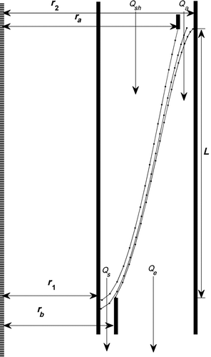
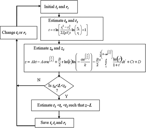
FIG. 2 A flow chart illustrating the iterative procedure used to obtain particle trajectories for a scanning DMA toward determination of its nondiffusive ATF. The different steps in this flow chart are (1) Initialize the particle injection time and location; (2) Calculate the time taken by the particles to reach the inner and outer radii of the sample exit; (3) Determine the axial distance traveled by the particle in the given time; (4) Check if the particle has reached the sample exit over that time; (5) If particle has reached the sample exit, precise residence time is determined and stored, else the above steps are repeated for a different set of initial conditions. Here, z and r are the particle axial and radial locations, respectively; L is the classifier section length; t is the time; and A, B, C, D, α, and k are constants associated with the DMA geometry; and τ is the scan rate. Subscripts i, f, 1, 2, a, b, and r refers to initial, final, inner radii of classifier section, outer radii of classifier section, inner radii of aerosol inlet, outer radii of sample exit and residence time of particles in classifier section, respectively. The full details of the method formulation is provided in CitationDubey and Dhaniyala (2008).
DIFFUSIVE SCANNING DMA ATF
The ATF calculation approach of CitationDubey and Dhaniyala (2008) did not consider the effect of diffusion on particle motion in the classifier section. The diffusional motion of particles in a DMA can be determined from the solution to the set of stochastic differential equations:
To calculate scanning DMA ATFs, the above equations must be solved to determine the times associated with the arrival of particles of a selected mobility at the sample location (i.e., ![]() ). Here, a MC simulation approach, as used previously to obtain fixed-voltage DMA transfer functions (CitationHagwood et al. 1999; Song and Dhaniyala 2006), is used for particle trajectory calculations and for determination of scanning DMA ATFs.
). Here, a MC simulation approach, as used previously to obtain fixed-voltage DMA transfer functions (CitationHagwood et al. 1999; Song and Dhaniyala 2006), is used for particle trajectory calculations and for determination of scanning DMA ATFs.
Monte Carlo Approach
The MC simulations are conducted by injecting particles of a selected mobility at regular time intervals from the inlet of the aerosol flow in the classifier section and tracking their motion over a small time step, Δts , as
The DMA dimensions used for the simulations are inner radii (r 1) of 0.937 cm, outer radii (r 2) of 1.958 cm, and length (L) of 44.44 cm, consistent with the dimensions of the TSI long DMA. A parabolic flow profile is assumed in the classifier section, as in CitationDubey and Dhaniyala (2008). The DMA flows are set as balanced, i.e., the aerosol and sheath flows are equal to the sample and excess flows, respectively. The MC simulations of particle trajectories in the DMA were conducted with 200 singly charged particles injected at 1 ms time interval from 100 different aerosol inlet radial locations. Particles exiting the sample port were counted over a time interval of 50 ms to form the ATF. The approach of CitationDubey and Dhaniyala (2008) is used to obtain mobility-based transfer functions from the calculated ATFs.
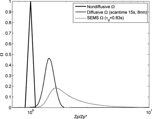
The nondiffusive and diffusive transfer functions obtained from the MC simulations for the DMA operated under fast-scan conditions (scan time of 15 s) are shown in . Also, shown for comparison are the fixed-voltage nondiffusional (CitationKnutson and Whitby 1975) and diffusional transfer functions (CitationStolzenburg 1988). The diffusional scanning DMA transfer functions are obtained from the ATFs calculated for 10 nm particles. The results suggest that the scanning operation has a strong influence in the apparent mean mobility of the sampled particles. This shift in the mean mobility for a scanning operation is because for fast scanning, the particle residence time in the classifier section is comparable to the scan time. The mean mobility shift is seen to be identical for both the diffusional and nondiffusional scanning DMA transfer functions (). A detailed discussion about the mean mobility shift is available in CitationDubey and Dhaniyala (2008). In a scanning DMA, similar to the fixed-voltage case (CitationStolzenburg 1988; CitationHagwood et al. 1999; CitationStolzenburg and McMurry 2008), while diffusion acts to broaden the transfer function relative to the nondiffusional scanning case, the transfer functions area remains the same ().
FIG. 3 Comparison of diffusive and nondiffusive transfer functions for fixed-voltage and scanning operation. The simulation conditions were as follows: sheath flow of 10 lpm, aerosol flow of 1 lpm, and a scan time of 15 s. The particle diameter associated with the transfer function peak was 10 nm. The shift in the apparent mobility is because of the finite particle residence time in the classifier section, relative to the voltage scan time (CitationDubey and Dhaniyala 2008).
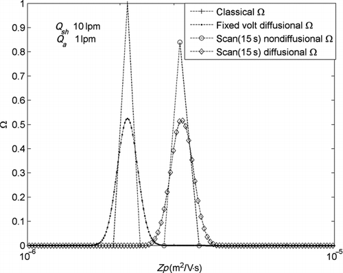
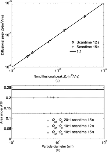
FIG. 4 (a) The peak mobilities of diffusional and nondiffusional scanning DMA transfer functions are identical for all scan times studied. (b) For a scanning DMA, the ATF areas for diffusive particles, obtained from MC simulations, are identical to the ATF areas of the nondiffusive obtained by using the approach of CitationDubey and Dhaniyala (2008). The nondiffusive ATF areas are shown as lines in the figure.
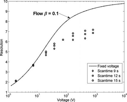
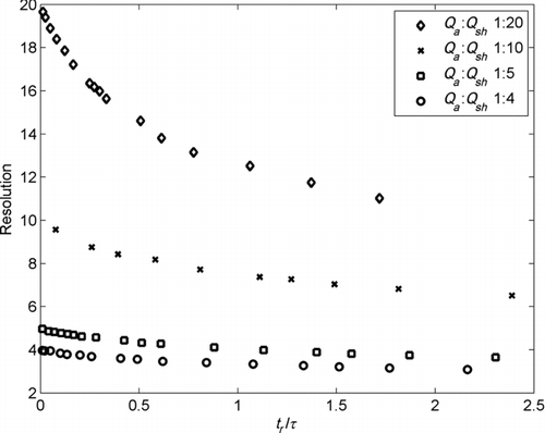
The transfer function resolution, defined as the ratio of the mean mobility sampled to the width of the sampled mobility distribution at half height (CitationZhang and Flagan 1996), as obtained from the MC simulations, is shown in for a range of particle diameters and scan times. Similar to the fixed-voltage case, the scanning DMA resolutions decrease with decreasing voltage. At the high-voltage limit, however, the scanning DMA resolutions do not reach the theoretical limit of CitationKnutson and Whitby (1975), with the maximum resolution attained decreasing with scan time. The reasons for the reduced resolution in the nondiffusional limit under a fast scanning operation have been previously discussed (CitationCollins et al. 2004; CitationDubey and Dhaniyala 2008; CitationMamakos et al. 2008).
FIG. 5 The resolution of scanning DMAs obtained by using MC simulations for a range of scan times.
Direct Approach
The MC simulations suggest that the diffusional particles have a Gaussian-shaped ATF (). The conversion of the linear time-scale ATF to a mobility transfer function in log-scale results in the transformation of the Gaussian-shaped ATF to a lognormal-shaped mobility transfer function. The lognormal approximation of the mobility transfer function for particles in the diffusive regime was shown to be reasonably accurate by CitationStolzenburg and McMurry (2008). Thus, the diffusive ATF Ω(t) can be expressed as follows:
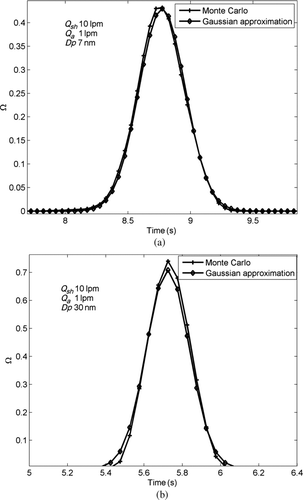
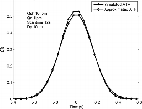
FIG. 6 A comparison of the ATFs obtained from MC simuations and a Gaussian approximation for identical transfer function areas, resolution, and mean location for a scan time of 15 s and particle diameters of (a) 7 nm and (b) 30 nm.
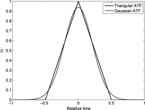
For particles in the nondiffusional regime, the MC simulations confirm that the ATF is triangular shaped, and the ATF can be expressed as follows:
FIG. 7 A comparison of the triangular- and Gaussian-shaped transfer functions for a given area, mean location, and resolution of transfer function.
The ATF for the combined effects of scanning and diffusion can be determined with the knowledge of Area, FWHMFootnote 1 , and the critical peak time, t 2b . To avoid repeated time-consuming MC simulations to calculate scanning DMA transfer functions, the relationship between these parameters and the DMA dimensions and operating conditions must be established. As the peak time (t 2b ) is the same for both the nondiffusional and diffusional transfer functions, the nondiffusional ATF calculation approach of CitationDubey and Dhaniyala (2008) can be used for the determination of this parameter. An efficient method to calculate the Area and FWHM of the transfer functions is introduced here.
ATF FWHM (Δt)
For a mobility transfer function, the FWHM (ΔZp) is related to the transfer function resolution as (CitationZhang and Flagan 1996)
For a triangular ATF, the FWHM (Δt) is calculated as the difference of the times corresponding to the ATF half height (t 2 and t 1, t 1 > t 2). For up-scan voltage operation, it can be shown that (CitationDubey and Dhaniyala 2008)
Expanding the log term in Equation (6) and then using Maclaurin expansion along with the definition for the mean sampled mobility, Equation (6) reduces to
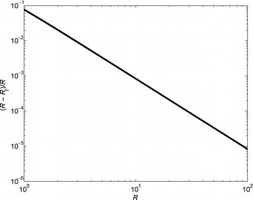
If the resolution of the ATF (Rt ) is defined as the ratio of scan rate, τ, to the time difference at the half height of the ATF (Δt = t 1 − t 2), then from Equations (6) and (8), we get
Thus, the ATF resolution as defined in Equation (9) is consistent with that of CitationZhang and Flagan (1996) for the region where RZp > 1. A comparison of the two resolutions and the difference between them is shown in . This result suggests that the DMA resolutions can be directly determined from an analysis of the calculated ATFs, not requiring the conversion of ATFs to mobility transfer functions.
FIG. 8 The time-based resolution, as defined in Equation (9), is almost identical to the mobility-based resolution defined by CitationZhang and Flagan (1996).
For nondiffusive particles, the calculated transfer function resolutions as a function of the ratio of residence time to the scan rate are shown in . The lowest scan rate considered was ∼ 2.3tr ; scanning at rates faster than this will result in transfer functions varying with mean mobility, as shown in CitationDubey and Dhaniyala (2008). As the scan rate increases, the transfer function resolution for nondiffusive particles decreases significantly. To estimate the effect of diffusion on the resolution of scanning DMA transfer functions, the same analysis can be repeated with diffusive particles.
FIG. 9 The variation in ATF resolution with the ratio of residence time to scan rate for nondiffusive particles.
To minimize the computational expense related to multiple MC simulations, a simpler approach is described here to obtain resolutions of diffusional scanning DMA transfer functions from equivalent fixed-voltage transfer functions. For a fixed-voltage operation, the expression for diffusive transfer function obtained by CitationStolzenburg (1988) can be written as
As demonstrated by CitationFlagan (1999), the DMA transfer function resolution is a function of the aerosol-sheath flow ratio and the applied voltage, but not the total flow. For the dimensions of a TSI long DMA, noting that ![]() , the resolution dependence on aerosol–sheath flow ratio can be reconciled with the introduction of two new variables, a normalized resolution,
, the resolution dependence on aerosol–sheath flow ratio can be reconciled with the introduction of two new variables, a normalized resolution, ![]() , and a normalized voltage,
, and a normalized voltage, ![]() , defined as follows:
, defined as follows:
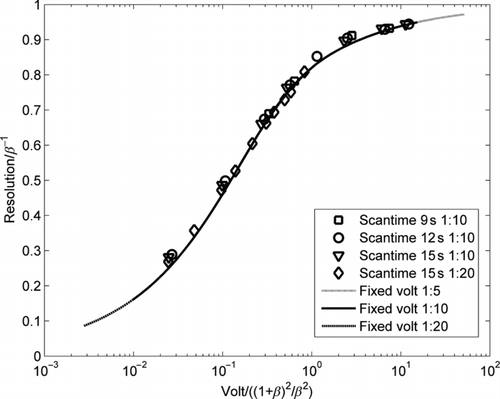
FIG. 10 Using normalized resolution and classification voltage variables, the resolutions of diffusive scanning DMA transfer functions become independent of scan time, and the voltage dependence is identical to that of the fixed-voltage case (CitationStolzenburg 1988).
To compare the resolution of the scanning and the fixed-voltage DMAs by using the above normalized variables, two important considerations are made:
| 1. | For the normalized voltage and resolution [Equation (13)], the value of β is determined as | ||||
| 2. | In the normalized voltage equation, | ||||
The first consideration is made so that the normalized resolution would be 1 in the nondiffusive regime for a scanning operation just as it is for the fixed-voltage case. The second consideration enables the selection of a single voltage corresponding to the mean mobility of the classified particles, from among the continuously varying voltages along the particle trajectory during the scanning operation. With the above considerations, the scanning and fixed-voltage resolution curves are identical (). Thus, the knowledge of the fixed-voltage diffusional transfer function expression (CitationStolzenburg 1988) and the usage of the normalized variables defined in Equation (13) are sufficient to calculate the resolution of the scanning DMA transfer function. From , it is seen that the rate of change of resolution with voltage increases significantly for ![]() less than ∼ 0.8 (corresponding to
less than ∼ 0.8 (corresponding to ![]() ≥ 1). Therefore, for
≥ 1). Therefore, for ![]() ≥ 1, a triangular-shaped ATF is a reasonable assumption. Using this approach, the scanning DMA transfer function resolution and then the FWHM (Δt) (Equation (9)) can be easily determined. The ATF is then obtained by either Equation (3) or Equation (4). A comparison of the transfer functions calculated using this approach with that obtained by using the MC simulations is shown in . The use of the approximate approach with the assumption of a Gaussian shape of the ATF is seen to result in an accurate calculation of diffusive scanning DMA ATF.
≥ 1, a triangular-shaped ATF is a reasonable assumption. Using this approach, the scanning DMA transfer function resolution and then the FWHM (Δt) (Equation (9)) can be easily determined. The ATF is then obtained by either Equation (3) or Equation (4). A comparison of the transfer functions calculated using this approach with that obtained by using the MC simulations is shown in . The use of the approximate approach with the assumption of a Gaussian shape of the ATF is seen to result in an accurate calculation of diffusive scanning DMA ATF.
FIG. 11 A comparison between the ATF obtained by using the MC approach and that obtained assuming a Gaussian distribution with the resolution appropriately determined from .
AREA OF SCANNING DMA TRANSFER FUNCTION
CitationDubey and Dhaniyala (2008) had showed that the area under the transfer function increased with decreasing scan rate. The relative increase in the area under the transfer function was determined to be a function of flow ratio and the ratio of residence time (tr
) to scan rate. It was also demonstrated that for a slow scan, i.e., in the limit of ![]() , the area under the ATF converged to the product of scan rate and flow ratio. The observation was based on just examination of trends in the simulation data. The new definition of ATF resolution, which establishes the equivalence of time and mobility-based resolution (Equation 9), can be used to better understand the previously observed area relationship. For large relative scan times, i.e., for
, the area under the ATF converged to the product of scan rate and flow ratio. The observation was based on just examination of trends in the simulation data. The new definition of ATF resolution, which establishes the equivalence of time and mobility-based resolution (Equation 9), can be used to better understand the previously observed area relationship. For large relative scan times, i.e., for ![]() , and under a balanced flow condition, the area of the triangular ATF (of peak height 1) can be written as
, and under a balanced flow condition, the area of the triangular ATF (of peak height 1) can be written as
Following the observations of CitationDubey and Dhaniyala (2008), the transfer function area can be related to the ratio of residence time to scan rate using a second-order polynomial. Considering the limiting condition of Equation (14), the ATF area can be expressed in terms of the time-based resolution as
To estimate constants k
1,2, several simulations were conducted with the TSI long DMA column dimensions for a wide range of flow ratios ![]() , and the results are shown in . The knowledge of constants k
1,2 and four critical trajectories (three for the vertices of the transfer function and the fourth to estimate the residence time) are sufficient to determine the ATF for the instrument. A comparison of the transfer function obtained by using this approximate approach with one obtained directly from the MC simulations () suggests that approximate method results in very accurate transfer functions calculation. The discrepancy in the approximate transfer function compared with the MC-simulated transfer function was observed to be less than 5%.
, and the results are shown in . The knowledge of constants k
1,2 and four critical trajectories (three for the vertices of the transfer function and the fourth to estimate the residence time) are sufficient to determine the ATF for the instrument. A comparison of the transfer function obtained by using this approximate approach with one obtained directly from the MC simulations () suggests that approximate method results in very accurate transfer functions calculation. The discrepancy in the approximate transfer function compared with the MC-simulated transfer function was observed to be less than 5%.
FIG. 12 The dependence of the values of the constants, k 1,2, associated with the transfer function area calculation, on the DMA flow ratio.
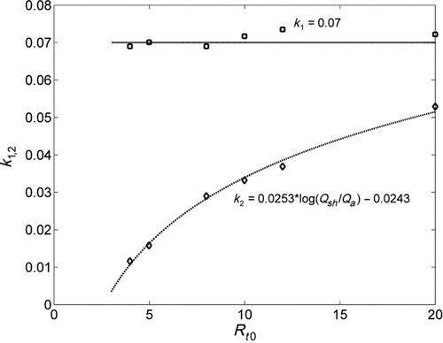
FIG. 13 The ATF obtained by using MC simulations compares well with the one obtained by using the Gaussian approximation, with the resolution and ATF area obtained from and 12.
The effect of diffusion does not change the area under the transfer function, and the variation of area with scan time can be determined by using the approach described above. Thus with the knowledge of the FWHM (Δt), the mean mobility, and the ATF area as a function of scan time, the ATF of a diffusional, scanning DMA can be obtained by Equation (3).
SEMS TRANSFER FUNCTION
In SEMS instruments, particles extracted out of a scanning DMA are typically counted by a single particle counter, such as a CPC. Prior to being counted, the extracted particles transit through a finite tubing length and detector volume, where they are likely to experience mixing. CitationWang and Flagan (1990) accounted for this by just assuming a plumbing delay between the sample exit and the CPC. A more complete treatment of mixing was considered by CitationRussell et al. (1995) who modeled the mixing effect considering a duct with plug flow in series with a Continuously Stirred Tank Reactor. CitationCollins et al. (2002) presented a simpler two-step approach to account for CPC smearing along with the effect of particle diffusion in the DMA classifier section. All of these approaches have helped improve our ability to calculate accurate particle size distributions with SEMS instruments. Here, a simpler and more direct approach to account for the effect of particle smearing between the classifier and the detector on the SEMS particle size distribution calculation is described.
The concept of scanning DMA ATF is extended to introduce a new SEMS transfer function that includes the effects of scanning, diffusion, and downstream smearing. The inclusion of CPC smearing effect in the calculation of the SEMS transfer function will aid in the SEMS problem formulation for the calculation of particle size distributions. With a typical mixing process, particles released instantaneously at the DMA exit will reach the detector over a broad range of times, thus spreading out the arrival times of the particles of a selected mobility. Assuming an exponential decay of particles from the mixing region, the SEMS ATF ![]() can be expressed as
can be expressed as
The entire procedure to obtain SEMS transfer function can be summarized as follows:
| 1. | Determine the critical particle trajectories from the extremum of the aerosol inlet to the extremum of the sample exit by using the equations shown in . From the critical particle trajectories, obtain the residence time and peak voltage (corresponding to peak time) for a given particle diameter (the complete details of this step are given in CitationDubey and Dhaniyala 2008). | ||||
| 2. | Determine the transfer function area by using Equation (15). | ||||
| 3. | For a selected | ||||
| 4. | Determine the applicable shape of the transfer function based on the value of the parameter | ||||
| 5. | Obtain the ATF by using Equations (3) and (4). | ||||
| 6. | Obtain the SEMS ATF by including the effect of smearing by using Equation (16). | ||||
| 7. | Transform the SEMS ATF to a mobility-based SEMS transfer function by using the approach described in CitationDubey and Dhaniyala (2008). | ||||
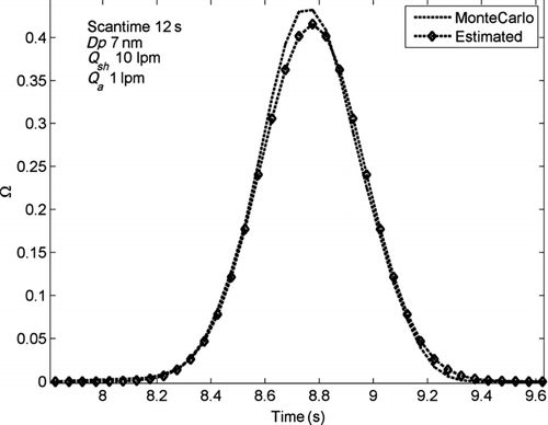
The transfer function of a SEMS system consisting of a TSI long DMA and a CPC with a time constant of 0.83 s, operated under a fast scan rate, is determined using the above approach and is shown in . The downstream smearing acts to shift the mean mobility of the sampled particles and broaden the distribution of mobilities detected at any instant of time. The knowledge of such SEMS transfer functions will permit the direct inversion of SEMS data to obtain particle mobility distributions accounting for the effects of particle diffusion, fast scanning, and detector smearing. Under a fast scan operation and for particles in the diffusional regime, however, the inversion of SEMS data is complicated by the broadening transfer function and the decreasing particle signal per channel. The fastest operation of existing SEMS instruments will, therefore, be limited by the accuracies of the inversion algorithms used and the sensitivity of the available detectors.
FIG. 14 The SEMS transfer function obtained from the time-smeared ATF, considering diffusion, scan rate, and a detector time constant, and compared against the nondiffusive, fixed-voltage DMA transfer function. The SEMS transfer functions were obtained from ATF calculations with 8 nm particle diameters.
CONCLUSION
A new approach to calculate scanning DMA transfer functions, particularly in the diffusional regime, is introduced. Consistent with a fixed-voltage operation, the scanning DMA transfer function can be assumed to be Gaussian in shape in the diffusive regime and triangular otherwise. The knowledge of the area, resolution, and peak location of the ATF enables real-time determination of scanning DMA transfer functions. As scan time decreases, the resolution of the transfer function decreases. Therefore, the use of the classical DMA transfer function under a fast scanning operation will result in erroneous size distribution calculations. For a scanning operation, the scan rate is seen to be the critical determiner of transfer function resolution at the higher classification voltages, while the effect of diffusion is most critical in the low voltage regime. The approach described here allows for fast determination of transfer functions of scanning DMAs and provides a critical step toward size distribution calculations from fast SEMS measurements.
uast_a_579644_sup_18634103.zip
Download Zip (139.5 KB)Acknowledgments
[Supplementary materials are available for this article. Go to the publisher's online edition of Aerosol Science and Technology to view the free supplementary files.]
The authors would like to thank two anonymous reviewers for their critical comments that greatly helped improve the final manuscript. The authors gratefully acknowledge funding support for this research from the National Science Foundation under grant number ATM 0548036. Any opinions, findings, and conclusions or recommendations expressed in this material are those of the authors and do not necessarily reflect the views of the National Science Foundation.
Notes
Note that the FWHM (Δt) of a Gaussian distribution is related to its standard deviation, σ, by a factor of 2.3548.
REFERENCES
- Collins , D. R. , Cocker , D. R. , Flagan , R. C. and Seinfeld , J. H. 2004 . The Scanning DMA Transfer Function . Aerosol Sci. Technol. , 38 : 833 – 850 .
- Collins , D. R. , Flagan , R. C. and Seinfeld , J. H. 2002 . Improved Inversion of Scanning DMA Data . Aerosol Sci. Technol. , 36 : 1 – 9 .
- Dubey , P. and Dhaniyala , S. 2008 . Analysis of Scanning DMA Transfer Function . Aerosol Sci. Technol. , 42 : 544 – 555 .
- Flagan , R. C. 1999 . On Differential Mobility Analyzer Resolution . Aerosol Sci. Technol. , 30 : 556 – 570 .
- Hagwood , C. , Sivathanu , Y. and Mulholland , G. 1999 . The DMA Transfer Function with Brownian Motion a Trajectory/Monte-Carlo Approach . Aerosol Sci. Technol. , 30 : 40 – 61 .
- Knutson , E. O. and Whitby , K. T. 1975 . Aerosol Classification by Electrical Mobility: Apparatus Theory and Applications . J. Aerosol Sci. , 6 : 443 – 451 .
- Mamakos , A. , Ntziachristos , L. and Samaras , Z. 2008 . Differential Mobility Analyzer Transfer Functions in Scanning Mode . J. Aerosol Sci. , 39 : 227 – 243 .
- Park , K. , Dutcher , D. , Emery , M. , Pagels , J. , Sakurai , H. , Scheckman , J. , Qian , S. , Stolzenburg , M. R. , Wang , X. , Yang , J. and McMurry , P. H. 2008 . Tandem Measurements of Aerosol Properties—A Review of Mobility Techniques with Extensions . Aerosol Sci. Technol. , 42 : 801 – 816 .
- Russell , L. M. , Flagan , R. C. and Seinfeld , J. H. 1995 . Asymmetric Instrument Response Resulting from Mixing Effects in Accelerated DMA–CPC Measurements . Aerosol Sci. Technol. , 23 : 491 – 509 .
- Song , D. K. and Dhaniyala , S. 2007 . Change in Distributions of Particle Position by Brownian Diffusion in a Non-Uniform External Field . J. Aerosol Sci. , 38 : 444 – 454 .
- Stolzenburg , M. R. 1988 . “ An Ultrafine Aerosol Size Distribution Measuring System. Ph.D. thesis ” . Minneapolis , MN : University of Minnesota .
- Stolzenburg , M. R. and McMurry , P. H. 2008 . Equations Governing Single and Tandem DMA Configurations and a New Lognormal Approximation to the Transfer Function . Aerosol Sci. Technol. , 42 : 421 – 432 .
- Wang , S. C. and Flagan , R. C. 1990 . Scanning Electrical Mobility Spectrometer . Aerosol Sci. Technol. , 13 : 230 – 240 .
- Zhang , S. H. and Flagan , R. C. 1996 . Resolution of the Radial Differential Mobility Analyzer for Ultrafine Particles . J. Aerosol Sci. , 27 : 1179 – 1200 .