Abstract
Electrostatic spray deposition is an innovative coating technique that produces fine, uniform, self-dispersive (due to Coulombic repulsion), and highly wettable, atomized droplets. Copper–indium salts are dissolved in an alcohol-based solvent; this precursor is then electrostatically sprayed onto a moderately heated, molybdenum-coated substrate. Precursor flowrates range from 0.02 to 5 mL/h under applied voltages of 1–18 kV, yielding droplet sizes around a few hundred nanometers. Comparing scanning electron microscope images of the coated samples showed that the substrate temperature, applied voltage, and precursor flowrate were the primary parameters controlling coating quality. Also, the most stable electrostatic spray mode that reliably produced uniform and fine droplets was the cone-jet mode with a Taylor cone issuing from the nozzle.
INTRODUCTION
For the past few decades, copper, indium, and selenium (CIS)-based thin films have attracted attention in the photovoltaic industry because of: (1) minimized material consumption, (2) low-cost substrate availability (e.g., soda-lime glass, stainless steel, foil, and polymers), (3) availability of flexible, light, strong, and thin substrates that are resistant to degradation by solar radiation and severe environments, (4) favorable optical and electrical properties such as tunable band gaps from 1 to 2.4 eV through addition of gallium (Ga) and sulfur (S) that capture shorter light wavelengths, (5) large photon absorption coefficients, and (6) high power-conversion efficiencies of 15–20% (Romeo et al. Citation2004). However, advances in CIS-based solar cells have been hampered by high manufacturing costs and the capital and energy requirements of conventional vacuum deposition methods (e.g., coevaporation and sputtering). Non-vacuum-based deposition methods would greatly reduce costs and enhance solar-energy-technology market penetration. Competitive energy cost of $1/watt could be realized if solar cell efficiencies were to exceed 6% using non-vacuum methods (Zweibel Citation1999; Kaelin et al. Citation2004).
Non-vacuum methods include spin-coating, electrodeposition, screen-printing, doctor-blading, paste-coating, printing-precursor, and spray pyrolysis (Mitzi et al. Citation2008). Mitzi et al. (2004, 2006, 2008) and Milliron et al. (Citation2006) used non-vacuum spin coating to deposit a Cu–In–Ga–Se (CIGS) precursor (using a hydrazine solvent) and achieved a power conversion efficiency of 10.3%. Such efficiency was possible because hydrazine dissolves binary chalcogenides, such as Cu–S, In–Se, Ga–Se, without any additives; hence, it precludes impurities such as carbon and oxygen that increase the resistance of the film and hinder solar cell performance (Mitzi et al. Citation2008, Citation2009). However, the reactivity and toxicity of hydrazine limit its widespread use. Ahn et al. (Citation2010) coated a substrate with Cu–In–Ga solutions (i.e., Cu(NO3)2 InCl3, Ga(NO3)3, which are nontoxic, relatively safe, and inexpensive) using the doctor-blading technique, but achieved a low efficiency of 2% because of impurities, especially from the ethyl cellulose solvent, which is a highly viscous additive required for spreading of the precursor without dripping. In addition to the spin-coating and doctor-blading techniques, spray pyrolysis (SP), or aerosol-driven deposition, is a promising, low-cost deposition technique because of its ability to cover larger substrate areas (Gorska et al. Citation1979). As an example, Modesto-Lopez and Biswas (Citation2010) used aerosol-chemical vapor deposition to deposit nanostructured titanium dioxide (TiO2) and nickel oxide (NiO) films onto an indium tin oxide (ITO) substrate for solar cell applications.
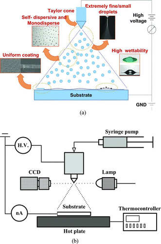
In SP, a solvent suspends CIGS nanoparticles (a particle-based method, PBM). On the other hand, when the solvent is a 100% solution (without particles) that completely dissolves the CI, CIS, or CIGS components, it is a solution-based method (SBM). Whether SP is a PBM or SBM, its inherent disadvantage is its porous coating due to incomplete cohesion of the deposited powder (whether it is the nanoparticles in PBM or salt residues of the evaporated solvent in SBM). This shortcoming of conventional SP can be circumvented using an electrostatic spray, which produces extremely fine (submicrometer), self-dispersive (nonagglomerating), highly wettable (electrowetting), and adhesive droplets to yield a uniform coating on the substrate (see ). In addition, because charged droplets are accelerated toward the substrate, targeting is improved resulting in high electrostatic spray deposition (ESD) efficiency.
FIG. 1 (a) Advantages of the electrostatic spray deposition. (b) Experimental setup of the ESD system. (Color figure available online.)
Lu et al. (Citation2003) coated a perovskite (1,0,0)-oriented lead–zirconate–titanate precursor with ESD to yield 2-μm thin films with excellent electrical properties (e.g., suitable ferroelectrics and no current leakage, based on polarization-electric field hysteresis loop results). Kaelin et al. (Citation2004) used Cu–In nanoparticles (100 nm average diameter using a PBM) suspended in ethanol and 1,2-propanediol carriers to apply a CIS thin film that was subsequently augmented with a selenization process to make a CIS film. They concluded that ESD provides improved surface morphology over the doctor-blading and the screen-printing techniques. ESD TiO2-based solar cells have been extensively studied by Hogan and Biswas (Citation2008) and Modesto-Lopez and Biswas (Citation2010); however, Kaelin et al. (Citation2004) noted that ESD may not be suitable if the precursor's conductivity is high thereby destabilizing the cone-jet at the nozzle tip. To avoid this destabilization, more viscous solvents could be used.
Despite ESD's potential, operations governing its effectiveness and morphological suitability for deposition of Cu–In thin films have not been outlined (Kaelin et al. Citation2004). Submicrometer droplets can only be produced by a stable Taylor cone-jet (Gañán-Calvo Citation1997), which requires exacting knowledge of the voltage level and electrical current requirements. This knowledge is difficult to obtain because the electrical current strongly depends on solvent conductivity, which, in turn, varies significantly with the Cu–In ion concentration.
To study cone-jet stability of a solvent containing Cu–In ions, we have, for the first time, quantitatively measured the ranges of both voltage and electrical current that yield a stable Taylor cone-jet. Furthermore, the scaling laws that estimate the size of the atomized droplets at the tip of the Taylor cone-jet due to Rayleigh explosion are briefly covered (Ganan-Calvo 1994; Tang and Gomez Citation1994; Chen and Pui Citation1997; Duft et al. Citation2003). A micrometer-thick Cu–In thin film is developed by depositing atomized droplets onto heated, molybdenum (Mo)-coated soda-lime glass. The effect of substrate temperature on surface morphology is also investigated.
EXPERIMENTAL SETUP
This work determines the ranges of voltage and current that yield stable Taylor cone-jets for Cu–In precursors using various solvents. Moreover, the thin-film characteristics (i.e., surface morphology and X-ray diffraction (XRD) spectra of Cu–In electrostatically spray-deposited onto a heated Mo substrate) are examined.
Inexpensive and nontoxic Cu–In salts are dissolved in alcohol-based solvents; all preparations are formulated at room temperature in air. The working fluids (solvents) are pure ethanol and butyl-carbitol. Copper nitrate hydrate (Cu(NO3)2·3H2O; 99.999%) and indium chloride (InCl3; 99.999%) were purchased from Sigma Aldrich, and butyl-carbitol (C4H9(OCH2CH2)2OH; 99.0%) from Duksan Chemical. The thermofluid properties of the solvents are listed in . It should be noted that the precursors remain fairly conductive because of the high electrical conductivity of Cu–In ions. The Cu–In precursor is electrostatically sprayed onto a heated (290–373 K) Mo substrate to undergo pyrolysis and form a thin film.
TABLE 1 Solvent physic-chemical properties
While organometallic-based precursors might have yielded better quality films, their toxicity and cost preclude them from use in low-cost solar cells (Mitzi et al. Citation2008). Also, postannealing selenization was not undertaken in this effort because it was felt that it was not relevant to the study of voltages and currents that yield stable precursor ESD flows.
For both ethanol- and butyl-carbitol-based solvents, the component ratio of Cu:In is 9:10. This copper-poor precursor is preferred because its chalcopyrite grain structure has (1,1,2) orientation (Shay et al. Citation1975; Bates et al. Citation1982; Mooney and Radding Citation1982; Abernathy et al. Citation1984; Bougnot et al. Citation1986; Mooney and Lamoreaux Citation1986).
The ESD system setup is shown in . The downward-facing nozzle center is aligned with the plate center separated by a 45 mm gap with a cone angle of 40°, which deposits the precursors onto an area of 25 × 25 mm2 on the Mo substrate. Molybdenum substrates provide the best back-contact (or electrode) performance because of their superior electrical conductivity and interfacial adhesion between the CIGS absorber layer and the electrode (Dhere and Dhere Citation2005). An ITO or fluorine tin oxide (FTO) substrate could have been used, but these have shown poorer performance for CIGS solar cells (Romeo et al. Citation2004). Furthermore, ITO and FTO do not withstand the high temperature requirements of the postannealing selenization process.
The precursor issues from a syringe pump with flowrate adjusted to yield a stable Taylor cone-jet, which produces the smallest droplets possible under the given operating conditions. The nozzle inner diameter is 3 mm. A voltage-supply wire is attached to the charging needle (i.e., anode) and the substrate is grounded (i.e., cathode). Typically, it takes 10–15 min to yield a CIGS film of 1–2-μm thickness. The deposition efficiency (ratio of deposited to sprayed volume) is 9–13%. Because the substrate temperature is higher than the solvent's boiling point, it is inferred that the deposited film comprises mainly copper and indium. Under this assumption, the deposition efficiency of the copper and indium is 80–90% based on a 10% Cu–In volume concentration in the solvent.
RESULTS AND DISCUSSION
Spray Modes
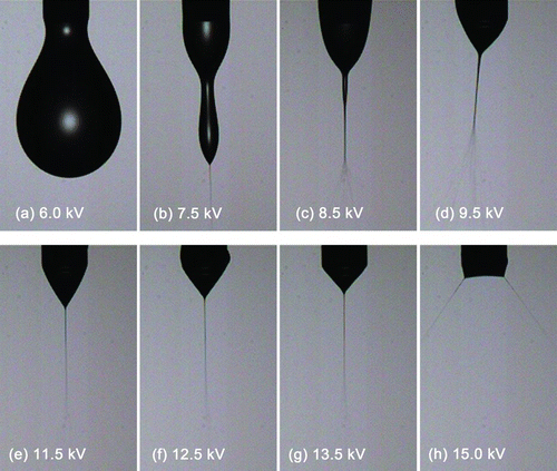
shows the various electrostatic spray modes at a flowrate of 1 mL/h. At a low voltage of 6 kV, single droplets are formed as governed by any axial vibration (or disturbance). At a voltage of 7.5 kV, a spindle mode is observed; at the tip of the spindle, a microjet is formed that produces small liquid droplets. Increased voltage induces a highly oscillatory (or unstable) mode. At around 11.5 kV, the cone-jet appears, but it is elongated because there is insufficient charge (or voltage) to overcome the cohesive surface tension forces that tend to deflect the spray. When sufficient charge is supplied (12.5 and 13.5 kV), the cone is fully developed, showing reduced effect from surface tension. When the cone is excessively charged (>15 kV), it breaks up into multiple jets because accumulated charges have reached the limit and these charges have to be redistributed across the larger surface area of the multiple jets. The relationship between current and flowrate using the scaling law of Gañán-Calvo et al. (1994) is:
where κ is the dielectric constant (or relative permittivity), γ is the surface tension, K is the liquid electrical conductivity, and Q is the flow rate. As described above, three modes are observed: spindle, cone-jet, and the multijet modes (in the order of increasing voltage). A hysteresis is evident in as the multijet mode begins at about 16.8 kV when the voltage is increasing; with decreasing voltage, the multijet mode persists down to 15 kV.
FIG. 2 Shape variation of the electrostatic spray for increasing charge levels (voltages): (a) dripping mode, (b), (c) spindle mode, (d) oscillating mode, (e)–(g) cone-jet modes; elongated, moderately shaped and tightly shaped and (h) multijet mode. (Color figure available online.)
shows the maximum and minimum flowrates (or currents) with respect to voltage for two precursors (the triangles, ▴ & ▵, for ethanol and squares, ▪ & □, for butyl-carbitol). Currents above the maximum line (filled symbols) or below the minimum line (hollow symbols) yield destabilized cone-jets. Toward the maximum flowrate (i.e., the filled symbols), the cone-jet is elongated because of the high mass-flowrate-to-charge ratio. If mass flowrates are further increased, the cone-jet passes back through the oscillating and spindle modes before ending up in the dripping mode. Conversely, if the flowrate-per-unit-voltage is low, the liquid charge density increases, and multijets are produced by the excessive charge.
FIG. 3 Typical current versus voltage curves showing hysteresis for the cone-jet and multijet modes.
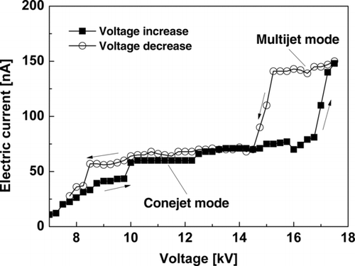
FIG. 4 Typical current versus voltage curves that correspond to the minimum and maximum flowrate with respect to voltage for two solvents (ethanol and butyl-carbitol) with Cu–In. Any regime outside the maximum and minimum curves is unstable.
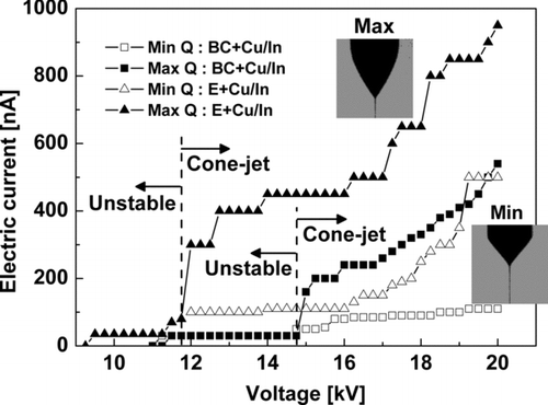
It is interesting to compare the Taylor cone-jet flowrate (or current) ranges of the ethanol and butyl-carbitol precursors. The ethanol precursor supports higher stable flowrates than the butyl-carbitol. A precursor's high conductivity prevents a jet from achieving high mass flowrates; compare the typical mass flowrates of pure ethanol and the ethanol solvent containing Cu–In in . Highly conducting fluids have ions at the cone surface that weaken surface tension (curvature) forces, resulting in thinner cone jets that prevent the precursor from efficient jetting; this is because of the constant value of κ 1/2 γϵ0 /ρ ∼ Q min K (Chen et al. Citation1995; Lastow and Balachandran Citation2007). Basak et al. (Citation2007) developed scaling laws for particle diameters produced by drying droplets from electrospraying ionic precursors. They noted that the flowrate for the strong Fe(NO3)3 ionic (or electrolyte) precursor is 20–24 times less than the flowrate for the weak electrolyte. While it is evident that conductivity has a profound effect on mass flowrate, conductivity alone does not explain the higher allowable mass flowrate of the ethanol or/and butyl-carbitol solvents; the effect of viscosity on flowrate must be considered.
According to Rosell-Llompart and Fernandez de La Mora (1994), if a liquid's viscosity increases, the droplet size also increases. They also concluded that the cone-jet structure and the current passed by the jet strongly depend on dimensionless parameters, κ, η, and Π μ . Rosell-Llompart and Fernandez de La Mora (1994) suggested an inverse measure of the dimensionless viscosity parameter, Π μ , as
TABLE 2 Previous studies on morphology of sprayed Cu–In thin films
It is also known that the dielectric constant plays an important role in determining the mass flowrate (Chen and Pui Citation1997). The dimensionless flowrate, η, is defined as
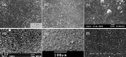
FIG. 5 Top views of CuInSe2 or CuInS2 films deposited with various spray techniques. (a) CuInSe2 film at 290°C for Cu/In = 1.0 by Bougnot et al. (Citation1986), (b) CuInS2 film at 277°C for Cu/In = 0.94 by Subbaramaiah and Raja (Citation1991), (c) CuInSe2 film at 300°C for Cu/In = 1.0 by Shirakata et al. (Citation1996), (d) CuInS2 film at 380°C for Cu/In = 1.0 by Krunks et al. (Citation1999), (e) CuInSe2 film at 90°C for Cu/In = 1.0 by Kaelin et al. (Citation2004), (f) CuIn film at 97°C for Cu/In = 0.9 by Yoon et al. (current experiment). Reprinted under permission of Elsevier.
Deposited Film Morphology
Morphologies of sprayed Cu–In thin films have been studied by various authors (Bougnot et al. Citation1986; Subbaramaiah and Raja Citation1991; Shirakata et al. Citation1996; Krunks et al. Citation1999; Eberspacher et al. Citation2001; Kaelin et al. Citation2004; Lee and Kim Citation2011); their studies are summarized in .
Their precursors containing either CuInSe2 or CuInS2 were sprayed onto various substrates (i.e., pyrex, glass, stainless steel, Mo-coated glass). Chemical pyrolysis occurs for a substrate temperature range of 90–500°C. Postannealing (such as postselenization, postsulfurization, sintering, etc.) crystallizes the deposited layer, removes voids, and vaporizes impurities. Although postannealing is typically undertaken, it is not necessary if the polycrystalline structure of the absorber layer produced without postannealing is satisfactory. The film morphology of this study as well as those from most of the aforementioned studies do not include the postannealing process. In general, the higher the substrate temperature, the more complete the crystallization and therefore the larger the grain size.
compares the morphologies (top-views) of CuInSe2 or CuInS2 films deposited by various spray methods (e.g., pneumatic or electrostatic). The Cu–In ratios are in the range of 0.9 ≤ Cu/In ≤ 1.0. Experiments in –d were pneumatically sprayed using nitrogen as the carrier gas; substrate temperatures (T s) were relatively high in the range of 277°C ≤ T s ≤ 380°C. The thin films from and f were deposited by electrostatic spray at relatively low substrate temperatures (90°C ≤ T s ≤ 97°C). The surface morphology, crystallization, and grain size of the electrosprayed surfaces could have been denser and larger if the substrate temperatures had been higher than 97°C. Nevertheless, the surface morphology from the electrostatic sprays is comparable to other films created with pneumatic sprays. It is also clear that the surface morphology of the current experiment () is more uniform than the one () by Kaelin et al. (Citation2004).
compares thin-film morphologies at various substrate (molybdenum-coated soda-lime glass via sputtering) temperatures. At 17°C, atomized droplets stick to the substrate and coalesce to form dark lumps due to slow solvent evaporation by natural convection. These lumps are surrounded by white residues of noncrystallized Cu–In precursors. These residues are not crystallized because of the lack of heat required for pyrolysis.
Upon increasing the substrate temperature (approaching the boiling point of ethanol at 78°C), the dark lumps diminish and white crystals become more apparent (). At a substrate temperature of 97°C (), the film is well-crystallized and the thin-film coating is successful. However, when using ethanol as a solvent, stability issues remain. Increased conductivity due to dissolved Cu–In salts substantially destabilizes the cone-jet surface, despite the competing stabilizing forces of surface tension and viscosity. This yields a delicate balance and minor external disturbances result in a destabilized jet every 3–4 min. The film thickness in is about 0.1-μm (side view not shown), but an approximately 1-μm-thick film is needed for an appropriate CIS absorber layer, which would require 30–40 min of continuous spraying. This is not possible when using ethanol as the solvent because of the jet instability mentioned above.
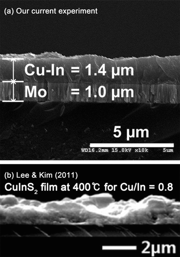
Fortunately, butyl-carbitol provides a good balance of volatility, solvency, water solubility, and jet stability (because of its relatively high viscosity and surface tension). Although the flowrate of the butyl-carbitol solvent is lower than ethanol because of its high viscosity and dielectric constant, the allowable Cu–In concentrations are higher than those for ethanol, so that 30 min of spraying deposits 1−6-μm of film (depending on the operating conditions and precursor preparation). With a boiling temperature for butyl-carbitol of 231°C, the substrate temperature should be set to 300°C to allow sufficient supply of heat for rapid evaporation and pyrolysis of the droplets. is the cross-sectional view of a 1.4-μm-thick electrosprayed Cu–In film on a 1-μm-thick molybdenum substrate while shows the cross-sectional view of the ultrasonic-sprayed CuInS2 film of Lee and Kim (Citation2011). Both films are dense and free of voids. In a solar cell, compact films transmit electrons efficiently, which yield high electrical currents and high voltages. Note that the film produced by electrostatic spray is flatter and more uniform than the one produced by ultrasonic spray.
FIG. 6 Deposition of an ethanol solvent with dissolved Cu–In salts onto a Mo-coated substrate at different substrate temperatures.
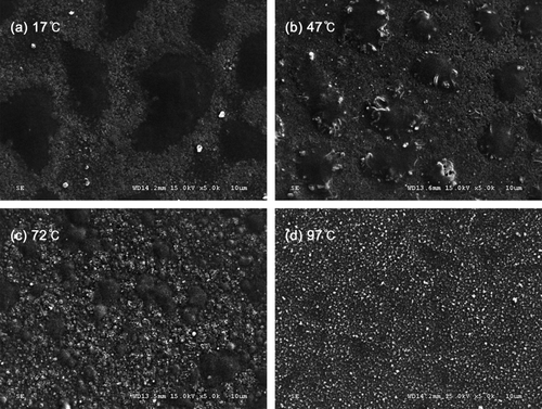
FIG. 7 Cu–In thin film of 1.4-μm thickness on an Mo substrate. is reprinted under permission of Elsevier.
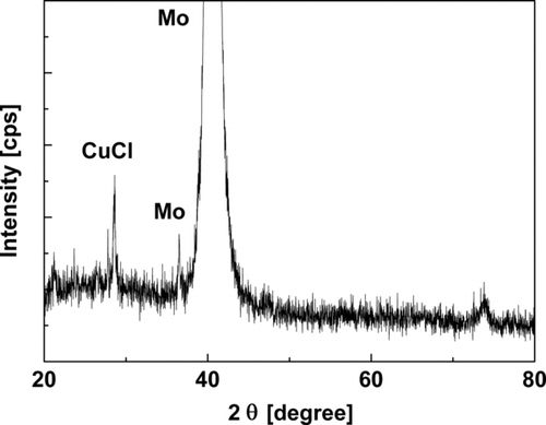
is an XRD image of the film shown in . Copper is found in the form of CuCl (Cu+) in the precursor film. This may seem peculiar because Cu(NO3)2 was sprayed (Cu2+), but Cu2+ was reduced to Cu+ by accepting an electron from a reducing agent in the solvent mixture, most likely butyl-carbitol, which reduces certain metallic ions. The energy-dispersive X-ray spectroscopy (EDS) analysis showed that the atomic ratio of Cu/In varied from 0.8 to 1.0; the presence of indium is confirmed although not shown in the XRD result. Because it exists in an amorphous state in the precursor film, indium has not been lost during the coating processes (Ahn et al. Citation2010). The chlorine content in the film is not of a significant issue because the postselenization would vaporize Cl2 and would preclude its inclusion in the film. In general, the Cl2 is not detectable by the energy-dispersive spectrometer after the postselenization process.
CONCLUSION
An ESD technique can apply Cu–In thin films for solar cell applications. Stable Taylor cone-jets electrostatically deposit submicrometer-sized droplets. The ranges of voltage and electrical current that yield stable ESD cone-jets are provided. The substrate temperature should always be higher than the boiling point of the working fluid for rapid evaporation and crystallization of the precursors. Butyl-carbitol yields a stable cone-jet because of its relatively high viscosity and surface tension, making it a candidate working fluid (solvent). Considering that the Cu–In film deposited by ESD is denser and flatter than those of Krunks et al. (1999; 2000) and Ahn et al. (Citation2010), who also used CuCl2 and InCl3 aqueous solution precursors, the realization of low-cost, high-efficiency, thin-film solar cells is one step closer.
Acknowledgments
This research was supported by the Research Center of Break-through Technology Program through the Korea Institute of Energy Technology Evaluation and Planning (KETEP) funded by the Ministry of Knowledge Economy (2009-3021010030-11-1) and by the Korea Research Council Industrial Science and Technology (B551179-08-03-00).
This work was partly supported by the Center for Inorganic Photovoltaic Materials (NRF-2011-0007182) funded by the Korean government (MEST).
REFERENCES
- Abernathy , C. , Bates , C. Jr. , Anani , A. , Haba , B. and Smestad , G. 1984 . Production of Single Phase Chalcopyrite CuInSe by Spray Pyrolysis . Appl. Phys. Lett. , 45 : 890 – 892 .
- Ahn , S. , Kim , C. , Yun , J. H. , Gwak , J. , Jeong , S. , Ryu , B.-H. and Yoon , K. 2010 . CuInSe2 (CIS) Thin Film Solar Cells by Direct Coating and Selenization of Solution Precursors . J. Phys. Chem. C , 114 : 8108 – 8113 .
- Basak , S. , Chen , D.-R. and Biswas , P. 2007 . Electrospray of Ionic Precursor Solutions to Synthesize Iron Oxide Nanoparticles: Modified Scaling Law . Chem. Eng. Sci. , 62 : 1263 – 1268 .
- Bates , C. Jr. , Nelson , K. , Atiq Raza , S. , Mooney , J. , Recktenwald , J. , Macintosh , L. and Lamoreaux , R. 1982 . Spray Pyrolysis and Heat Treatment of CuInSe2 for Photovoltaic Applications . Thin Solid Films , 88 : 279 – 283 .
- Bougnot , J. , Duchemin , S. and Savelli , M. 1986 . Chemical Spray Pyrolysis of CuInSe2 Thin Films . Solar Cells , 16 : 221 – 236 .
- Chen , D.-R. and Pui , D. Y. H. 1997 . Experimental Investigation of Scaling Laws for Electrospraying: Dielectric Constant Effect . Aerosol Sci. Technol. , 27 : 367 – 380 .
- Chen , D.-R. , Pui , D. Y. H. and Kaufman , S. L. 1995 . Electrospraying of Conducting Liquids for Monodisperse Aerosol Generation in the 4 nm to 1.8 μm Diameter Range . J. Aerosol Sci. , 26 : 963 – 977 .
- Dhere , N. G. and Dhere , R. G. 2005 . Thin-Film Photovoltaics . J. Vac. Sci. Technol. A: Vac. Surf. Films , 23 : 1208
- Duft , D. , Achtzehn , T. , Muller , R. , Huber , B. and Leisner , T. 2003 . Coulomb Fission: Rayleigh Jets from Levitated Microdroplets . Nature, , 421 : 128
- Eberspacher , C. , Fredric , C. , Pauls , K. and Serra , J. 2001 . Thin-Film CIS Alloy PV Materials Fabricated Using Non-Vacuum, Particles-Based Techniques . Thin Solid Films , 387 : 18 – 22 .
- Gañán-Calvo , A. 1994 . The Size and Charge of Droplets in the Electrospraying of Polar Liquids in Cone-Jet Mode, and the Minimum Droplet Size . J. Aerosol Sci. , 25 : 309 – 310 .
- Gañán-Calvo , A. M. 1997 . Cone-Jet Analytical Extension of Taylor's Electrostatic Solution and the Asymptotic Universal Scaling Laws in Electrospraying . Phys. Rev. Lett. , 79 : 217 – 220 .
- Gañán-Calvo , A. M. , Dávila , J. and Barrero , A. 1997 . Current and Droplet Size in the Electrospraying of Liquids. Scaling Laws . J. Aerosol Sci. , 28 : 249 – 275 .
- Gañán-Calvo , A. M. , Lasheras , J. C. , Dávila , J. and Barrero , A. 1994 . The Electrostatic Spray Emitted from an Electrified Conical Meniscus . J. Aerosol Sci. , 25 : 1121 – 1142 .
- Gorska , M. , Beaulieu , R. , Loferski , J. J. and Roessler , B. 1979 . CuInS2 Films Prepared by Spray Pyrolysis . Sol. Energy Mater. , 1 : 313 – 317 .
- Hogan , C. J. and Biswas , P. 2008 . Porous Film Deposition by Electrohydrodynamic Atomization of Nanoparticle Sols . Aerosol Sci. Technol. , 42 : 75 – 85 .
- Kaelin , M. , Zogg , H. , Tiwari , A. N. , Wilhelm , O. , Pratsinis , S. E. , Meyer , T. and Meyer , A. 2004 . Electrosprayed and Selenized Cu/In Metal Particle Films . Thin Solid Films, , 457 : 391 – 396 .
- Krunks , M. , Bijakina , O. , Varema , T. , Mikli , V. and Mellikov , E. 1999 . Structural and Optical Properties of Sprayed CuInS2 Films . Thin Solid Films, , 338 : 125 – 130 .
- Krunks , M. , Mikli , V. , Bijakina , O. , Rebane , H. , Mere , A. , Varema , T. and Mellikov , E. 2000 . Composition and Structure of CuInS2 Films Prepared by Spray Pyrolysis . Thin Solid Films, , 361–362 : 61 – 64 .
- Lastow , O. and Balachandran , W. 2007 . Novel Low Voltage EHD Spray Nozzle for Atomization of Water in the Cone Jet Mode . J. Electrostat. , 65 : 490 – 499 .
- Lee , D.-Y. and Kim , J. 2011 . Deposition of CuInS2 Films by Electrostatic Field Assisted Ultrasonic Spray Pyrolysis . Sol. Energy Mater. Sol. Cell. , 95 : 245 – 249 .
- Lu , J. , Chu , J. , Huang , W. and Ping , Z. 2003 . Microstructure and Electrical Properties of Pb (Zr, Ti) O3 Thick Film Prepared by Electrostatic Spray Deposition . Sens. Actuators, A , 108 : 2 – 6 .
- Milliron , D. , Mitzi , D. , Copel , M. and Murray , C. 2006 . Solution-Processed Metal Chalcogenide Films for P-Type Transistors . Chem. Mater. , 18 : 587 – 590 .
- Mitzi , D. , Copel , M. and Murray , C. 2006 . High-Mobility P-Type Transistor Based on a Spin-Coated Metal Telluride Semiconductor . Adv. Mater. , 18 : 2448 – 2452 .
- Mitzi , D. , Kosbar , L. , Murray , C. , Copel , M. and Afzali , A. 2004 . High-Mobility Ultrathin Semiconducting Films Prepared by Spin Coating . Nature , 428 : 299 – 303 .
- Mitzi , D. , Yuan , M. , Liu , W. , Kellock , A. , Chey , S. , Deline , V. and Schrott , A. 2008 . A High-Efficiency Solution-Deposited Thin-Film Photovoltaic Device . Adv. Mater. , 20 : 3657 – 3662 .
- Mitzi , D. , Yuan , M. , Liu , W. , Kellock , A. , Chey , S. , Gignac , L. and Schrott , A. 2009 . Hydrazine-Based Deposition Route for Device-Quality CIGS Films . Thin Solid Films , 517 : 2158 – 2162 .
- Modesto-Lopez , L. B. and Biswas , P. 2010 . Role of the Effective Electrical Conductivity of Nanosuspensions in the Generation of TiO2 Agglomerates with Electrospray . J. Aerosol Sci. , 41 : 790 – 804 .
- Mooney , J. and Lamoreaux , R. 1986 . Spray Pyrolysis of CuInSe2 . Solar Cells , 16 : 211 – 220 .
- Mooney , J. and Radding , S. 1982 . Spray Pyrolysis Processing . Annu. Rev. Mater. Sci. , 12 : 81 – 101 .
- Romeo , A. , Terheggen , M. , Abou-Ras , D. , Bätzner , D. L. , Haug , F. J. , Kälin , M. , Rudmann , D. and Tiwari , A. N. 2004 . Development of Thin-Film Cu(In,Ga)Se2 and CdTe Solar Cells . Prog. Photovoltaics Res. Appl. , 12 : 93 – 111 .
- Rosell-Llompart , J. and Fernandez de la Mora , J. 1994 . Generation of Monodisperse Droplets 0.3 to 4 μm in Diameter from Electrified Cone-Jets of Highly Conducting and Viscous Liquids . J. Aerosol Sci. , 25 : 1093 – 1119 .
- Shay , J. , Wagner , S. and Kasper , H. 1975 . Efficient CuInSe2/CdS Solar Cells . Appl. Phys. Lett. , 27 : 89 – 90 .
- Shirakata , S. , Murakami , T. , Kariya , T. and Isomura , S. 1996 . Preparation of CuInSe2 Thin Films by Chemical Spray Pyrolysis . Japan Soc. Appl. Phys. , 35 : 191 – 199 .
- Subbaramaiah , K. and Raja , V. 1991 . Effect of Substrate Temperature on the Properties of Spray-Deposited CuInS2 Thin Films . Mater. Lett. , 12 : 67 – 71 .
- Tang , K. and Gomez , A. 1994 . Generation by Electrospray of Monodisperse Water Droplets for Targeted Drug Delivery by Inhalation . J. Aerosol Sci. , 25 : 1237 – 1249 .
- Zweibel , K. 1999 . Issues in Thin Film PV Manufacturing Cost Reduction . Sol. Energy Mater. Sol. Cell. , 59 : 1 – 18 .
