Abstract
Cooled exhaust gas recirculation (EGR) is widely used in diesel engines to control engine out NOx (oxides of nitrogen) emissions. A portion of the exhaust gases is recirculated into the intake manifold of the engine after cooling it through a heat exchanger. EGR cooler heat exchangers, however, tend to lose efficiency and have increased pressure drop as deposit forms on the heat exchanger surface. This adversely affects the combustion process, engine durability, and emissions. In this study, a 1-D model was developed to simulate soot deposition, soot removal, and condensation of several hydrocarbon (HC) species in a circular tube with turbulent gas flow at constant wall temperature. The circular tube, which makes up the computational domain in the model, represents a single channel from any EGR cooler geometry. The model takes into account soot particle deposition due to thermophoresis, diffusion, turbulent impaction, and gravitational drift. However, thermophoresis was found to be the most dominant deposition mechanism for boundary conditions at which EGR coolers typically operate. Soot removal was modeled by considering a force balance between the drag and van der Waals forces. A lognormal distribution of particles was assumed at the tube inlet. The evolution of the particle distribution in the bulk flow along the tube as well as the mass distribution in the deposit layer on the tube walls is predicted by the model. Condensation of six HC species between C15-C24 alkanes was also modeled. Predictions made by the model are in reasonably good agreement with experimental data obtained from a laboratory reactor under the same boundary conditions. There are several assumptions and simplifications built into the model, which can be refined further to improve it.
Copyright 2012 American Association for Aerosol Research
NOMENCLATURE
| A | = |
Constant used to calculate the Cunningham slip correction factor |
| Ao | = |
Overall heat transfer surface area of the tube (m2) |
| Acr | = |
Cross-sectional area of the EGR cooler tube (m2) |
| AH | = |
Hamaker's constant (J) |
| B | = |
Constant used to calculate the Cunningham slip correction factor |
| C | = |
Constant used to calculate the Cunningham slip correction factor |
| Cc | = |
Cunningham slip correction factor |
| Cm | = |
Constant used to calculate the thermophoretic coefficient |
| Co | = |
Soot mass concentration at the tube inlet (kg/m3) |
| Cs | = |
Constant used to calculate the thermophoretic coefficient |
| Ct | = |
Constant used to calculate the thermophoretic coefficient |
| Cpg | = |
Specific heat of the gas (J/kgK) |
| Do | = |
Tube diameter (m) |
| D | = |
Transient tube diameter (m) |
| Dp | = |
Particle diffusion coefficient (m2/s) |
|
| = |
Mass diffusivity of HC species in air (m2/s) |
| dp avg | = |
Average diameter of a particle bin (m) |
| f | = |
Darcy friction factor |
| FD | = |
Particle drag force (N) |
| FV | = |
Van der Waals force (N) |
| Fb | = |
Buoyancy force (N) |
| Fg | = |
Weight of the particle (N) |
| Fl | = |
Lift force (N) |
| g | = |
Gravitational acceleration (9.81 m/s2) |
| h | = |
Convective heat transfer coefficient (W/m2K) |
| Ho | = |
Distance between particles (m) |
| jg,i | = |
HC species mass condensation flux (kg/m2s) |
| kb | = |
Boltzmann's constant (1.381 × 10⁻²³ J/K) |
| kp | = |
Thermal conductivity of soot particle (W/mK) |
| k deposit | = |
Thermal conductivity of deposit layer (W/mK) |
| K | = |
Proportionality constant |
| Kn | = |
Knudsen number |
| K th | = |
Thermophoretic coefficient |
| Kg | = |
Mass transfer coefficient (m/s) |
| L | = |
Tube length (m) |
| m | = |
Deposit mass (kg) |
| mg | = |
Mass flow rate through the tube (kg/s) |
| MWg | = |
Molecular weight of the gas (28.89 g/mol) |
| MW HC,i | = |
Molecular weight of HC species (g/mol) |
| No | = |
Particle number concentration at tube inlet (#/m3) |
| Np | = |
Number concentration in each particle bin in cell (x) and at time step (t) (#/m3) |
| Nu | = |
Nusselt number |
| Pi ,g | = |
Partial pressure of the HC species in the gas (kPa) |
| Pr | = |
Prandtl number |
| Q | = |
Rate of heat transfer (W) |
| r | = |
Radial coordinate |
| ReD | = |
Reynolds number |
| R th | = |
Thermal resistance (m2K/W) |
| Rf | = |
Fouling resistance (m2K/W) |
| S | = |
Sticking probability |
| Scg,i | = |
Schmidt number for HC gas species |
| t | = |
Time step (s) |
| Tm | = |
Mean gas temperature (K) |
| To | = |
Gas temperature at tube inlet (K) |
| T wall | = |
Temperature of the tube wall (K) |
| T surface | = |
Temperature at the surface of the deposit (K) |
| u* | = |
Friction velocity (m/s) |
| Um | = |
Mean gas velocity (m/s) |
| V | = |
Gas velocity at the inlet to the EGR cooler (m/s) |
| Vd | = |
Velocity due to Eddy diffusion (m/s) |
| Vg | = |
Gravitational drift velocity (m/s) |
| Vt | = |
Velocity due to turbulent impaction (m/s) |
| V th | = |
Thermophoretic drift velocity (m/s) |
| x | = |
Distance along the tube or computational cell location (m) |
| yi ,gas | = |
Mole fraction of the HC species in the gas stream |
| yi ,int | = |
Mole fraction of the HC species at the gas/liquid interface |
Greek symbols
| αg | = |
Thermal diffusivity (m2/s) |
| δ | = |
Thickness of the viscous sub-layer (m) |
| ∇T | = |
Temperature gradient (K) |
| ϵ | = |
Effectiveness |
| λ | = |
Mean free path (m) |
| μg | = |
Dynamic gas viscosity (kg/ms) |
| ν g | = |
Kinematic gas viscosity (m2/s) |
| ρ deposit | = |
Density of the deposit layer (kg/m3) |
| ρg | = |
Gas density (kg/m3) |
| ρp | = |
Particle density (kg/m3) |
| τ p | = |
Particle relaxation time (s) |
| τ s | = |
Wall shear stress (N/m2) |
| φ | = |
Thickness of the deposit layer (m) |
| ψ | = |
Strength of deposit |
Abbreviations
| EGR | = |
Exhaust Gas Recirculation |
| LMTD | = |
Logarithmic mean temperature difference (K) |
| NOx | = |
Oxides of nitrogen |
| PM | = |
Particulate matter |
| SOF | = |
Soluble organic fraction |
1. INTRODUCTION
The widely used methodology for reducing NOx emissions from diesel engines is to recirculate a portion of the exhaust gases into the combustion chamber after cooling them in a heat exchanger known as an EGR cooler. Diesel exhaust also contains particulate matter, which consists of a solid fraction, a soluble organic fraction (SOF) and sulfates (Witze Citation2001). The solid fraction is mostly carbon, which consists of molecules with C/H ratios ranging from 4 to 11 (Mehta et al. Citation2001). The solid fraction is commonly referred to as soot and it makes up the core of the particulate. Morphologically, it consists of nearly spherical primary particles that cluster to form chain like aggregates (Mehta et al. Citation2001; Witze Citation2001). Deposition of particulate matter on the walls of the EGR cooler leads to formation of a fouling layer (Hoard et al. Citation2008). The fouling of EGR coolers results in significant deterioration of the cooler effectiveness and increased pressure drop across the cooler. Since the pressure differential between the exhaust and intake manifolds is the driving mechanism for EGR flow, an increase in pressure drop across the EGR cooler affects control of the desired EGR rate and results in decreased fuel efficiency due to increased pumping work (Hoard et al. Citation2008). Condensation of hydrocarbons (HC) in diesel exhaust occurs in the EGR cooler as well under certain boundary conditions and is a function of the vapor pressure and concentration of the HC species.
Main transport mechanisms of soot particles in EGR coolers that lead to deposition are thermophoresis, eddy diffusion, turbulent impaction and gravitational drift (Abarham et al. Citation2010a). It has been extensively reported in the literature that thermophoresis is the dominant mechanism for deposition of submicron particles under non-isothermal conditions (Epstein Citation1997; He and Ahmadi Citation1998; Hoard et al. Citation2008; Abarham et al. Citation2010a). Thermophoresis is particle motion in the presence of a temperature gradient. Collisions with more energetic gas molecules on the hot gas side versus the cold gas molecules near the tube wall leads to net motion of particles toward the wall.
He and Ahmadi (Citation1998) studied the effect of thermophoretic force on particle deposition and dispersion in laminar and turbulent flows. They also compared the predictions of the Brock–Talbot and modified Cha–McCoy–Wood (MCMW) equations for variation of the thermophoretic velocity as a function of particle diameter. They found that the predictions of the Brock–Talbot and MCMW model equations agree with each other for particle diameters between 50 and 500 nm. For particles below 50 nm, the MCMW model predicts that the thermophoretic velocity decreases as the particle diameter decreases, which is the correct trend, while the Brock–Talbot equation, predicts that the thermophoretic velocity continues to increase. The Brock–Talbot model, predicts slightly higher thermophoretic velocities than the MCMW model for particle diameters above 500 nm.
Housiadas and Drossinos (Citation2005) developed 1-D and 2-D models to investigate thermophoretic deposition in laminar and turbulent pipe flows. They found that in turbulent flow 1-D and 2-D model predictions provided the same degree of accuracy, unless there were large differences in the bulk gas to wall temperatures, in which case the 2-D approach offered significant improvement.
Abarham et al. (2009a, 2009b) developed a 1-D model for thermophoretic soot deposition and HC condensation in turbulent pipe flow. They also did a comprehensive review of the various soot deposition and removal mechanisms in EGR coolers (Abarham et al. Citation2010a). Predictions made by their model compared well to experimental data obtained from a controlled EGR cooler fouling test performed with sample tubes in the exhaust of a diesel engine (Abarham et al. Citation2009a; Citation2009b). Abarham et al. (Citation2010b) also developed an analytical solution for thermophoretic deposition of submicron particles in transition and turbulent flow regimes. They did a parametric study to investigate the effect of boundary conditions on the total particulate mass deposited. It was shown that higher gas inlet temperature and inlet particulate concentration result in greater particulate mass deposited, while higher gas inlet pressure reduces it, when all other boundary conditions are kept constant.
Kern and Seaton (Citation1959) were the first to offer a formulation of the removal term for heat exchanger deposits. They defined an average removal rate, which is assumed to be caused by shearing action of the stream at the surface. Rather than being removed particle by particle, deposit is considered to be sheared off in chunks (Loo and Bridgwater Citation1985). They postulated that the average removal rate over the whole tube would be roughly proportional to the shear stress and thickness of the deposit. Yung et al. (Citation1989a) did visualization experiments and concluded that fluid drag force was the dominant re-entrainment force. They showed that if the drag force is larger than the adhesion force for small particles, removal occurs. Müller-Steinhagen et al. (1988) and Grillot and Icart (Citation1997) have shown that when the gas velocity is increased particulate fouling is generally reduced. It was found that particulate fouling can be avoided if the gas velocity is above a critical flow velocity (Abd-Elhady et al. Citation2004, Citation2010). The critical flow velocity is defined as the bulk velocity above which rolling of the deposited particles occurs.
Our approach in this study was to develop a 1-D model for soot particle deposition, particle removal and condensation of six HC species between C15-C24 alkanes in a circular pipe at constant wall temperature in the turbulent flow regime. There are several differences between the present work compared to previous models, such as those developed by Housiadas and Drossinos (Citation2005) and Abarham et al. (2009a, 2009b). The present model uses a lognormal distribution of soot particles as opposed to single diameter particles. Evolution of the particle distribution along the channel was calculated in the model by grouping the particles into different bins, where each particle bin was represented by an average particle diameter. Particle deposition by thermophoresis, eddy diffusion, turbulent impaction and gravitational drift was calculated as a function of the average particle diameter for each particle bin as opposed to using the bulk particle mass concentration. The model can thus be used to investigate the influence of different particle distributions on mass deposition in the tube or to compare the relative importance of various deposition mechanisms as a function of particle diameter for different boundary conditions. The model can also be used to predict particle deposition in turbulent pipe flows encountered in other applications, where the range of particle diameters might be different and, thus, the relative contribution of different deposition mechanisms.
Another significant difference is that the present model includes a deposit removal mechanism unlike previous models. Lance et al. (Citation2010) have found evidence of erosion and longitudinal grooves in the deposit layer parallel to the direction of exhaust gas flow in field-aged EGR cooler samples obtained from several diesel engine manufacturers. Removal of particles was thus modeled by considering a force balance between the fluid drag and van der Waals forces. Exclusion of a particle removal mechanism will influence the growth of the fouling layer and might lead to an overestimation of fouling for a given exposure time and boundary conditions. In addition, a sticking probability was defined to estimate the fraction of particles approaching the cooler wall that actually adhere to the surface. Since particle deposition and removal equations are solved for each particle bin (or average particle diameter), the evolution of the inlet particle distribution in the bulk flow along the tube as well as the mass distribution in the deposit layer on the tube wall can be tracked in our model.
Predictions made by the model were compared to experimental data obtained from a laboratory reactor under the same boundary conditions. The experimental setup has been designed and built for controlled fouling of EGR coolers. Sub-micron soot particles are produced by a soot generator, which are then mixed with air and HCs. This mixture is subsequently heated in a tubular furnace, to simulate the conditions of exhaust gasses from diesel engines. The gas-particle mixture is cooled in an EGR cooler, and fouling of the cooler is monitored.
2. MODEL DEVELOPMENT
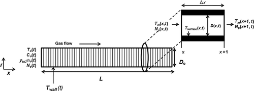
The model simulates particle deposition, removal and HC condensation for turbulent gas flow through a circular pipe at constant wall temperature. The computational domain of the model consists of a circular pipe of diameter (Do ) and length (L). The pipe was divided into several cells as shown in . The number of cells was chosen so that the model predictions were grid independent. also shows a single computational cell. Fluid flow and heat transfer were solved for each cell (x) at a given time step (t). It was assumed that at each time step steady-state was reached quickly. Hence, a steady-state solution was obtained at each time step and transient effects in the equations were neglected. The time-steps in the model were fixed at 1 s. Particle deposition and removal equations were solved for each computational cell and at each time step. HC condensation was solved for each cell and was coupled to the particle deposition. Particle deposition and HC condensation leads to a reduction in the tube diameter. The tube diameter calculated at a particular time step [D(x,t)] was used as input for the next time step (t + 1). The deposit surface temperature, i.e., the temperature at the interface of gas and deposit was determined from an energy balance.
The gas temperature at the tube inlet [To (x = 0, t)], soot mass concentration [Co (x = 0, t)] and mole fractions of the six HC species used in the model [y HC(i)o (x = 0, t)] were either constant or could vary as a function of time, i.e., the boundary conditions could vary at each time step. This allowed for input of experimental data directly into the model; for example, boundary conditions from an EGR cooler fouling schedule. Due to its high specific heat, engine coolant circulated through EGR coolers typically encounters less than 2°C increase in its temperature. Hence, the tube wall was assumed to be at a constant temperature [T wall(t)] at any given time step. Other inputs to the model were the average gas pressure in the tube [P avg(t)], the total number concentration of soot particles at the tube inlet [No (x = 0, t)] and the mass flow rate (mg ) through the tube.
Some of the assumptions made in the model were:
| • | Variations in the radial direction were neglected. | ||||
| • | Fully developed turbulent flow was assumed in the tube and entrance effects were neglected. | ||||
| • | Properties of air were used for bulk EGR gas properties since it made up more than 95% of the flowing gas mixture in experimental measurements. | ||||
| • | It was assumed that the properties of the deposit formed by soot deposition and HC condensation, namely thermal conductivity and density, were constant and did not change as a function of temperature, deposit thickness or time, i.e., the deposit properties did not change at each time step. | ||||
2.1. Governing Equations for Bulk Fluid Flow and Heat Transfer
Properties of air including density, viscosity, thermal conductivity, and specific heat were used for EGR gas and were calculated at each time step (t) using ideal gas assumption at an average temperature of the gas inlet and wall temperature as:
It was assumed that the properties did not vary as a function of the axial distance along the tube. The governing equation for the mean gas temperature [Tm (x,t)] as a function of axial distance (x) at time step (t) was obtained from energy conservation on a single computational cell (Housiadas and Drossinos Citation2005; Incropera et al. Citation2007; Abarham et al. Citation2009a).
Solving for Tm (x,t) and replacing T wall(t) by T surface(x,t), where T surface(x,t) is the temperature of the surface of the deposit layer at the interface between the gas and the deposit:
The wall shear stress (τ s ) and the friction velocity (u*) are defined as (Incropera et al. Citation2007):
Different expressions have been suggested for the thickness of the viscous sublayer in the turbulent boundary layer by Housiadas and Drossinos (Citation2005) and Byers and Calvert (Citation1969). In our model the thickness of the viscous sublayer (δ) is defined as (Yung et al. Citation1989b; White Citation2003; Abarham et al. Citation2009a):
2.2. Particle Deposition
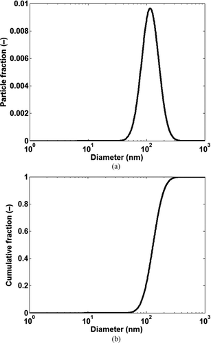
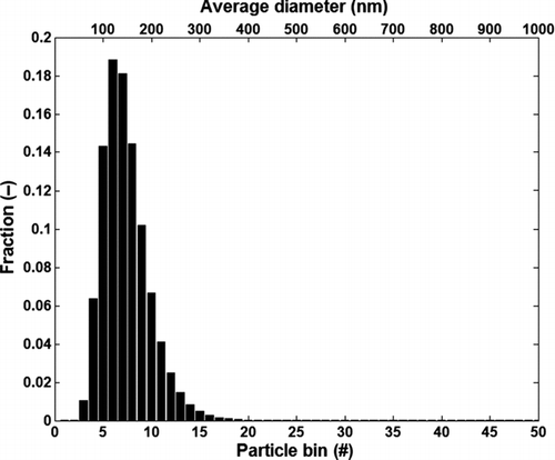
It was assumed that the soot particles at the inlet of the tube at any time step are lognormally distributed with a mean diameter of 130 nm and a standard deviation of 1.4 as shown in and b. Lognormal distribution is a commonly reported distribution for particles in diesel exhaust (Mehta et al. Citation2001; Harris and Maricq Citation2002). The values of mean diameter and standard deviation were chosen to match the particle distribution in the experimental test cases described in detail later in the paper. It was assumed that the particles were spherical with a constant density (ρp ) of 1.8 g/cc (Vishwanathan and Reitz Citation2008; Lance et al. Citation2009). The total number of particles between 1–1000 nm at the channel inlet was divided into 50 bins to reduce computational requirements. If sufficient computational power is available the particle deposition and removal equations could be solved for each particle diameter. Since the particles found in EGR coolers are typically < 200 nm, a higher resolution of particle bins could be used up to 200 nm, while a coarser resolution could be used from 200 to 1000 nm. As a starting point the width of each bin in the model was set to 20 nm and each bin was represented by an average diameter (dp avg). The fractional distribution of the particle bins as shown in was determined from the cumulative particle distribution at the channel inlet shown in and was calculated as:
Number concentration in each bin Np (dp avg) at the channel inlet was calculated from the fractional distribution of particle bins and the total number of particles [(N o(t)] at the inlet of the tube. It was assumed that the change in the number concentration within each particle bin along the tube occurred only due to particle deposition on the tube wall or removal of particles from the deposit layer, i.e., there was no coagulation of particles or interaction between the different particle bins. The number concentration in each particle bin for the next computational cell (x + 1) was calculated based on the current cell (x) at any given time step (t).
In every computational cell and at every time step particle deposition and removal equations were solved for each of the 50 particle bins using the average diameter (dp avg). It was assumed that all the particles in each bin behaved identically and their motion was governed by the average diameter (dp avg). The model takes into account soot particle deposition in turbulent pipe flow at constant wall temperature by the following mechanisms:
| • | Thermophoresis | ||||
| • | Diffusion | ||||
| • | Turbulent impaction | ||||
| • | Gravitational drift | ||||
Thermophoresis is particle motion due to thermal gradients. Collisions with more energetic gas molecules on the hot gas side versus the cold gas molecules near the tube wall leads to net motion of particles toward the wall. Two commonly used correlations in the literature for the drift velocity due to thermophoresis are the Brock–Talbot and modified MCMW correlations (Housiadas and Drossinos Citation2005; Hoard et al. Citation2008; Abarham et al. Citation2010a). In our model we have used the Brock–Talbot correlation given by:
where the Knudsen number (Kn) for each particle bin was calculated from the mean free path of gas molecules (λ).
It was assumed that the thermal conductivity of soot particles (kp ) was 0.5 W/mK and the thermophoretic constants A, B, C, Cs, Cm , and Ct were assumed to be 1.2, 0.4, 1.1, 1.14, 1.17, and 2.18 respectively (Lance et al. Citation2009; Abarham et al. Citation2010a).
The temperature gradient for a computational cell (x) at time step (t) was given by (Housiadas and Drossinos Citation2005):
Particle deposition could also occur inertially if the particle was unable to follow the flow depending on the particle relaxation time. Smaller diameter particles have short relaxation times and are able to follow the flow while larger particles are unable to do so. The drift velocity due to inertial impaction in turbulent flow (Vt ) for each particle bin in every computational cell (x) at time step (t) is defined as (Abarham et al. Citation2010a):
where the particle relaxation time (τ p ) was calculated from the Cunningham slip correction factor (Cc ).
Finally the gravitational drift velocity (Vg ) for each particle bin in every computational cell (x) at time step (t) is defined as (Abarham et al. Citation2010a):
It was found from the above analysis and has been reported by other researchers, Abarham et al. (Citation2010a) and Hoard et al. (Citation2008), that thermophoresis was the dominant deposition mechanism for the range of particles typically found in EGR coolers. The drift velocities due to other deposition mechanisms were retained in the model for completeness and to keep the model versatile enough to predict particle deposition in turbulent pipe flows encountered in other applications, where the range of particle diameters might be different.
2.3. Particle Removal
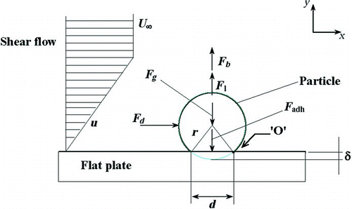
There are several forces acting on a spherical particle attached to the surface as shown in (Abd-Elhady et al. Citation2010). Removal of deposit mass was calculated in the model by considering a simple force balance between only the drag and van der Waals forces acting on each deposited particle bin. The lift force and particle weight were found to be not comparable to the drag and van der Waals forces. It was assumed that there was no interaction between the deposited particle bins in the fouling layer. The drag force (FD ) due to fluid flow acting on a particle bin in a cell (x) at time step (t) is given by (Yung et al. Citation1989b):
FIG. 4 Different forces acting on a particle resting on a flat surface and exposed to a shear flow. Point O is the fulcrum of rolling. (Abd-Elhady et al. Citation2010).
Where A H is the Hamaker's constant, which was assumed to be 10−20 J (Abarham et al. Citation2010a) and Ho is the separation between particles, which was assumed to be one-fiftieth of the particle diameter (dp avg).
Not all particles that migrate to the tube walls adhere to the surface. A sticking probability (S) was defined to determine the fraction of particles approaching the wall that actually adhere to the surface (Epstein Citation1997). The sticking probability for a particle bin in a cell (x) at time step (t) was calculated as: If
In reality, the particle agglomerates attached to the surface may not be spherical and can have a range of non-spherical geometries. The assumption of sphericity for the particles will, therefore, limit the accuracy of the forces acting on the particle as well as the sticking probability calculated in the present model. This can be improved further by accounting for the morphology of diesel particulate matter.
2.4. Particle Conservation
The mass deposited by a single particle bin in a computational cell (x) at time step (t) is given by:
So, the total mass deposited by all particle bins in the cell (x) at time step (t) is obtained by a summation over all the particle bins:
where (massdeposit) is the total accumulated mass in the deposit for a single particle bin (dp avg) in cell (x) up to the previous time step (t − 1). The accumulated mass of each particle bin in the deposit layer is known from particle mass conservation applied to each computational cell at every time step. The strength of scale factor (ψ) was assumed to be 1. The criterion for removal of accumulated mass for each particle bin in the deposit layer in cell (x) at time step (t) was defined as:
The total deposit mass removed from cell (x) at time step (t) for all particle bins is given by:
The net soot mass accumulated in cell (x) at time step (t) is given by:
This approach of solving particle deposition and removal equations for each particle bin enabled the model to predict the evolution of the particle distribution in the gas along the channel as well as the mass distribution in the deposit layer.
2.5. HC Condensation
The EGR cooler feed gas in a diesel engine consists of several HC species. Heavier HC species are more likely to condense at the coolant temperatures (30–90°C) typically encountered in diesel engine EGR coolers. The model took into account condensation of six HC species as listed in . Sluder et al. (Citation2008) found that the gas chromatograph/mass spectrometer (GC/MS) chromatograms for deposits in surrogate tubes fouled by exhaust from a diesel engine had a peak approximately around C19–C20, both of which are present in diesel fuel in significant quantities. They also found that the tube cooled by coolant at 40°C temperature retained HCs as light as C15. Species like C25 and beyond are present in diesel fuel at insignificant levels and are typical of the lowest end of the lubricating oil HC distribution (Sluder et al. Citation2008). The mass condensation flux (jg ,i ) from the gas stream to the surface is defined as (Hoard et al. Citation2008):
TABLE 1 HC species included in the model
where (yi ,gas) is the mole fraction of the HC species in the gas stream determined from experimental measurements and (yi ,int) is the mole fraction of the HC species at the gas/liquid interface. The mass transfer coefficient (Kg ) is defined as:
Since the heat transfer coefficient (h) is related to the Nusselt number (Nu) the mass condensation flux can be rewritten as:
where, the Schmidt number for each HC species (Scg
,i
) was calculated using the diffusivity of each HC species in air (![]() ). The mass diffusivity of each HC species in air (
). The mass diffusivity of each HC species in air (![]() ) at standard conditions was obtained from Yaws (Citation2010) and was corrected for temperature and pressure using the average gas temperature and pressure in the EGR cooler assuming ideal gas behavior as shown by Incropera et al. (Citation2007).
) at standard conditions was obtained from Yaws (Citation2010) and was corrected for temperature and pressure using the average gas temperature and pressure in the EGR cooler assuming ideal gas behavior as shown by Incropera et al. (Citation2007).
The mole fraction of the HC species at the gas/liquid interface (yi ,int) is given by:
The partial pressure of each HC species was calculated using the respective Antoine coefficients for each species similar to the approach of Abarham et al. (Citation2009b):
Antoine coefficients for each HC species were obtained from Yaws et al. (Citation2009). The mass condensed for a HC species in a single computational cell at time step (t) is:
The mole fraction for a particular HC species at the inlet of the next computational cell (x + 1) was calculated based on molar conservation applied to the current cell (x). It was assumed that all the condensed HCs diffuse through the deposit and migrate toward the cold wall as reported by Lance et al. (Citation2010) from their optical microscopy measurements on deposits from field fouled EGR coolers. The cold wall inhibits the evaporation of the condensed HCs. Hence, evaporation of condensed HC species from the deposit was not included in the model.
2.6. Calculation of Various Parameters
The total mass deposited in cell (x) at time step (t) is the summation of the net soot mass and the condensed HC mass:
The local thickness of the deposit layer (φ) is given by:
where (ρ deposit) is the density of the deposit layer. In our model, the density of the deposit layer was assumed to be 35 kg/m3 as reported by Lance et al. (Citation2009). It was assumed that the density of the deposit layer was constant throughout the tube and did not change with deposit thickness or temperature. The diameter of the tube in cell (x) at the next time step (t + 1) is calculated from the current time step (t):
There is convective heat transfer from the bulk gas to the deposit layer and there is conduction heat transfer across the deposit to the tube wall. The temperature at the surface of the deposit layer, i.e., at the interface between the deposit layer and the gas was calculated from a heat transfer balance by solving the equation:
where the local heat transfer coefficient [h(x,t)] is calculated from the local Nusselt number [Nu (x,t)]. The thermal conductivity of the deposit layer (k deposit) was assumed to be 0.05 W/mK (Lance et al. Citation2009). It was assumed that the thermal conductivity of the deposit layer was constant throughout the tube.
Some of the heat exchanger performance metrics were also calculated in the model. The effectiveness (ϵ) was defined as:
The thermal resistance (R th) was defined as:
where A o is the surface area for heat transfer, LMTD is the logarithmic mean temperature difference and Q is the heat transfer from the tube. The fouling layer thermal resistance (Rf ) is defined as:
3. MODEL EVALUATION
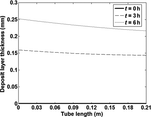
The model was used to calculate fouling of a single tube exposed to exhaust gases for 6 h. The boundary conditions for a test case used to evaluate the model are given in , while the concentrations of the six HC species are given in . The tube geometry and the inlet particle size distribution were chosen to match the experimental data described in the next section. The HC concentration values do not represent actual measurements, but were chosen to test the model. shows the deposit layer thickness along the tube at 3 different exposure times. Maximum deposit thickness occurs at the tube inlet due to the highest temperature gradient and thereby thermophoretic effect.
TABLE 2 Boundary conditions of test case for model evaluation
TABLE 3 HC species concentrations
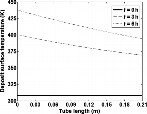
The deposit surface temperature, i.e., temperature at the interface of the deposit layer and bulk gas also decreases along the length of the tube, while it increases as a function of time as shown in . Due to the thicker deposit layer at the tube inlet, heat transfer through the deposit is inhibited due to its low thermal conductivity leading to the highest deposit surface temperature at the tube inlet. As the deposit layer grows with time, the deposit surface temperature increases from the initial wall or coolant temperature at t = 0 due to inhibition of heat transfer across the deposit.
FIG. 6 Variation of the surface temperature of the deposit layer along the tube length at different exposure times.
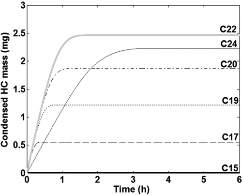
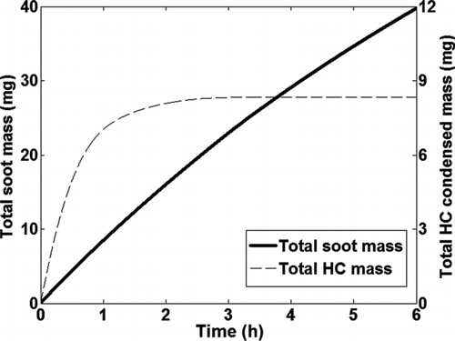
Condensation of HC species was coupled to the soot deposition model. The condensed mass for the six HC species (C15–C24) deposited in the tube as a function of time is shown in . As mentioned earlier, it is assumed that all the condensed HCs diffuse through the deposit and migrate toward the cold wall (Lance et al. Citation2010). The cold tube wall inhibits the evaporation of the condensed HCs. Hence evaporation of condensed HC species from the deposit is not included in the model. As the deposit surface temperature increases no further condensation occurs and therefore HC species, C17–C22, reach an asymptote between 0–1.5 h of exposure time, while C24 reaches an asymptote after about 3 h. It was observed that there is very little condensation of C15 at these boundary conditions. This indicates that lighter HC species in the exhaust will not condense under the operating conditions typically encountered in EGR coolers and thereby do not contribute to fouling. It was also observed that the HC condensation was more pronounced toward the tube exit due to the lower deposit surface temperatures, which is in contrast to particle deposition.
The net soot mass deposited in the tube is shown in as a function of time. The net soot mass deposited in the tube is about 13% of the total exposure over 6 h. Soot deposition due to thermophoresis continues to occur as long as a temperature gradient exists between the bulk gas and the deposit layer. The total condensed HC mass, which is the summation of the condensed mass for the six HC species considered in the model, is also shown.
FIG. 8 Net soot mass and total HC condensed mass deposited in the tube as a function of time over 6 h.
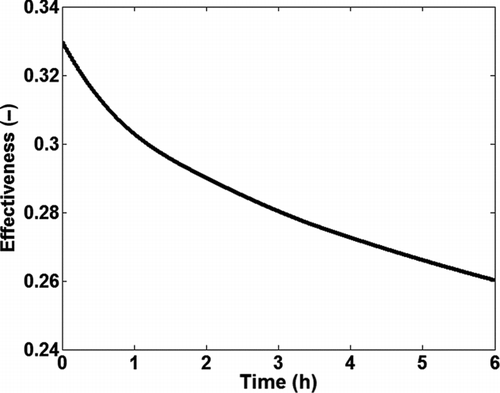
The total mass deposited in the tube is the summation of total deposited soot mass and condensed HC mass. The effectiveness of the single tube heat exchanger degrades over time due to reduction in heat transfer because of fouling as shown in .
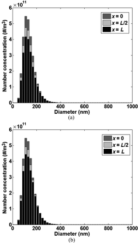
Using the particle bin approach, it was also possible to track the evolution of the particle distribution in the bulk gas through the channel, since it was assumed that change in the number concentration of each particle bin occurred only due to particle deposition or re-entrainment. and b show the distribution of the particle bins in the bulk gas at the tube inlet (x = 0), middle (x = L/2), and tube outlet (x = L) at t = ½ h and t = 6 h. Both figures can be used to visualize changes in the particle distribution in the bulk gas as it moves from channel inlet to outlet at a particular time step. Couple of observations can be made from the figures. First, at any given time step, as the feed gas moves along the channel there is a net decrease in the number concentration of different particle bins as particles are deposited on the channel wall and re-entrained into the gas flow due to shear removal. At both time steps (at t = ½ h and t = 6 h) the evolution of the particle distribution in the bulk flow is captured by the model as the feed gas moves from channel inlet to outlet. Second, at t = 6 h, thermophoretic particle transport, which is the dominant soot deposition mechanism, is reduced compared to t = ½ h due to the increase in the deposit surface temperature and consequent reduction in the temperature gradient between the bulk gas and the deposit. Also, due to the reduction in tube diameter, the bulk gas velocity increases leading to higher shear force on the deposit layer and therefore higher mass removal from the deposit layer.
FIG. 10 Evolution of the particle bin distribution in the gas along the tube. (a) t = ½ h; (b) t = 6 h.
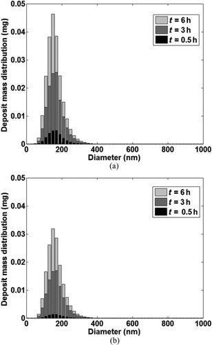
Similarly, the growth of the mass distribution in the deposit layer could also be calculated since it was assumed that there was no interaction between the deposited particle bins on the channel wall. The accumulated mass of each particle bin in the deposit layer is known at every time step from particle mass conservation applied to each computational cell. and b show the evolution of the mass distribution in the deposit layer as a function of time at the tube inlet and outlet. The total mass deposited at the tube outlet was lower compared to tube inlet due to the decreased temperature gradient.
FIG. 11 Evolution of the deposit mass distribution as a function of time at (a) Tube Inlet; (b) Tube Outlet.
This approach can thus be used to investigate the influence of different particle distributions on EGR cooler fouling as well as boundary conditions favorable for removal of particles of different diameters.
4. COMPARISON TO EXPERIMENTAL DATA
4.1. Experimental Setup
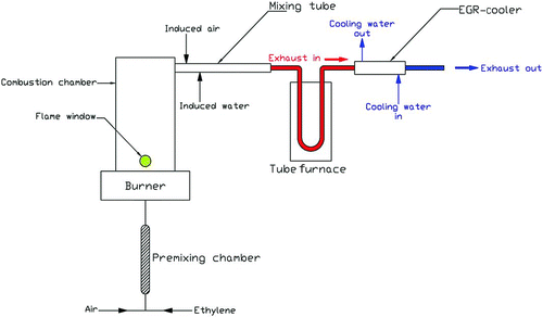
To validate the model, theoretical results were compared with the experimental data obtained from a laboratory reactor. The experimental laboratory reactor consisted of a soot generator, gas/particle flow heater, testing section for EGR coolers and an exhaust system as shown in . Details of the test setup and measurement procedures are fully described in Abd-Elhady et al. (2010). The soot particles are formed in the soot generator due to the incomplete combustion of ethylene (C2H4) and their size distribution is controlled by the stoichiometry of combustion. The mass flow rate of ethylene and air are measured and controlled using flow controllers for each gas. The average diameter of the soot particles was 130 nm with a standard deviation of 55 nm, which is similar to the particle size distributions reported in the literature for diesel engine exhaust by Wentzel et al. (Citation2003); Park et al. (Citation2004); Kittelson et al. (Citation2006); and Lapuerta et al. (Citation2007). The mass concentration of soot particles in the feed gas to the EGR cooler was 100 mg/m3. Soot particles produced by the soot generator were mixed with external air in the mixing tube as shown in . The mass flow rate of the injected air was controlled and measured using a mass flow controller. The mixture of air and soot particles was heated up to 400°C in a tubular furnace with 8 kW maximum power, to simulate the conditions of exhaust gasses from diesel engines. The hot mixture of gas and soot particles was then passed to the EGR cooler, which in the present investigation was a shell and tube type heat exchanger consisting of 1–3 corrugated circular tubes. It should be pointed out that the tubes used in the experimental setup were corrugated to improve the rate of heat transfer, while the circular tube used in the model was assumed to have a smooth surface. An independent water circuit was used to maintain the inlet temperature of the cooling water to the EGR cooler at a constant level of 80°C, to simulate the typical coolant temperatures in diesel engines (Zheng et al. Citation2004). The mass flow rate of the cooling water was controlled by a flow controller and was measured with an accuracy of ± 1%. The gas velocity through the EGR cooler was varied by changing the flow rate of the injected air, via a mass flow controller. The inlet gas velocity (V) through the EGR cooler was calculated from the measured mass flow rate (mg ) of the flowing gasses and the cross-sectional area (A cr) of the cooler tubes as follows:
FIG. 12 Schematic flow diagram of the experimental setup (Abd-Elhady et al. Citation2010).
4.2. Results and Discussion
Abd-Elhady et al. (2004, 2010) found that particulate fouling can be avoided if the gas velocity is above a critical flow velocity. The critical flow velocity is defined as the bulk velocity above which rolling of the deposited particles occurs. Abd-Elhady et al. (2010) used the laboratory reactor described above to experimentally investigate the influence of gas flow velocity on particulate fouling of EGR coolers, by operating the EGR cooler at gas velocities below and above the critical flow velocity. Their results were used to verify the model. In the experimental study three test cases were run, where everything was held constant except for the inlet gas velocity, which was varied by varying the amount of injected air. No HC species were introduced into the feed gas to the EGR cooler for these test cases. Hence, fouling of the cooler in these experiments is only due to soot. The boundary conditions for all three test cases are given in , which were used as inputs to the model.
TABLE 4 Boundary conditions for experiments
Since the tubes were exposed to the particle laden feed gas for about 6 h in the experimental measurements, the model was also used to calculate soot deposition in the tube for the same time duration. shows a comparison between the deposit thickness at the pipe inlet calculated by the model after 6 h of exposure and experimental measurements. The thickness of the deposit layer is highest at the tube inlet and decreases along the length of the tube. For the 120 m/s case the fouling layer thickness was very small and difficult to quantify in the experimental data.
show a comparison between the thermal resistance of the fouling layer calculated by the model and experimental data for the three inlet gas velocities. Overall there is good agreement between the model and experimental measurements. The model is able to predict the decrease in the fouling layer thermal resistance with increase in gas velocity as well as the differences in the initial rate of fouling between the three gas velocities.
FIG. 13 Comparison of effect of gas velocity on fouling layer thermal resistance between model and experiment for (a) 30 m/s; (b) 70 m/s; and (c) 120 m/s.
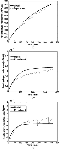
The shear force due to the gas flow is not sufficient to remove much of the deposited particles at 30 m/s inlet gas velocity, leading to a more or less continuous increase in the fouling layer, as shown in , in both experimental measurements and model predictions.
TABLE 5 Comparison of deposit layer thickness
Increasing the gas velocity further to 70 m/s, it can be observed that the fouling layer thermal resistance decreases with the flow velocity as shown in . The fouling process can be strongly reduced, but not completely prevented if the gas velocity is increased to 120 m/s. With increase in gas velocity the shear force on the deposit layer increases leading to increased removal of particle mass. An asymptotic value of fouling layer thermal resistance is reached for the 120 m/s case in both the model and experimental measurements as shown in , indicating an equilibrium between particle deposition and removal. The marginal discontinuities in the fouling layer thermal resistance versus time data from experimental measurements for gas velocity of 120 m/s are due to the successive breakage of the fouling layer and re-growth during the experimental run. It should be noted that a velocity of 120 m/s is not practical in current diesel EGR coolers.
There are some differences between the model and experiment especially for the 70 m/s gas velocity and in predicting the initial rate of fouling at 120 m/s. These differences could be due to corrugated tube geometry used in the experiment as opposed to a smooth tube used in the model. Among the assumptions and simplifications made in the model, the assumption of a constant deposit layer density and thermal conductivity along the length of the tube as well as the values used for these two properties could be an important source of the differences observed. Further work is required to understand the variation of these properties with temperature and layer thickness and implement them in the model.
5. SENSITIVITY ANALYIS
There are several assumptions and simplifications made in the model. The assumption of a constant deposit layer density and thermal conductivity along the length of the tube as well as the values used for these two properties are important parameters that affect the calculations made by the model. In reality, the deposit properties change with temperature and layer thickness. In the present model the values selected for these two properties were based on the findings of Lance et al. (Citation2009).
5.1. Thermal Conductivity of the Deposit Layer
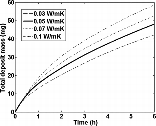
The test case described in was used to examine the sensitivity of the total deposit mass in the tube, as calculated by the model, to the thermal conductivity of the deposit layer. shows the total mass gain as a function of time calculated by the model for different values of deposit layer thermal conductivity, while the density was held constant at 35 kg/m3. shows the variation in the total mass gain calculated by the model, with the deposit layer conductivity of 0.05 W/mK used as the base case. The total deposit mass calculated by the model shows a 10–21% variation with a 40–100% change in the value of the deposit layer thermal conductivity used and a more or less linear relationship with the deposit thermal conductivity. As the deposit layer thermal conductivity is increased, the surface temperature of the deposit decreases, leading to a higher temperature gradient between the bulk gas and the deposit layer and, therefore, increased particle transport due to thermophoresis. The thermal conductivity of the deposit is mainly dependent on its porosity. Further experimental measurements with deposits of varying porosity are required to confirm the influence of deposit layer thermal conductivity on fouling.
TABLE 6 Effect of deposit layer thermal conductivity
5.2. Deposit Layer Density
The same test case was used to examine the sensitivity of the total mass gain in the tube, as calculated by the model, to the value used for the deposit layer density. shows the total mass gain calculated by the model with variation in the deposit layer density, while the thermal conductivity was held constant at 0.05 W/mK. shows the variation in the total mass gain calculated by the model, with the deposit layer density of 35 kg/m3 used as the base case. The total deposit mass calculated by the model shows a 12–16% variation with more than 40% change in the value of the deposit layer density used and a more or less linear relationship with the deposit density. As the deposit layer density is increased, the thickness of the deposit layer decreases leading to lower temperatures at the deposit surface due to increased heat transfer and, therefore, increased mass gain due to thermophoresis.
TABLE 7 Effect of deposit layer density
FIG. 15 Effect of deposit density on total deposit mass calculated by the model as a function of time.
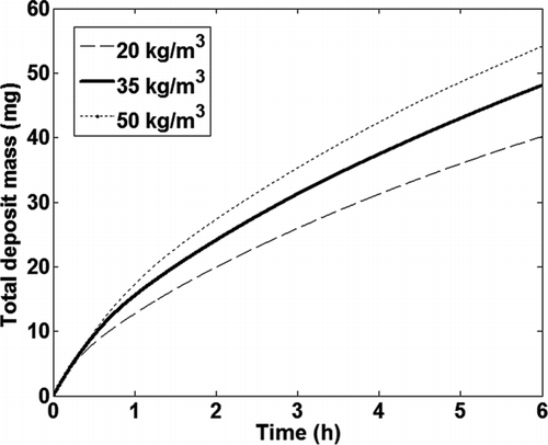
The total mass gain in the tube calculated by the model is influenced by the thermal conductivity and density of the deposit layer. To make the quantitative predictions of the model more robust, further work is required to implement the variation of deposit layer properties. Further experimental measurements of deposit properties from fouled EGR coolers will help in developing a model for the variation in fouling layer properties.
5.3. Particle Bin Distribution
The particle distribution at the tube inlet was divided into several bins to reduce the run time of the model. Ideally the particle deposition and removal equations could be solved for each particle diameter in the distribution. The base strategy used in the model was to divide the particles between 1–1000 nm into 50 bins of 20 nm width. A different particle bin distribution was used to examine its influence on the model calculations. Since the particles found in EGR cooler feed gas are typically < 200 nm, the particles between 1–400 nm were divided into 20 bins of 20 nm width, while particles between 400–1000 nm were divided into 6 bins of 100 nm width. Each particle bin was represented by a corresponding average diameter. The test case described in was used to examine the influence of this staggered particle bin distribution on model predictions. The difference in the total deposit mass over 6 h calculated by the model for the base and staggered particle bin distributions was less than 0.15%. This was true for other parameters calculated by the model as well.
6. CONCLUSIONS
A 1-D model was developed for soot particle deposition, soot removal, and HC condensation in turbulent pipe flow at constant wall temperature. The model took into account soot deposition due to thermophoresis, diffusion, turbulent impaction, and gravitational drift; although thermophoresis was found to be the most dominant deposition mechanism. Soot removal was modeled by considering a force balance between the drag force and van der Waals force. The model was capable of analyzing steady-state as well as transient boundary conditions from an EGR cooler fouling schedule. The model was able to predict growth of the fouling layer as well as several heat exchanger performance parameters under different boundary conditions. For the test case used to evaluate the model at boundary conditions similar to those observed in diesel engines, the model predicted a 21% drop in thermal effectiveness in just 6 h of exposure to soot laden gas flow. This degradation of cooler effectiveness is the main problem of EGR coolers. The total predicted mass gain was about 48 mg, which is about 13% of the total exposure over 6 h. The model could also predict the evolution of the inlet particle distribution in the bulk gas along the tube as well as the mass distribution in deposit layer on the tube walls, which can be used to investigate the influence of particle distribution in the bulk gas on fouling.
Predictions made by the model for deposit layer thickness and fouling layer thermal resistance were in reasonably good agreement with experimental data obtained from a laboratory reactor under the same boundary conditions. The final value of the fouling layer thermal resistance predicted by the model was within 10% of experimental measurements for the three inlet gas velocities. The model was also able to resolve differences in fouling behavior for three different inlet gas velocities.
The assumption of a constant deposit layer thermal conductivity and density as well as the values used for these properties influence the quantitative predictions of the model. The total deposit mass calculated by the model showed a 12–16% variation with a ±40% change in the value of the deposit layer density, while it varied by 10% with a 40% change in the value of the deposit layer thermal conductivity. Further investigations are required to include the variation of deposit layer properties with temperature and thickness in the model.
Acknowledgments
The authors wish to thank Mr. T. Zornek and Dr. Abd-Elhady of the University of Stuttgart for the experimental data and insights.
REFERENCES
- Abarham , M. , Hoard , J. , Assanis , D. , Styles , D. , Curtis , E. W. Ramesh , N. 2009a . Numerical Modeling and Experimental Investigations of EGR Cooler Fouling in a Diesel Engine . SAE Technical Paper Series: 2009-01-1506
- Abarham , M. , Hoard , J. , Assanis , D. , Styles , D. , Curtis , E. W. Ramesh , N. 2009b . Modeling of Thermophoretic Soot Deposition and Hydrocarbon Condensation in EGR Coolers . SAE Technical Paper Series: 2009-01-1939
- Abarham , M. , Hoard , J. , Assanis , D. , Styles , D. , Curtis , E. W. and Ramesh , N. 2010a . Review of Soot Deposition and Removal Mechanisms in EGR Coolers . SAE Technical Paper Series: 2010-01-1211
- Abarham , M. , Hoard , J. , Assanis , D. , Styles , D. , Sluder , C. S. and Storey , J. M. E. 2010b . An Analytical Study of Thermophoretic Particulate Deposition in Turbulent Pipe Flows . Aerosol Sci. Technol , 44 : 785 – 795 .
- Abd-Elhady , M. S. , Rindt , C. C. M. , Wijers , J. G. , van Steenhoven , A. A. , Bramer , E. A. and van der Meer , T. H. 2004 . Minimum Gas Velocity in Heat Exchangers to Avoid Particulate Fouling . Int. J. Heat Mass Tran. , 47 ( 17–18 ) : 3943 – 3955 .
- Abd-Elhady , M. S. , Zornek , T. , Malayeri , M. R. , Balestrino , S. , Szymkowicz , P. G. and Müller-Steinhagen , H. 2010 . Influence of Gas Velocity on Particulate Fouling of Exhaust Gas Recirculation Coolers . Int. J. Heat Mass Tran. , 54 ( 4 ) : 838 – 846 .
- Bohnet , M. 1987 . Fouling of Heat Transfer Surfaces . Chem. Eng. Technol. , 10 : 113 – 125 .
- Byers , R. L. and Calvert , S. 1969 . Particle Deposition from Turbulent Streams by Means of Thermal Force . I EC Fundam. , 8 : 646 – 655 .
- Epstein , N. 1997 . Elements of Particle Deposition onto Nonporous Solid Surfaces Parallel to Suspension Flows . Exp. Therm. Fluid Sci. , 14 ( 4 ) : 323 – 334 .
- Grillot , J. M. and Icart , G. 1997 . Fouling of a Cylindrical Probe and a Finned Tube Bundle in a Diesel Exhaust Environment . Exp. Therm. Fluid Sci. , 14 ( 4 ) : 442 – 454 .
- Harris , S. J. and Maricq , M. M. 2002 . The Role of Fragmentation in Defining the Signature Size Distribution of Diesel Soot . J. Aerosol Sci. , 33 : 935 – 942 .
- He , C. and Ahmadi , G. 1998 . Particle Deposition with Thermophoresis in Laminar and Turbulent Duct Flows . Aerosol Sci. Technol , 29 : 525 – 546 .
- Hoard , J. , Abarham , M. , Styles , D. , Giuliano , J. M. , Sluder , C. S. and Storey , J. M. E. 2008 . Diesel EGR Cooler Fouling . SAE Technical Paper Series: 2008-01-2475
- Housiadas , C. and Drossinos , Y. 2005 . Thermophoretic Deposition in Tube Flow . Aerosol Sci. Technol , 39 : 304 – 318 .
- Incropera , F. P. , Dewitt , D. P. , Bergman , T. L. and Lavine , A. S. 2007 . Fundamentals of Heat and Mass Transfer (6th ed. , 490 – 491 . New York : John Wiley & Sons . 498, 515, and 883
- Kern , D. Q., and Seaton , R. E. 1959 . A Theoretical Analysis on Thermal Surface Fouling . Brit. Chem. Engg. , 4 : 258 – 262 .
- Kittelson , D. B. , Watts , W. F. , Johnson , J. P. , Rowntree , C. , Payne , M. Goodier , S. 2006 . On-road Evaluation of Two Diesel Exhaust After-treatment Devices . J. Aerosol Sci. , 37 ( 9 ) : 1140 – 1151 .
- Lance , M. J. , Sluder , C. S. , Wang , H. and Storey , J. M. E. 2009 . Direct Measurement of EGR Cooler Deposit Thermal Properties for Improved Understanding of Cooler Fouling . SAE Technical Paper Series: 2009-01-1461
- Lance , M. J. , Sluder , C. S. , Lewis , S. and Storey , J. 2010 . Characterization of Field-Aged EGR Cooler Deposits . SAE Technical Paper Series: 2010-01-2091
- Lapuerta , M. , Martos , F. J. and Herreros , J. M. 2007 . Effect of Engine Operating Conditions on the Size of Primary Particles Composing Diesel Soot Agglomerates . J. Aerosol Sci. , 38 ( 4 ) : 455 – 466 .
- Loo , C. E. and Bridgwater , J. 1985 . Theory of Thermal Stresses and Deposit Removal . Powder Technol. , 42 : 55 – 65 .
- Mehta , D. , Alger , T. , Hall , M. J. , Matthews , R. D. and Ng , H. 2001 . Particulate Characterization of a DISI Research Engine using a Nephelometer and In-Cylinder Visualization . SAE Technical Paper Series: 2001-01-1976.
- Müller-Steinhagen , H. , Reif , F. , Epstein , N. and Watkinson , P. 1988 . Influence of Operating Conditions on Particulate Fouling . Can. J. Chem. Eng. , 66 : 42 – 50 .
- Park , K. , Kittelson , D. B. and McMurry , P. H. 2004 . Structural Properties of Diesel Exhaust Particles Measured by Transmission Electron Microscopy (TEM): Relationships to Particle Mass and Mobility . Aerosol Sci. Technol , 38 : 881 – 889 .
- Royer , M. , Davidson , J. H. , Francis , L. F. and Mantell , S. C. 2010 . Shear Induced Removal of Calcium Carbonate Scale from Polypropylene and Copper Tubes . J. Sol. Energy Eng. , 132 ( 1 ) : 0110131 – 0110139 .
- Sluder , C. S. , Storey , J. M. E. , Lewis , S. A. , Styles , D. , Giuliano , J. M. and Hoard , J. 2008 . Hydrocarbons and Particulate Matter in EGR Cooler Deposits: Effects of Gas Flow Rate, Coolant Temperature, and Oxidation Catalyst . SAE Technical Paper Series: 2008-01-2467
- Vishwanathan , G. and Reitz , R. D. 2008 . Numerical Predictions of Diesel Flame Lift-off Length and Soot Distributions under Low Temperature Combustion Conditions . SAE Technical Paper Series: 2008-01-1331
- Wentzel , M. , Gorzawski , H. , Naumann , K.-H. , Saathoff , H. and Weinbruch , S. 2003 . Transmission Electron Microscopical and Aerosol Dynamical Characterization of Soot Aerosols . J. Aerosol Sci. , 34 ( 10 ) : 1347 – 1370 .
- White , F. M. 2003 . Fluid Mechanics (5th ed.) , McGraw-Hill International .
- Witze , P. O. Diagnostics for the Measurement of Particulate Matter Emissions from Reciprocating Engines . Proceedings of the Fifth International Symposium on Diagnostics and Modeling of Combustion in Internal Combustion Engines – COMODIA: 7–12.
- Yaws , C. L. , Narasimhan , P. K. and Gabbula , C. 2009 . Yaws’ Handbook of Antoine Coefficients for Vapor Pressure , 2nd Electronic Ed. Knovel, New York
- Yaws , C. L. 2010 . Yaws’ Transport Properties of Chemicals and Hydrocarbons (Electronic Ed.) Knovel, New York
- Yung , B. P. K. , Merry , H. and Bott , T. R. 1989a . The Role of Turbulent Bursts in Particle Re-entrainment in Aqueous Systems . Chem. Eng. Sci. , 44 ( 4 ) : 873 – 882 .
- Yung , B. P. K. , Merry , H. and Bott , T. R. 1989b . Effects of Particle-Surface Interactions on Deposition and Re-entrainment of a Particulate Fouling System . Geothermics , 18 : 327 – 335 .
- Zheng , M. , Reader , G. T. and Hawley , J. G. 2004 . Diesel Engine Exhaust Gas Recirculation—A Review on Advanced and Novel Concepts . Energ. Convers. Manage. , 45 ( 6 ) : 883 – 900 .
