Abstract
A turbulent burst model is used and evaluated for particle resuspension in ventilation ducts in this study. The model is a prolongation of the turbulent burst model developed by Cleaver and Yates with an approach to the critical jump-start air velocity for particle resuspension. This critical jump-start air velocity is introduced to estimate the fraction of particles resuspended under the turbulent burst. The model results were compared with experimental data that is available in literature. Both the model results and experiments show that resuspension rate increased with the increase of particle diameter and air speed in ducts. However, the model results did not show a significant decay of particle resuspension rate over time, which was shown in the experiments. Limitations of the model are discussed to explain the discrepancy between the model and the experimental results.
Copyright 2012 American Association for Aerosol Research
NOMENCLATURE
| A | = |
Hamaker constant |
| B | = |
The fraction of cleaned area of a flat under a turbulent flow per unit time |
| C | = |
Constant equal to(1−ν2 1)/E 1+(1−ν2 2)/E 2 |
| C′ | = |
Constant that determines decay speed of resuspension with time |
| D | = |
Duct diameter |
| Dag | = |
Diameter of aggregate |
| Dp | = |
Particle diameter |
|
| = |
Mean diameter of a burst |
| E | = |
Young's modulus |
| F | = |
Dimensionless force |
| F | = |
Fanning friction factor |
| K | = |
Rate constant |
| k 0 | = |
=Dag /Dp |
| Ma | = |
Adhesion moment |
| Mc | = |
Collision moment caused by aerosol particles |
| Md | = |
Aerodynamic drag moment |
| N | = |
The number of particles per area of surface at time t, also known as N(t) |
| N 0 | = |
The initial number of particles per area of surface, i.e., N 0 = N(t = 0) |
| Re | = |
Reynolds number |
| S | = |
Resuspension flux |
|
| = |
Lateral spacing between bursts |
|
| = |
Axial spacing between bursts |
| t | = |
Temperature |
| TB | = |
Mean period of a burst |
| T + B | = |
Dimensionless period of a burst |
| t | = |
Time |
| u | = |
Velocity |
| u* | = |
Friction velocity defined as |
| u ∞ | = |
Mean air speed |
| uc | = |
Critical jump-start air velocity |
| u* c | = |
Critical jump-start friction velocity |
| y | = |
Vertical distance from wall |
| y + | = |
Dimensionless vertical distance from wall defined as yu*/ν f |
| ze | = |
Separation gap between contact bodies |
| z 0 | = |
Mean micro-scale roughness height of the rough wall |
| α | = |
Fraction of surface under a burst that is cleaned from particles |
| φ | = |
Particle packing fraction |
| λ | = |
Fraction of area under a burst |
| μ f | = |
Dynamic viscosity of air |
| θ | = |
Contact angle of an aggregate with a wall |
| ν | = |
Poisson ratio |
| ν f | = |
Kinetic viscosity of air, defined as μ f /ρ f |
| ρ f | = |
Air density |
| ρ p | = |
Particle density |
| τ w | = |
Shear stress at wall |
1. INTRODUCTION
A large amount of dust particles deposit onto inner surfaces of ducts in ventilation systems, especially in places with high outdoor particle concentration or in old buildings. The amount of accumulated dust in ducts could reach as high as 5 g/m2 in newly constructed buildings (Holopainen et al. Citation2002) and those occupied for less than 1 year (Pasanen et al. Citation1997), while many existing standards require a threshold limit value of 1 g/m2. For old buildings, the amount of dust in ventilation ducts was found to exceed the local hygiene standards for many cities in China (Zhao and Chen Citation2006).
The accumulated dust particles in the ventilation ducts may be resuspended as air passes by. This will inevitably affect downstream indoor particle concentration and, consequently, increase occupation exposure to airborne particles. Moreover, microorganisms that grow in the dust are carried along with resuspended particles (Bluyssen et al. Citation2003) and this makes indoor air harmful to human health. Therefore, providing a reliable computational model to predict the amount of resuspended particles from the inner surface of ducts of ventilation system will play an important role on maintenance of ventilation system as well as indoor air quality.
Particle resuspension is a phenomenon in which particles are detached from a surface under the disturbance of a fluid flow. It is becoming increasingly important today in industries, such as air cleaning, health care, and semiconductor manufacturing. Due to its broad engineering application, mechanisms of particle resuspension in turbulent flow have attracted attention of many researchers. Currently, there are two general models for particle resuspension (Ziskind et al. Citation1995): the force/moments balance model and the energy balance model. The force balance model assumes that a particle is detached from a surface when hydrodynamic lifting force exceeds the adhesive force, while the moment balance model assumes the detachment occurs when external force moment overcomes the resisting moment caused by adhesive force (Soltani and Ahmadi Citation1994). The energy balance model assumes that kinetic energy of a particle in oscillatory motion can be increased by the energy transferred from turbulent fluctuations, and the particle is released once kinetic energy overcomes the adhesion potential well (Reeks et al. Citation1988; Reeks and Hall Citation2001).
The force/moments balance model focuses on different forces exerted on a single particle. Wang (Citation1990) illustrated the mechanisms of particle detachment considering a spherical particle in contact with a flat surface, where adhesive force and removal force are exerted on the particle. Wen and Kasper (Citation1989) calculated particle resuspension rate in a way that is similar to kinetic desorption of molecules from a surface and used dimensionless force in the form of adhesive force over removal force to demonstrate effects of the two forces on a particle. Mortazavi (Citation2005) theoretically calculated adhesive forces and removal force exerted on a particle deposited in a glass capillary tube at certain conditions. His calculation suggests that no particles should be resuspended in his experiment, which contradicted with the experimental results. He mentioned that strong bursts into viscous sublayer or existence of unstable particles may have been the reason for resuspended particles with a dimensionless force much greater than 1. He thus modified the Wen–Kasper model by multiplying resuspension rate by a fraction of loose particles to match the experimental results. While that Van der Waals force greatly exceeding lift force makes resuspension difficult in Wen–Kasper model; and energy model have difficulty calculating distribution and variation of dimensionless adhesive radius, researchers have been focusing on turbulent burst model. Phares et al. (Citation2000) designed an experiment in a purely laminar flow to show the significance of turbulent burst in viscous sublayer. Shortly after, Reeks et al. (2001) improved the energy model considering for drag torque, lift torque as well as inertia moment of the particle in turbulent burst.
In this study, a turbulent burst model is used and tested for modeling of particle resuspension rate in ventilation ducts. It focuses on the fraction of particles resuspended under the turbulent burst by introducing a new approach to the critical jump-start air velocity for particle resuspension. Then, the model is tested and evaluated by comparing with experimental results obtained by Nicholson (Citation1993), Giess et al. (Citation1997), and Lengweiler (Citation2000).
2. THEORETICAL MODEL
2.1. Model Based on Turbulent Bursts
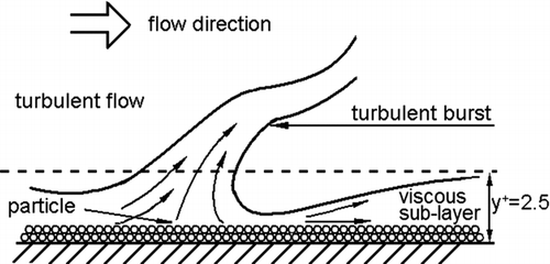
Investigations of turbulent boundary layer have shown that the turbulent boundary layer is unsteady and is continually disrupted by turbulent “burst.” Cleaver and Yates (Citation1973) believe that random bursts occur in the viscous sublayer as close as y+ = 2.5 from a surface as shown in , where y+ is the vertical dimensionless distance from the wall defined as: y+ = yu*/νf . The unsteady turbulent burst can cause particles to move and detach from the surface into the main flow. Particles can be ejected to the main flow when it passes the viscous sublayer.
FIG. 1 Schematic diagram of a turbulent burst near the wall (Cleaver and Yates Citation1973).
Based on observation, Cleaver and Yates (Citation1973) assumed that turbulent burst took place with a random frequency on the surface shown as . Each turbulent burst area can be treated as a circular area. Define the distance in the direction of main flow between two bursts as axial distance and the distance vertical to main flow direction between two bursts as lateral distance. Cleaver and Yates (Citation1973) chose estimations for mean size and mean frequency of burst as follows:
Schematic diagram of turbulent burst distribution on the surface (Cleaver and Yates Citation1973).
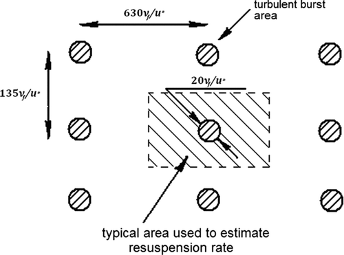
Mean duration of a burst is:
Mean diameter of a burst is:
Lateral spacing is:
Suppose the fraction of turbulent burst area on the entire surface is λ. Then,
In the equations above, u* is the friction velocity and it is defined as ![]() , where τ
w
is the shear stress at the wall and ρ
f
is the density of the air. For air flow in a ventilation duct, u* could be calculated by
, where τ
w
is the shear stress at the wall and ρ
f
is the density of the air. For air flow in a ventilation duct, u* could be calculated by
If the fraction of particles resuspended under one turbulent burst is α, then the fraction of resuspended particles on a flat under a turbulent flow per unit time, B, can be calculated as
The estimations for the mean size and mean frequencies of bursts was based on the visual observations of the turbulent bursts on a surface by Kline et al. (Citation1967), Corino and Brodkey (Citation1969), Kim et al. (Citation1971), Wallace et al. (Citation1972), Morrison et al. (Citation1971), and Rao et al. (Citation1972).
The above mentioned work of describing turbulent burst contributing to resuspension mechanism is remarkable; however, precise calculation of the fraction α of resuspended particles under one burst is not given in the previous work. Cleaver and Yates did not provide a method to calculate α. They only pointed out that the value of α could be estimated based on the assumption that it is proportional to wall shear stress (Cleaver and Yates Citation1973). To further develop this model, we introduce the critical jump-start friction velocity under which the particles begin to resuspend by the effect of the turbulent burst to estimate α. Then α can be estimated as.
Denote the number of particles per area of surface (particles number load of the surface) as N(t), and the rate constant, K, is defined as (Wen and Kasper Citation1989)
Particle resuspension flux, S, (the number of particles detached from a unit area in a unit time) is calculated by
Then, we can get
Particle resuspension rate, R, is defined by (Mortazavi Citation2005)
Integration of EquationEquation (15) gives
So, we have
Substituting expression of K into R gives
In EquationEquation (19), u* is the friction velocity that can be calculated using Equations Equation(6) and Equation(7). u* c , the critical jump-start friction velocity under which particles start resuspending under the effect of turbulent burst, is the key parameter for the calculation of R.
2.2. Critical Jump-Start Air Velocity
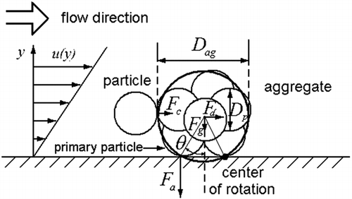
To calculate the critical jump-start air velocity, we employed the particle aggregate model as shown in . This model takes into consideration the fact that particles on a surface can easily form aggregates. The critical condition for the resuspension of a particle or an aggregate can be explained by a moment balance model:
EquationEquation (20) incorporates the moments of forces caused by adhesion, aerodynamic drag, and collision of deposited particles (aggregates) with an aerosol particle. Comparing with the study by Soltani and Ahamdi (1994), we neglect the moment of lift force because both Theerachaisupakjj et al. (2003) and Soltani and Ahmadi (Citation1994) pointed out that the moment of lift force was negligible. We do not incorporate the moment of the surface stresses shown by Soltani and Ahmadi (Citation1994). As this moment is intended for individual spherical particles, whereas our subject is aggregate, it is challenging to get the exact expressions for the moment of the surface stresses. In addition, our model follows the study by Theerachaisupakjj et al. (2003), where they showed that the modeled results were reasonably consistent with their measured data. Thus, we think the model should work for this study.
Md is approximated as (Theerachaisupakij et al. Citation2003)
Theerachaisupakij et al. (Citation2003) provided the expression for Mc
Ma is calculated based on the suggestion that the main adhesion force is Van der Waals force acting between the primary particle and the wall.
Substituting Equations (Equation21), (22), and (24) into EquationEquation (20) gives
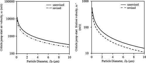
The critical jump-start air velocity can be calculated by solving EquationEquation (25). shows the sample calculation of the critical jump-start air velocity based on the conditions/parameters listed in .
TABLE 1 Condition/parameters for critical jump-start air velocity calculation shown in Figure 4
shows that in typical ventilation ducts, the critical jump-start air velocity (solid lines) is 300 m/s or higher. It is so large that particles with diameter ranging from 0.1 to 10 μm can hardly detach from the duct surface with a typical air speed of 3–10 m/s. However, previous observations indicated that particles were easily resuspended in ventilation ducts with average air speed as low as 1 m/s (Lengweiler Citation2000). This is because the critical jump-start air velocity in was calculated from force/moment balance model with the assumption that the viscous sublayer was steady. Previous research has shown that for very small particles especially those sitting on the substrate and deeply buried in the sublayers, the lift force on a particle is negligibly small comparing to adhesive force when there is no turbulent burst.
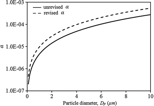
If the air speed in a typical ventilation duct is 5 m/s and the parameters are derived from , then α can be calculated by EquationEquation (9). The result is shown in (solid line).
In EquationEquation (24), adhesion force exerted on an aggregate is the Van der Waals force between a sphere and a flat, which works for monolayer of deposited particles. For the real cases occuring in ventilation ducts, however, there are multilayer deposited particles. The particles in the top layer are much easier to resuspend as they are governed by the Van der Waals force between particles, which is less than the Van der Waals force between a single particle and a flat surface (Hamaker Citation1937). Therefore, we modify the Van der Waals force using EquationEquation (28) to calculate the adhesive moment in EquationEquation (24).
Now, we get the revised adhesion moment Ma as
The revised critical jump-start velocity is replotted in (dashed lines). It shows a slight decrease of critical jump-start velocity compared with the unrevised one in . Substituting revised critical jump-velocity into expression of α, we get the revised α in (dashed line). It could be seen that α is not significantly increased (still about two orders of magnitude smaller than the estimated value of Cleaver and Yates) although Van der Waals force is determined based on a different approach. Cleaver and Yates mentioned “Some idea of the possible values of α can be obtained by considering the actual sizes of control element for typical values of τ w (wall shear force) as reported by References.” Three values of τ w were reported in these References (references listed in their paper) as 500, 1000, and 5000 dyn/cm2, and Cleaver and Yates estimated α based on these three values of wall shear force. They assumed α to be in the order of 0.01 to enable a decay of the strength of the burst from its center. Take τ w = 1000 dyn/cm2 as an example, the corresponding u* is about 9 m/s. The focus of our model, however, is ventilation systems, where u* is less than 1 m/s. If we increase air speed to allow u* to reach 9 m/s, then the calculated α would be in the order of 0.01 to 0.1 for particles with sizes of 0.1–10 μm in diameters. Then, the calculated α is about 0.03 in our model. This is reasonably consistent with Clearer and Yate's estimation for particles with diameter of around 2 μm.
3. Calculated Particle Resuspension Rate
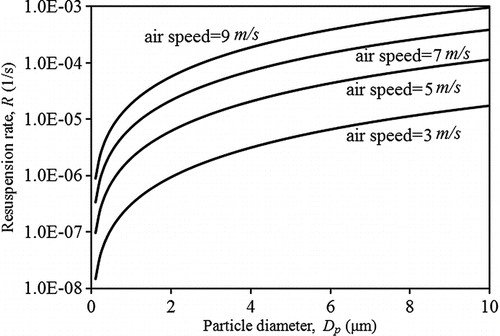
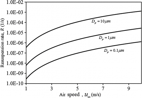
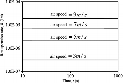
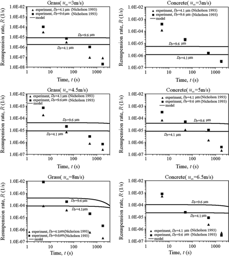
– shows the calculated particle resuspension rate with the parameters listed in . shows that larger particles tend to have higher resuspension rate; indicates that the particle resuspension rate increases with the average air speed in ducts. These results agree with those observed phenomena as summarized by Loosmore (Citation2003). shows that particle resuspension rate attenuates with time very slightly, almost remaining on the same level, which is not as that observed by Loosmore Citation2003.
4. TESTING OF THE MODEL
Experimental data in literature (Nicholson Citation1993; Giess et al. Citation1997; Lengweiler Citation2000) are compared with our model results. Nicholson and Giess's data are chosen because their experimental conditions were the closest to the conditions inside the ventilation ducts, although the experiments were carried out in wind tunnels and the surfaces were soil or concrete. Lengweiler's experiments were performed in a platform mimicking real ventilation ducts.
4.1. Comparison with the Experimental Data of Nicholson
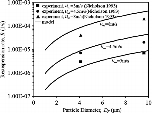
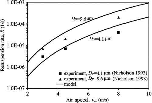
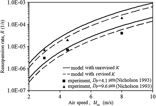
Nicholson (Citation1993) carried out his experiments on particle resuspension rate using a wind tunnel. The tunnel had a 1 m × 1 m cross section and the floor of the tunnel was made of concrete paving slabs or grass. The feed particles were spherical and made of silica with a standard density of 1000 kg/m−3. The diameters of their monodisperse particles were as 4.1 ± 0.8, 9.6 ± 1.9, 17.5 ± 2.7, and 22.1 ± 3.2 μm. Resuspension rates were determined at wind speeds of 3, 5, and 6.5 m/s for concrete surface and 3, 4.5, and 8 m/s for grass surface. Measurements were conducted with durations of 10, 100, 1000, and 3600 s and mid-point of the durations was taken to relate to resuspension rate.
In order to compare with the experimental data, the parameters/conditions for the model are listed in . Resuspension rate of particles with diameters of 17.5 ± 2.7 and 22.1 ± 3.2 μm exceeding particle diameter range (0.1–10 μm) in ventilation ducts are not considered herein.
TABLE 2 Parameters of Nicholson's experiment
and show that the model is in agreement with Nicholson's experimental results at time = 50 s. However, shows that the experimental results revealed a significant decay in terms of time, while the resuspension rate from model remains almost the same.
4.2. Comparison with the Experimental Data of Giess et al.
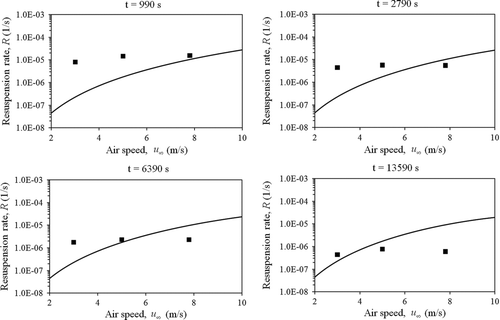
Giess et al. (Citation1997) measured the particle resuspension rate from grass under 3 different wind speeds (3, 5, and 7.8 m/s) in a wind tunnel with a cross section of 1.2 m × 0.8 m. The spherical particles were made of silica and their sizes are 1.85 (±0.5), 8.40 (±1.81), and 20.18 (±4.43) μm in diameter. Only resuspension rate of particles with diameter of 1.85 (±0.5) μm was determined experimentally and, therefore, is compared with our model results herein. The corresponding parameters are listed in .
Again, shows that theoretical model is in agreement with experimental results of Giess et al. On the other hand, the experimental results also showed a significant decay over time, which is not shown in the model calculated.
4.3. Comparison with the Lengweiler's Experimental Data
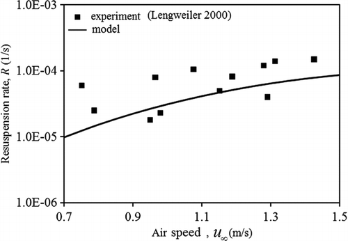
Lengweiler (Citation2000) measured particle resuspension rate of talcum powder in a ventilation duct. The particles are in the range of 0.1 to 30 μm in diameter with an average diameter of 4.5 μm. The working section of the duct was 1.2 m long and the cross section of the duct was quadrate with a side length of 0.5 m. This configuration is similar to that of a typical ventilation system. In his experiments, only the air speed was changed from 0.1 to 1.5 m/s with all other parameters remained constant. The tested surface in his experiment was wood-fiber plates that were painted black, and the relative roughness was greater than a typical steel surface.
In order to match the experimental conditions, the parameters in our model were estimated and listed in . The results of the resuspension rate plotted in show that the model agree well with experiment.
TABLE 3 Parameters of Giess et al.'s experiment
5. DISCUSSIONS
The presented model is an extension of Cleaver and Yates's turbulent burst model with an assumption that lift force exceeding adhesive forces occurs in accordance with the time and space distribution of turbulent burst. The turbulent burst is a statistical characteristic of turbulent flow through ducts. Since turbulent bursts appear periodically and randomly over time and space and resuspension is a result of turbulent burst, the model also tends to be discrete over time and space. The time interval between each two adjacent turbulent bursts is not a fixed amount, and thus resuspension within the time interval is not a fixed amount. Thus, this model is rather than quantum-like but discrete. The resuspension itself has a statistical component in which only the average period is estimated because our focus is more on resuspension on a macroscopic scale. The same theory applies to space interval of turbulent burst in the model.
TABLE 4 Parameters for model calculation of Lengweiler's experimental case
This improved turbulent burst model was based on the mechanism that strong turbulent burst in viscous sublayer can transfer aerodynamic energy to particles, resulting in detachment of some particles from the surface of the ventilation duct. However, this energy accumulation process involves energy loss: when estimating the critical jump-start velocity, the model took into consideration of both the aerodynamic drag force acting on aggregate and the collision force between the rolling particle and the aggregate particles. There is a loss of kinetic energy when the particle collides with the aggregate. For another case, when a rolling particle does not receive sufficient energy from the turbulent burst, it either remains in the viscous sublayer or does not collide with another particle or aggregate. As a result, the kinetic energy is totally lost for this case.
The presented model combines part features of the moment balance model (calculating critical jump-start velocity) and energy model (particle resuspension owing to turbulent burst). This is different from the energy model (Reeks et al. Citation1988; Reeks and Hall Citation2001), in which the particle is detached from the surface when it has accumulated enough vibrational energy to escape from the potential well.
5.1. Rate Constant K
Although the calculated particle resuspension rates are in agreement with the experimental data at a certain point, there is obvious discrepancy between the model results and experimental data in literature. This discrepancy is more obvious for the trend of particle resuspension rate against time. This is likely due to the use of rate constant K. Rate constant K in our model was assumed to be irrelevant to time (t). However, this assumption has not been well proved despite that Wen and Kasper (Citation1989) and Mortazavi (Citation2005) employed similar concept for gas desorption rate constant. They described the value of K as
Where F is the dimensionless force and K is the value corresponding to F = 0. With this assumption of rate constant we reached the resuspension rate in EquationEquation (18). With small rate constant K and time t, the particle resuspension rate would have the same order as K because e−Kt approaches to unity. Thus, we get EquationEquation (33), which is independent on time.
On the other hand, many researches have shown that the particle resuspension rate should decay over time. The correlation which has been described as an inverse correlation both theoretically (Reeks et al. 2001) and experimentally (Loosmore Citation2003):
FIG. 13 Comparison with the experiment of Lengweiler: resuspension rate versus u ∞, comparison of model and experiment.
Therefore, the rate constant K in the model is probably only a simplification that may affect the correlation between resuspension rate and time. A more reasonable assumption may be that K is a function of time. In order to match better with the aforementioned experimental data, K can be assumed to be in the following form.
Where K(t=0) stands for the initial relative change rate of particle numbers on the surface (EquationEquation 12). C′ is a constant which determines the decay speed of resuspension. Here, we use C′t+1 instead of t in the denominator in EquationEquation (39). It allows the function to be solved by integration and this is consistent with the initial condition for K.
Substituting EquationEquation (39) into EquationEquation (15) and by integration one can get
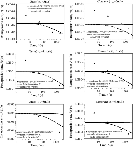
In this case, the resuspension rate in ventilation duct under parameters from is more relevant to time. shows that the resuspension rate calculated with the revised K agree with Nicholson's experimental data better. Despite of the difference between the revised model and the experiment, both showed the decline of resuspension rate over time. Therefore, it seems to be reasonable to assume that K is relevant. However, those factors deciding the value of K deserved to be further studied.
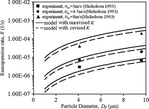
We further checked if the calculated resuspension rates with revised K agree with the experimental data for the cases shown in and . and show the results, which indicate the difference between revised and unrevised resuspension rate is insignificant in terms of particle diameter and air speed. However we believe that the model with revised K improved the model's accuracy because the revised model significantly improved the trend of the modeled particle resuspension rate versus time t.
TABLE 5 Model sensitivity analysis results
shows the correlation between Resuspension rate R and K, while shows the correlation between Resuspension rate R and particle number load N(Dp ) at a fixed time of t = 100 s, when K is constant. shows that the resuspension rate decreases with the decrease of the rate constant K. shows that at a certain time when K is a fixed number, the resuspension rate increases with the decrease of the particle load. The drop of particle number load N(Dp ) is reasonable due to the difference in the resuspension rates of different particle sizes.
shows that R is more sensitive to particle number load when Dp is small (or when N(Dp ) is large), while shows that R is more sensitive to K when K is smaller (implies time t is larger). It can be seen that when particle is smaller, resuspension rate depends more on particle load than on constant rate. With the progress of particle resuspension, the particle number load drops over time and the resuspension rate is more dependent on the rate constant.
5.2. Sensitivity Analysis
Sensitive analysis of the model was conducted using the variables listed in . The output of the model results are also shown in . The results are calculated by the model with the revised K as mentioned in Section 5.1 above.
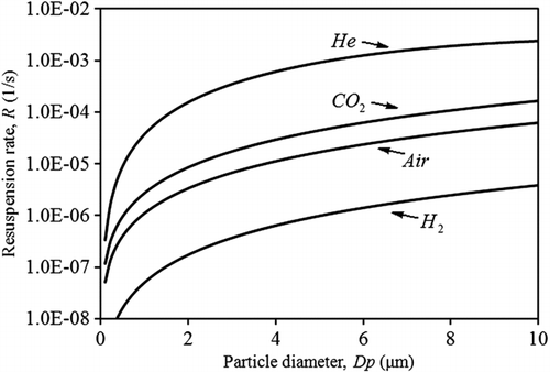
shows that resuspension rate R is the most sensitive to the air speed followed particle diameter Dp and then by separation gap ze . The resuspension rate decreases 3 orders of magnitude when time increases from 0 to 24 h. The range of t is based on the assumption that a typical ventilation system is turned on and off on a daily cycle. But in reality, a ventilation system may operate continuously. In this case, resuspension may not take place shortly after the system starts. Another factor is the viscous coefficient of the fluid ν f . In the sensitive analysis above, the fluid is not restricted to air. The properties (ν f and ρ f ) of gas at 20°C in the range of the lightest gas Hydrogen (H2) and a relatively heavier gas carbon dioxide (CO2) are considered. Both ν f and ρ f of fluid are important factors affecting the resuspension rate. shows the resuspension rate versus particle size with different working fluids with other parameters being the same as those listed in . It can be seen that fluid viscosity has an obvious effect on the resuspension rate.
FIG. 17 Resuspension rate R versus the revised rate constant K (air speed u ∞ is 5 m/s, particle diameter Dp is 5 μm, and time is from 0 to 3600 s).
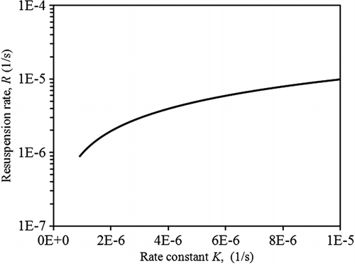
FIG. 18 Resuspension rate R versus particle load N(Dp ) at time t = 100 s (Since t is fixed, K remains constant), when air speed u ∞ is 5 m/s, particle diameter Dp ranges from 0.1 to 10 μm, the initial particle number load N 0 is set to be 8×10¹⁰ per m2.
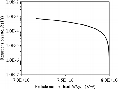
TABLE 6 Resuspension rate change with unit change of input parameters at typical value
FIG. 19 Particle resuspension rate with different working fluids (Helium, Carbon Dioxide, Air, and Hydrogen).
Although describes clearly how much will resuspension rate change when an input parameter changes in its possible range, it is not shown how fast resuspension rate will change. This draws the question of how resuspension rate will trend with unit changes in the fundamental parameters. further lists the change of R when the input parameters have a unit change based on their typical values (partial differential of R).
indicates that a unit change in Hamaker constant A and separation gap ze will change resuspension rate dramatically. Namely, resuspension rate changes fast at a fixed typical value of A and ze . It is easy to understand this finding because the absolute values of Hamaker constant and separation gap are so small, that even a tiny change of absolute magnitude in these 2 parameters may represent a large relative change. To analyze it mechanically, Mortazavi (Citation2005) has shown that Van de Waals force is the largest adhesion force among many of the adhesion forces acting on particles, including electrostatic force, capillary condensation force, etc. Hamaker constant and separation gap are both important parameters in EquationEquation (28). It can be seen that adhesion force in the model plays a significant role in determining resuspension rate.
Referring to the turbulent burst frequency and surface interaction size parameters of the bursts used to estimate resuspension rates, we follow the values by Cleaver and Yates (1973) as they concluded these values are typical for the cases of pipe-flow and flow over a flat-plate, which included the cases of fully developed turbulent flow in ventilation ducts. Thus, they are not included in the sensitivity analysis.
5.3. Limitation of Current Work
Theoretically, we can calculate particle resuspension rate once we obtain the necessary input parameters for the model. However, we acknowledge that it is difficult to obtain or confirm some of the parameters. For instance, the complex geometries of particle agglomerates and rough, stochastically sized particles, as well as their relationships with the walls may play important roles on particle resuspension. Furthermore, there might exist the cases that the particles with significant permanent dipole moments in their surface composition and their interaction with either metallic or plastic surfaces or other dipole containing particles in dense loading conditions. Besides, only particle density, particle diameter and particle material which determines Hamaker constant is considered in this study. Other properties of particle including particle shape, particle type/component, and surface roughness which might have an influence on resuspension rate is not considered. We acknowledge that the value of Hamaker constant as a “true constant” is hardly universally accepted given the limited, careful experimental verification of its assigned numerical value. For instance, if one allows this constant to be varied, or given a statistical distribution of values for a given particle size, type, or surface roughness, the predicted resuspension rates tend to be different (Soltani and Ahmadi Citation1994). Although the sensitivity analysis (section 5.2, ) indicates that the Hammker constant is not one dominating factor influencing resuspension rate compared with other parameters (such as air speed, particle diameter), however, these factors are deserved to be further studied as they are more likely to exist in the real case in ventilation ducts. A systematic measurement on particle resuspension rate mimicking real ventilation ducts may be helpful to understand the issues more deeply.
Despite its preliminary character, this study extends the turbulent burst model by Clever and Yates, making the model applicable for the cases in ventilation ducts.
6. CONCLUSIONS
This study used a turbulent burst model introducing the concept of critical start-jump air velocity to model the particle resuspension rate in ducts. The model is compared with the previous experiments performed in wind channels and ventilation duct. The following conclusion can be drawn:
| 1. | The calculated particle resuspension rates are higher for larger particles (0.1–10 um) while the calculated particle resuspension rates increases as the average air speed in ducts increase, which agree with previous observations; | ||||
| 2. | The calculated particle resuspension rates vary little against time, which is not in agreement with previous observations; | ||||
| 3. | The calculated particle resuspension rate agrees with the experimental data measured in a straight ventilation duct. | ||||
| 4. | The accurate estimation of critical jump-start air velocity, rate constant K, and the fraction of resuspended particle under a turbulent bust may limit the application of the presented model. | ||||
Acknowledgments
This work was sponsored by the National Natural Science Foundation of China (Grant No. 50908127).
REFERENCE
- Bluyssen , P. M. , Cox , C. , Seppanen , O. , de Oliveira Fernandes , E. , Clausen , G. Muller , B. 2003 . Why, When and How Do HVAC-Systems Pollute the Indoor Environment and What to Do about It? the European AIRLESS Project . Build. Environ , 38 : 209 – 225 .
- Cleaver , J. W. and Yates , B. 1973 . Mechanism of Detachment of Colloidal Particles from a Flat Substrate in a Turbulent Flow . J. Colloid Interf. Sci. , 44 : 464 – 474 .
- Corino , E. R. and Brodkey , R. S. 1969 . A Visual Investigation of the Wall Region in Turbulent Flow . J. Fluid Mech. , 37 : 1 – 30 .
- Giess , P. , Goddard , J. H. and Shaw , G. 1997 . Factors Affecting Particle Resuspension from Grass Swards . J. Aerosol Sci. , 28 : 1331 – 1349 .
- Hamaker , H. C. 1937 . The landon-van der Waals Attraction between Spherical Particles . Physica. , 4 : 1058 – 1070 .
- Holopainen , R. , Tuomainen , M. , Asikainen , V. , Pasanen , P. , Sateri , J. and Seppanen , O. 2002 . The Effect of Cleanliness Control during Installation Work on the Amount of Accumulated Dust in Ducts of New HVAC Installations . Indoor Air. , 12 : 191 – 197 .
- Kim , H. T. , Kline , S. J. and Reynolds , W. C. 1971 . The Production of Turbulence Near a Smooth Wall in a Turbulent Boundary Layer . J. Fluid Mech. , 50 : 133 – 160 .
- Kline , S. J. , Revnolds , W. C. , Schraub , F. A. and Runstadler , P. W. 1967 . The Structure of Turbulent Boundary Layers . J. Fluid Mech. , 30 : 741 – 773 .
- Lengweiler , P. 2000 . Modeling Deposition and Resuspension of Particles on and from Surfaces. Ph.D. thesis , Zurich, Switzerland : Swiss Federal Institute of Technology .
- Loosmore , G. A. 2003 . Evaluation and Development of Models for Resuspension of Aerosols at Short Times after Deposition . Atmos. Environ. , 37 : 639 – 647 .
- Morrison , W. R. B. , Bullock , K. J. and Kronauer , R. E. 1971 . Experimental Evidence of Waves in the Sub-layer . J. Fluid Mech , 47 : 639 – 656 .
- Mortazavi , R. 2005 . Reentrainment of Submicron Solid Particles. Ph.D. Thesis , Richmond, VA, USA : Virginia Commonwealth University .
- Nicholson , K. W. 1993 . Wind Tunnel Experiments on the Resuspension of Particulate Material . Atmos. Environ. , 27 : 181 – 188 .
- Pasanen , A. L. , Kujanpaa , L. , Pasanen , P. , Kalliokoski , P. and Blomquist , G. 1997 . Culturable and Total Fungi in Dust Accumulated in Air Ducts in Single-family Houses . Indoor Air , 7 : 121 – 127 .
- Phares , D. J. , Smedley , G. T. and Flagan , R. C. 2000 . Effect of Particle Size and Material Properties on Aerodynamic Resuspension from Surfaces . J. Aerosol Sci. , 31 : 1335 – 1353. .
- Rao , K. N. , Narasimna , R. and Badri Narayanan , M. A. 1972 . The ‘Bursting’ Phenomenon in a Turbulent Boundary Layer . J. Fluid Mech. , 48 : 339 – 352 .
- Reeks , M. W. and Hall , D. 2001 . Kinetic Models for Particle Resuspension in Turbulent Flows: Theory and Measurement . J. Aerosol Sci , 32 : 1 – 31 .
- Reeks , M. W. , Reed , J. and Hall , D. 1988 . On the Resuspension of Small Particles by a Turbulent Flow . J. Phys. D: Appl. Phys , 21 : 574 – 589 .
- Soltani , M. and Ahmadi , G. 1994 . On Particle Adhesion and Removal Mechanisms in Turbulent Flows . J. Adhes. Sci. Technol , 8 : 763 – 785. .
- Theerachaisupakij , W. , Matsusaka , S. , Akashi , Y. and Masuda , H. 2003 . Reentrainment of Deposited Particles by Drag and Aerosol Collision . J. Aerosol Sci , 34 : 261 – 274. .
- Wallace , J. M. , Eckelmann , H. and Brodkey , R. S . 1972 . The Wall Region in Turbulent Shear Flow . J. Fluid Mech , 54 : 39 – 48 .
- Wang , H. C. 1990 . Effects of Inceptive Motion on Particle Detachment from Surfaces . Aerosol Sci. Technol , 13 : 386 – 393 .
- Wen , H. Y. and Kasper , G. 1989 . On the Kinetics of Particle Reentrainment from Surfaces . J. Aerosol Sci , 20 : 483 – 498 .
- White , F. M. 1986 . Fluid Mechanics , 2nd ed. , New York , NY : McGraw-Hill .
- Ziskind , G. , Fichman , M. and Gutfinger , C. 1995 . Resuspension of Particulates from Surfaces to Turbulent Flows—Review and Analysis . J. Aerosol Sci , 26 : 613 – 644. .
- Zhao , B. and Chen , J. 2006 . Numerical Analysis of Particle Deposition in Ventilation Duct . Build. Environ. , 41 : 710 – 718 .
