Abstract
Re-suspension of particulate matter under human activity can have a significant impact on particle concentrations in indoor environments. The removal of surface-bound particulates as a person's foot contacts a substrate and the subsequent transport of such particulates through wake entrainment effects and through deposition is an important mechanism for particle dispersion. To study aspects of this event, we perform high-fidelity simulations of particle transport due to the heel-to-toe contact of a foot with a particle-laden carpet. For this purpose, an immersed boundary method is extended to account for particle transport, re-suspension, and deposition near the surface of the foot. Particle deposition is modeled as a combination of gravitational settling, Brownian diffusion, and convective impaction, while a dynamic re-suspension model is used to model particle re-suspension from the surfaces. We demonstrate the details of transient transport phenomena of re-suspended particles during a heel-to-toe foot motion event. The effects of the thickness of the carpet layer, the foot penetration depth into the carpet layer, the foot speed, and particle sizes on the mass re-suspended are investigated. Parametric studies show that a deeper foot penetration into a thinner carpet layer increases particle re-suspension and a faster foot motion also increases the re-suspension. Re-suspension rates increase as the particle size increases for particles in a size range of 1–20 μm. Predicted re-suspension rates are compared with those obtained in recent experiments.
Copyright 2012 American Association for Aerosol Research
NOMENCLATURE
|
| = |
area (m2) |
|
| = |
particle diameter (m) |
|
| = |
thickness of the carpet layer (m) |
|
| = |
external forces per unit mass for the particulate phase (m/s2) |
|
| = |
adhesive, drag, and lift forces acting on particles (N) |
|
| = |
mass re-suspended, deposited onto the foot surface, and compressed (kg) |
|
| = |
mass concentration (kg/m3) |
|
| = |
re-suspension rate constant |
|
| = |
penetration depth (m) |
|
| = |
particle radius (m) |
|
| = |
re-suspension rate, (s–1) |
|
| = |
source terms for re-suspension rates (kg/s) |
|
| = |
time (s) |
|
| = |
velocity (m/s) |
|
| = |
friction velocity (m/s) |
|
| = |
diffusion velocity (m/s) |
| V | = |
volume (m3) |
Greek symbols
|
| = |
adhesive surface energy (J/m2) |
|
| = |
lognormal distribution of the normalized local adhesive force (–) |
|
| = |
re-suspension rate (1/s) |
|
| = |
molecular viscosity [kg/(m·s)] |
|
| = |
subgrid-scale eddy viscosity [kg/(m·s)] |
|
| = |
density (kg/m3) |
|
| = |
angular velocity of the foot motion (rad/s or °/s) |
Subscripts
|
| = |
Cartesian coordinates |
|
| = |
the kth particulate phase |
INTRODUCTION
Re-suspension of surface-bound particulate matter has a significant impact on indoor particle concentration levels and can therefore affect human exposure to such particulates (Nazaroff Citation2004). Human activities are found to be an important factor for particle re-suspension in indoor environments (Thatcher and Layton Citation1995), and precise estimates of re-suspension rates due to human activity may be necessary to quantify potential risk effects. Previous experimental studies (Thatcher and Layton Citation1995; Karlsson et al. Citation1996, Citation1999; Ferro et al. Citation2004; Gomes et al. Citation2007; Qian and Ferro Citation2008; Rosati et al. Citation2008) of particle re-suspension under the influence of human activities have attempted to estimate overall re-suspension rates as a function of particle sizes, substrate conditions, and patterns of human activity. As examples, Gomes et al. (Citation2007) initiated complex floor disturbances such as floor vibrations and air swirling to explore mimic human-motion effects on particle re-suspension. They found that average re-suspension rates ranged from 10–7 to 10–3 min–1 while peak re-suspension rates ranged from 10–5 to 10–2 min–1. Qian and Ferro (Citation2008) estimated re-suspension rates due to human activities under various environmental conditions. Short-term responses of particle re-suspension were characterized with average re-suspension rates ranging from 10–5 to 10–2 h–1 for particles with sizes of 0.8–10 μm.
Complicated characteristics of particle re-suspension, such as turbulence-induced particle dynamics and adhesion forces between the particles and substrates, make it difficult to model the re-suspension process. In addition, it can be difficult to model the effects of realistic human motion on particle transport in a computational simulation. Owing to these challenging issues, few numerical studies for particle re-suspension due to human activity are available. Cicciarelli et al. (Citation2002) performed a coarse-grained computational fluid dynamics analysis of airborne allergens re-suspended from carpeted and uncarpeted dwellings by estimating a particle–fiber collision probability. Hu et al. (Citation2007) utilized a multizone modeling program for particle transport, deposition, and re-suspension in a three-zone office. Particle re-suspension rates (8.75 × 10⁻⁵ s–1) due to human walking were prescribed using a semiempirical model (Karlsson et al. Citation1999). Recently, Oberoi et al. (Citation2010) simulated short-term particle re-suspension from a carpet layer due to human motions within a room. The carpet layer was modeled as a porous medium, and a classical adhesive force model was applied to account for the resistance of the carpet-bound particles to hydrodynamic forcing. They showed the details of transient particle re-suspension and dispersion in the room and were able to predict overall re-suspension rates, but the removal of particulates from the carpet layer was idealized solely as a mass displacement effect. Predicted re-suspension rates ranged from 3.7 × 10⁻⁵ to 8.1 × 10⁻⁵ s–1 for two size classes of particles (2.7 and 7.7 μm), which is slightly greater than other experiments (Gomes et al. Citation2007; Qian and Ferro Citation2008); however, the total particle number concentrations at several locations showed reasonably good agreement with experimental data (Rosati et al. Citation2008).
All of these studies have investigated human-induced particle re-suspension from a macroscopic viewpoint and have characterized re-suspension rates in terms of indoor environmental factors. Particulate re-suspension from a microscopic viewpoint is very complicated, dependent on the interplay between adhesive (or electrostatic) forces between a particle and a substrate and hydrodynamic (or electrostatic) forces that can act to dislodge the particle. Recently, short-term, microscopic re-suspension phenomena have been investigated in an idealized setting by Zhang et al. (Citation2008), who developed a particle detachment and re-suspension model considering the effects of particle–wall adhesion forces and hydrodynamic forces. They utilized two circular disks to represent the foot and the substrate and assumed that the contraction of the disks induced a laminar wall jet at the foot–floor interface. Recent experiments (Eisner et al. Citation2010) using particle image velocimetry (PIV) showed that a unique airflow pattern generated under the foot moved a cloud of re-suspended particles rapidly toward the front of the foot as the foot lifted off. However, it was not revealed how particles were first detached from the surface or dispersed into the ambient air during the foot motion.
The objective of the present study is to investigate short-term particle re-suspension induced during a footstep event. We utilize a large eddy simulation technique with an immersed boundary method for moving objects (Choi et al. Citation2007; Choi and Edwards Citation2008; Oberoi et al. Citation2010; Choi and Edwards Citation2011) and extend the technique to account for particle transport, re-suspension, and deposition. A foot model, rendered as a computer-aided design (CAD) stereolithography (STL) file format, is embedded as an immersed object into the computational domain, and, similar to the experiment of Eisner et al. (Citation2010), we consider a toe stepping-down and heel stepping-up cycle with a constant angular velocity for the footstep. The substrate is assumed to be a thin carpet layer, which is modeled as a porous medium. To model particle detachment from the floor, we implement a dynamic re-suspension model (the so-called “Rock ‘n’ Roll” model) of Reeks and coworkers (Reeks et al. Citation1988; Biasi et al. Citation2001; Reeks and Hall 2001). This model assumes that the moments induced on surface asperities by instantaneous lift and drag forces (rolling mode) are a more probable mechanism for short-term re-suspension. We also consider particle deposition accounting for gravitational settling, Brownian diffusion, and convective impaction normal to the surface and utilize a Lagrangian/Eulerian approach to track the particulate mass deposited onto moving surfaces. Short-term transient dynamics of the re-suspended particles near the foot are visualized with particle concentration and velocity fields. Particle re-suspension is also characterized as a function of particle sizes, floor conditions, and the angular velocity of the foot. Finally, predicted re-suspension rates during a footstep are compared with experimental results.
NUMERICAL METHODS
General Features
In this work, an existing solver for particle-laden incompressible flows (Choi et al. Citation2007; Choi and Edwards Citation2008; Oberoi et al. Citation2010; Choi and Edwards Citation2011) is extended to account for the re-suspension and deposition of particulates from moving objects. The effects of the object's motion (a disembodied foot in this case) are transferred to the fluid phase using an immersed boundary method, which is fully described in Choi et al. (Citation2007). The flow is modeled as a large eddy simulation, in which the development of the largest turbulent structures is directly calculated and the effects of the smaller (unresolved) eddies are modeled. A resistance force in the carpet layer is modeled through a classical porous media formulation based on a Darcy-Forchheimer-type expression (Cicciarelli et al. Citation2002). The resistance force term has the effect of retarding motion in the carpet layer. This is included as an external force in the Navier–Stokes equations. The particle transport equations shown later are solved in tandem with the integration of the fluid equations, using a subiteration procedure to adjust the particulate phase fields to the new position of the immersed body and to the current fluid velocity solution at each time step. We assume that the background and re-suspended particle concentrations are dilute and that the influence of the particles on the carrier fluid (air) is negligible. Further details can be found in Oberoi et al. (Citation2010).
In this work, the governing equations for the particulate phase described in Oberoi et al. (Citation2010) are extended to include particle re-suspension and deposition models for arbitrary moving bodies. The corresponding residual vectors ![]() for these equations can be written at time level
for these equations can be written at time level ![]() as
as
Continuity equation:
Momentum equations:
Classification of Computational Cells
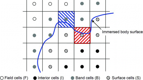
We develop an extension of our original cell classification procedure (Choi et al. Citation2007) to account for the surface cells that act as reservoirs for the mass deposited onto the embedded surface. The Heaviside function ![]() is defined as zero for all field cells (
is defined as zero for all field cells (![]() ) and one for all other cells (). We introduce a new indicating function
) and one for all other cells (). We introduce a new indicating function ![]() to facilitate the classification of surface cells (
to facilitate the classification of surface cells (![]() ), which can act as reservoirs for the particle mass deposited onto the surfaces. Similarly, the Heaviside function
), which can act as reservoirs for the particle mass deposited onto the surfaces. Similarly, the Heaviside function ![]() is defined to be one for the cells just inside the immersed body and is zero otherwise. The calculation of the Heaviside function is initiated by first initializing
is defined to be one for the cells just inside the immersed body and is zero otherwise. The calculation of the Heaviside function is initiated by first initializing ![]() for all points
for all points ![]() . Then, if
. Then, if ![]() and if any
and if any ![]() , where
, where ![]() is a nearest neighbor of a computational cell
is a nearest neighbor of a computational cell ![]() , then
, then ![]() is set to one. Classification of all cells can be summarized as follows:
is set to one. Classification of all cells can be summarized as follows:
where ![]() and
and ![]() represents the set of band and interior cells shown as the gray and closed circles in , respectively.
represents the set of band and interior cells shown as the gray and closed circles in , respectively.
Virtual Mass Transport
The present numerical method for particle transport is based on an Eulerian framework. When an immersed body is moving, nonnegligible mass losses and false dispersion of surface mass distributions at the surface cells can occur. To avoid undesirable numerical problems, we have developed a Lagrangian/Eulerian data transfer algorithm for modeling the virtual mass transport in Equation (1). Note that virtual mass transport corresponds to data (e.g., particle mass) transfer between two different data storages such as Lagrangian surface points and Eulerian surface cells. shows illustrations of the mass transfer between the Lagrangian and the Eulerian framework. Particle mass distributions on the immersed surface are stored at the Lagrangian points followed by the immersed body motion. For a given Lagrangian point ![]() on the immersed surface, we can find the nearest surface cell
on the immersed surface, we can find the nearest surface cell ![]() . Note that
. Note that ![]() and
and ![]() represent the set of Lagrangian points and Eulerian surface cells, respectively. On the basis of the mapping from Lagrangian points to Eulerian surface cells, the mass (
represent the set of Lagrangian points and Eulerian surface cells, respectively. On the basis of the mapping from Lagrangian points to Eulerian surface cells, the mass (![]() ) at the surface cells can be defined as the sums of the mass (
) at the surface cells can be defined as the sums of the mass (![]() ) at the corresponding Lagrangian points:
) at the corresponding Lagrangian points: ![]() for
for ![]() . Particle re-suspension and deposition of mass into and out of these surface cells are then calculated during a computational time step through the solution of Equations (1) and (2).
. Particle re-suspension and deposition of mass into and out of these surface cells are then calculated during a computational time step through the solution of Equations (1) and (2).
FIG. 2 Illustrations of surface mass transfer (a) from Lagrangian to Eulerian data and (b) Eulerian to Lagrangian data. (Color figure available online.)
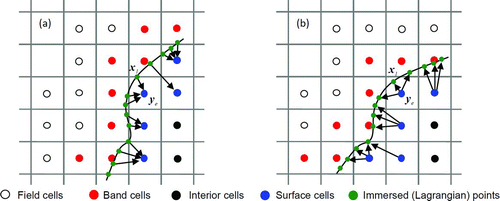
Next, we need to project the mass at the surface cells into the Lagrangian points for the next time level. For a given surface cell ![]() , we can find the Lagrangian points, which have the nearest surface cell
, we can find the Lagrangian points, which have the nearest surface cell ![]() and define a weight function
and define a weight function ![]() based on the inverse of the Euclidean distance. Based on the weight function, the particle mass at the surface cells can be distributed into the Lagrangian points as follows:
based on the inverse of the Euclidean distance. Based on the weight function, the particle mass at the surface cells can be distributed into the Lagrangian points as follows: ![]() for
for ![]() . Here, the weight function is defined as
. Here, the weight function is defined as ![]() .
.
Re-suspension and Deposition Fluxes
The source terms for the cells outside body ![]() and the surface cells
and the surface cells ![]() in Equation (1) can be modeled as
in Equation (1) can be modeled as
To model the re-suspension and deposition fluxes as shown in , we need to estimate the surface mass at the interface between the band and surface cells. For simplicity, the subscript k representing the kth particulate phase is dropped in the following formulation. We assume that surface concentration ![]() at the interfaces, which are adjacent to the band cells, is uniform, with the total mass
at the interfaces, which are adjacent to the band cells, is uniform, with the total mass ![]() at a given surface cell p. We then define an indicator
at a given surface cell p. We then define an indicator ![]() to identify the interface (thick line in ) for the given surface cell p using the Heaviside function
to identify the interface (thick line in ) for the given surface cell p using the Heaviside function ![]() :
: ![]() . Note that
. Note that ![]() , if an interface between the band and surface cells exists; otherwise,
, if an interface between the band and surface cells exists; otherwise, ![]() . Therefore, the surface concentration at the surface cell can be defined as
. Therefore, the surface concentration at the surface cell can be defined as ![]() , where
, where ![]() is the surface area of the interface between cells p and q. A volumetric mass concentration at the interface is approximated as
is the surface area of the interface between cells p and q. A volumetric mass concentration at the interface is approximated as ![]() by assuming that the particles are distributed in a monolayer.
by assuming that the particles are distributed in a monolayer.
FIG. 3 Illustrations of (a) re-suspension and (b) deposition fluxes at the interface. Thick line indicates the interface between the band and surface cells. (Color figure available online.)
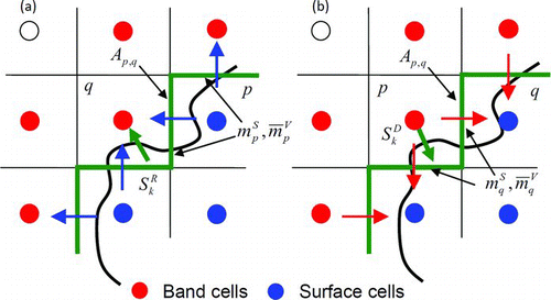
Now, we can formulate a total rate of mass re-suspended from the surface cell p into the adjacent band cells q as
For the deposition rate, the mass flux from the band cell p to its face-neighbor surface cell q is modeled as a combination of Brownian diffusion, gravitational settling, and convective transport normal to the surface:
Here, ![]() is a volume concentration at the band cell p and
is a volume concentration at the band cell p and ![]() is an averaged volume concentration:
is an averaged volume concentration: ![]() . The total deposition rate from the band cell p into the adjacent surface cells q can be defined as
. The total deposition rate from the band cell p into the adjacent surface cells q can be defined as
When a moving surface contacts a substrate, particles in the substrate may attach to the surface. For the particle attachment due to the contact, we assume that the mass in cells representing substrates, where the particle mass is initially partitioned (termed floor cells), is completely transferred into the surface cells representing the reservoirs for the moving surface, when these surface cells occupy the floor cells. After the moving surface is dislodged from a floor cell, the mass in the surface cell representing the surface is equally partitioned compared with the floor cell.
RE-SUSPENSION MODEL
Re-suspension processes are dependent on a number of factors, such as turbulence-induced drag and lift forces, friction forces, gravitational forces, moments induced by these forces (Reeks and Hall Citation2001; Ibrahim et al. Citation2003), and properties of the substrate (asperity distributions). Some researchers (Ziskind et al. Citation1995) have attempted to explain particle re-suspension based on a force imbalance due to turbulent bursts. Other researchers (Reeks et al. Citation1988; Biasi et al. Citation2001; Reeks and Hall Citation2001; Ibrahim et al. Citation2008) have argued that the moments induced on surface asperities ![]() by instantaneous lift/drag forces (rolling mode) are a more probable mechanism for re-suspension, particularly the short-term variant.
by instantaneous lift/drag forces (rolling mode) are a more probable mechanism for re-suspension, particularly the short-term variant.
We consider the dynamic re-suspension model of Reeks and coworkers (Biasi et al. Citation2001), as shown in . The re-suspension rate constant with a Gaussian assumption can be formulated as
FIG. 4 Schematic of particle–substrate contact for the dynamic re-suspension model (Biasi et al. Citation2001).
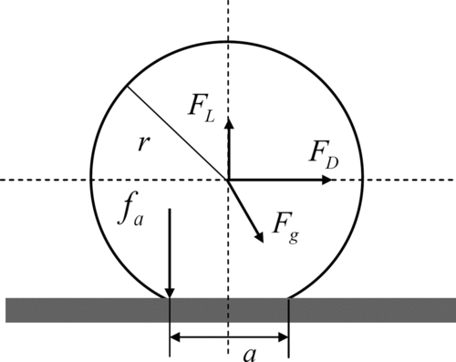
where ![]() is the adhesive force at the point of removal,
is the adhesive force at the point of removal, ![]() and
and ![]() are the mean and fluctuating components of an aerodynamic force
are the mean and fluctuating components of an aerodynamic force ![]() , and
, and ![]() is a typical frequency of the forcing motion. Note that
is a typical frequency of the forcing motion. Note that ![]() and
and ![]() are the lift and drag forces, respectively. The geometric factor is assumed as
are the lift and drag forces, respectively. The geometric factor is assumed as ![]() , where
, where ![]() is a distance between asperities (Biasi et al. Citation2001). We use the semiempirical formula for the drag and lift forces from Biasi et al. (Citation2001), which is based on those in a turbulent channel flow:
is a distance between asperities (Biasi et al. Citation2001). We use the semiempirical formula for the drag and lift forces from Biasi et al. (Citation2001), which is based on those in a turbulent channel flow:
For a perfectly smooth contact, which is described by the JKR model (Johnson et al. Citation1971), the adhesive force ![]() for a sphere of radius
for a sphere of radius ![]() is given by
is given by
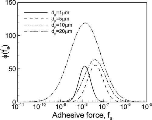
We use the semiempirical correlations for the geometric mean and geometric standard deviation of the normalized adhesive force from Biasi et al. (Citation2001): ![]() and
and ![]() . shows lognormal distributions of the normalized adhesive force for different particle sizes. Although larger particles have a higher mean adhesive force, a larger spread of the distribution is expected with lower levels of the adhesive force. This increases the probability of particle re-suspension for larger particles.
. shows lognormal distributions of the normalized adhesive force for different particle sizes. Although larger particles have a higher mean adhesive force, a larger spread of the distribution is expected with lower levels of the adhesive force. This increases the probability of particle re-suspension for larger particles.
Using the re-suspension rate constant in Equation (9) and distributions of the adhesive force in Equation (13), we can define a re-suspension rate by integration over the possible range of the adhesive forces:
The mass re-suspended can be determined as a convolution integral of the instantaneous re-suspension rate and surface mass; however, it is not trivial to store surface mass distributions and instantaneous re-suspension rates at every time step. Assuming that the mass fractions remaining are sufficiently small, we might approximate the convolution integral within a computational time step ![]() as a product of an averaged re-suspension rate and surface mass, which is the source term representing the re-suspended mass rate in Equation (6). The corresponding averaged re-suspension rate can be defined as
as a product of an averaged re-suspension rate and surface mass, which is the source term representing the re-suspended mass rate in Equation (6). The corresponding averaged re-suspension rate can be defined as
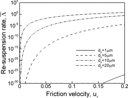
shows the averaged re-suspension rate as a function of the friction velocity for a time interval ![]() s. As expected, the larger particles have higher re-suspension rates, and higher friction velocities increase re-suspension rates. However, the smaller particle (dp
= 1 μm) shows no significant re-suspension rate up to
s. As expected, the larger particles have higher re-suspension rates, and higher friction velocities increase re-suspension rates. However, the smaller particle (dp
= 1 μm) shows no significant re-suspension rate up to ![]() m/s.
m/s.
RESULTS AND DISCUSSION
Problem Definition
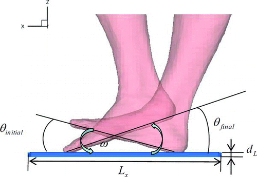
Simulations of particulate flow near a foot during a stepping up–down motion are performed using a foot-floor configuration as sketched in . The foot is rendered as a CAD STL file, which is extracted from a whole-body model (Choi et al. Citation2007) using a segmentation procedure, and is embedded into a computational domain as an immersed object. The foot is 0.25 m long, 0.12 m wide, and its projected area into the floor ![]() is about 0.018 m2. We assumed that the present foot model is static but not flexible. The computational domain is 0.5 m × 0.5 m × 0.3 m with a baseline grid resolution of 121 × 103 × 133 (∼1.6 million cells). The mesh has nonuniform spacing in the horizontal directions and is stretched in the vertical direction to allow a better resolution under the foot. Uniform cells with 1 mm grid spacing are used in the carpet layer, and the maximum vertical grid spacing under the foot is about 3 mm. The motion of foot is simplified as follows. Initially, the toe is lifted from the floor with
is about 0.018 m2. We assumed that the present foot model is static but not flexible. The computational domain is 0.5 m × 0.5 m × 0.3 m with a baseline grid resolution of 121 × 103 × 133 (∼1.6 million cells). The mesh has nonuniform spacing in the horizontal directions and is stretched in the vertical direction to allow a better resolution under the foot. Uniform cells with 1 mm grid spacing are used in the carpet layer, and the maximum vertical grid spacing under the foot is about 3 mm. The motion of foot is simplified as follows. Initially, the toe is lifted from the floor with ![]() , and the angle between the heel and the floor is held at
, and the angle between the heel and the floor is held at ![]() after a complete foot motion with a constant angular velocity
after a complete foot motion with a constant angular velocity ![]() . These parameters describing the foot motion are estimated from the results of Eisner et al. (Citation2010). After the foot motion stops, simulations are continued up to 2.5 s. The computational time step used is 0.001 s. The floor is assumed to be a carpet layer with cross section 0.4 m × 0.4 m and thickness
. These parameters describing the foot motion are estimated from the results of Eisner et al. (Citation2010). After the foot motion stops, simulations are continued up to 2.5 s. The computational time step used is 0.001 s. The floor is assumed to be a carpet layer with cross section 0.4 m × 0.4 m and thickness ![]() . Particles are uniformly distributed in the carpet layer at a surface concentration of
. Particles are uniformly distributed in the carpet layer at a surface concentration of ![]() kg/m2. Four different particle diameters (dp
= 1, 5, 10, and 20 μm) are considered, and the intrinsic density of the particulate is chosen as 2400 kg/m3. Simulations conducted on this configuration vary the thickness of the carpet layer (dL
= 5 and 10 mm), the penetration depth of the foot into the carpet layer (pd
= 1 and 5 mm), and the angular velocity of the foot motion (21°, 28°, and 35°/s; i.e., 0.367, 0.489, and 0.611 rad/s). Cases in the present study are summarized in .
kg/m2. Four different particle diameters (dp
= 1, 5, 10, and 20 μm) are considered, and the intrinsic density of the particulate is chosen as 2400 kg/m3. Simulations conducted on this configuration vary the thickness of the carpet layer (dL
= 5 and 10 mm), the penetration depth of the foot into the carpet layer (pd
= 1 and 5 mm), and the angular velocity of the foot motion (21°, 28°, and 35°/s; i.e., 0.367, 0.489, and 0.611 rad/s). Cases in the present study are summarized in .
TABLE 1 Numerical conditions for particle re-suspension and deposition simulations
Particle Re-suspension Simulations
Initially, particles are uniformly distributed in the carpet layer with specified surface concentrations while background particle concentrations are neglected. We define a volumetric particle concentration in the carpet layer in terms of the thickness of layer, assuming a constant total mass in the layer. When the foot contacts the carpet layer and compresses the floor cells, the mass in the cells is completely transferred into the surface cells representing the reservoirs for the moving foot surface. However, when the foot decompresses the floor cells, the mass in the surface cells is equally partitioned compared with that in the floor cells. As a baseline simulation condition, we consider that the thickness of the floor layer is 10 mm, the foot is allowed to penetrate into the layer up to 5 mm, and the angular velocity of the foot motion is 28°/s.
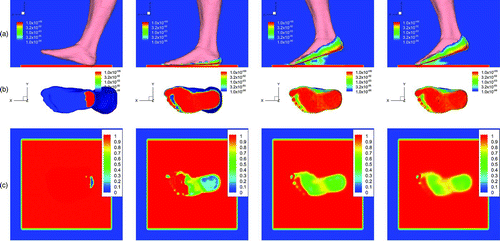
shows snapshots of particle concentrations on the foot and floor surfaces (at 7.5 mm from the bottom—this is the half position of the foot penetration depth) as well as airborne particle concentrations at a vertical plane (near the symmetry plane) for four different time instances. Note that the particle diameter is 10 μm. Except for particle concentrations at the floor surface, the concentrations are shown in a logarithmic scale. Initially, particles accumulate near the heel region because of the foot's contact with the floor surface. When the foot completely contacts the floor surface, particle deposition onto the bottom surface of the foot takes place, and a footprint on the floor surface is clearly observed. After the foot lifts off, the particle concentrations on the foot surface are distributed over a wide region of the surface. A cloud of re-suspended particles beneath the foot surface is formed and the cloud moves toward the toe as more time elapses. This evolution of the particle cloud is similar to the experimental finding in Eisner et al. (Citation2010).
FIG. 8 Particle concentrations (a) at the foot surface and in the ambient air, (b) at the foot bottom surface, and (c) the floor (carpet layer) surface for four different time instances. The particle diameter is 10 μm. (Color figure available online.)
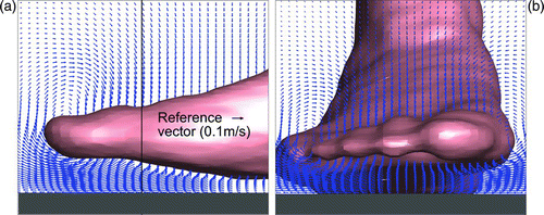
To see transient dynamics of the re-suspended particles near the foot in detail, we investigate the velocity fields at four different time instances. shows the velocity fields at a vertical plane (near the symmetry plane) and a cross-sectional plane near the toe region when the toe is stepping down (t = 0.3 s). As expected, a squeezing flow pattern is clearly observed under the foot while strong circulating flows occur near the edges of the foot (e.g., toe and the sides of the foot). The squeezing flow may induce particle re-suspension from the floor surface. Unexpectedly, no significant particle re-suspension is found during the toe stepping-down cycle. One explanation might be that the re-suspended particles beneath the foot surface may redeposit onto the foot surface during the toe stepping-down cycle. It is also possible that the particles move toward the carpet due to inertia and gravity effects while surrounding air is being pushed into the carpet layer by the action of the foot.
FIG. 9 Velocity fields (a) at a vertical plane (near the symmetry plane) and (b) at a cross-sectional plane near the toe region during a toe stepping-down cycle (at t = 0.3 s). (Color figure available online.)
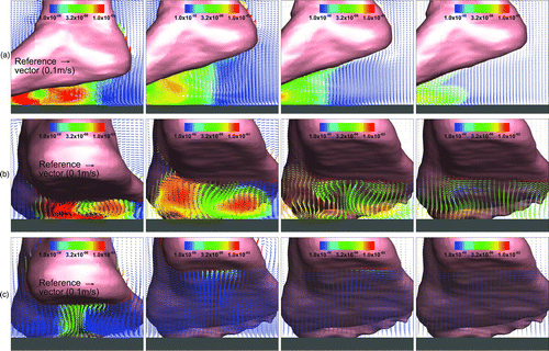
Next, we investigate the velocity fields at a vertical plane (near the symmetry plane) and two cross-sectional planes near the center and heel regions after the foot lifts off (t = 0.9 s), just before the foot stops (t = 1.2 s), after the foot has stopped (t = 1.5 s), and after more time elapses (t = 2.5 s). In , the velocity vectors are colored by the concentration levels of particles whose diameters are 10 μm in a logarithmic scale. The entrainment of air into a gap between the foot and the floor is clearly observed, and particles ejected from the floor surface move toward the toe region. The heel stepping-up motion induces a pair of strong counter-rotating vortices shown in cross-sectional planes, and the vortices promote particle accumulation near the foot surface. As more time elapses, the pairs of vortices and the counter-clockwise vortex weaken. Particles may move downward under the influences of the vortex pairs and gravity, while the re-suspended particles form a cloud and continue to move toward the toe region. Compared with the experimental results of Eisner et al. (Citation2010), particle re-suspension is observed along a wider region of the foot bottom surface when the foot starts lifting off. This is because the particles are more widely deposited onto the foot surface due to the initial contact with the floor. The cloud of particles near the foot as shown in the experimental images is observed in the simulation results, and the re-suspended particles move toward the toe, similar to the experimental finding.
FIG. 10 Velocity fields (a) at a vertical plane (near the symmetry plane), (b) at a cross-sectional plane near the centerline of the foot, and (c) at a cross-sectional plane near the heel region for four different time instances. Colors represent the levels of particle concentrations (dp = 10 μm). (Color figure available online.)
Particle Re-suspension Data Analysis
Before proceeding with further analysis of particle re-suspension data, we perform a sensitivity analysis that varies the grid resolution and the computational time step. We consider four levels of grid resolution with spacings in the wall-transverse directions of roughly 8, 4, 2, and 1.5 mm under the foot. The total numbers of grid cells are about 0.5, 1.6, 4.6, and 7.5 million, respectively. We also consider three computational time steps: 0.01, 0.001, and 0.0005 s.
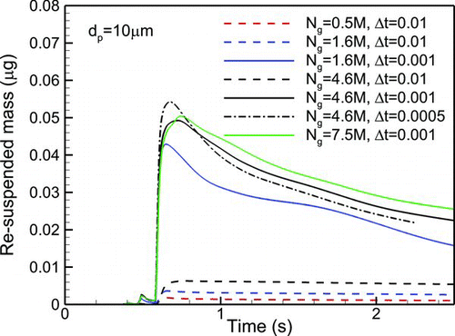
To assess the sensitivity of the computed flow field to the computational parameters varied (mesh size and time step), we monitored the maximum friction velocities on the foot and floor surfaces, as shown in . This is because a friction velocity is the dominant factor in characterizing a local re-suspension rate. The maximum friction velocities over the foot and floor surfaces increase during a toe stepping-down cycle (t < 0.5 s). After the foot lifts off, the friction velocity sharply increases within a short time (t ∼ 0.6 s). As more time elapses, the maximum friction velocities decrease for both surfaces. The evolution of the friction velocity is not especially sensitive to the computational parameters; however, the peak values are higher for finer grid resolutions and smaller time steps. Considering the 4 mm mesh resolution with 0.001 s time step as a baseline result, we find about a 2% difference in the peak value for the case with 2 mm mesh resolution and 0.001 s time step. This indicates that the baseline parameters adequately resolve footstep-induced flows, but it should be remarked that the maximum friction velocity in the case of 2 mm mesh resolution is slightly higher than that in the baseline case during a heel stepping-up cycle. shows the sensitivity of particle re-suspension to the varied computational parameters. Here, we presented the re-suspended mass for particles whose diameters are 10 μm. The peak value of the re-suspended mass in the baseline case is about 18% smaller than that in the case of the finest 1.5 mm mesh resolution. This may be attributed to the fact that for dp = 10 μm size particles, the local re-suspension rate increases by the factor of 1.17 for a 2% increase in the friction velocity near 0.1 m/s, as shown in . This implies that the modeled particle re-suspension process is more sensitive to the spatial and temporal resolutions than is the calculation of the carrier-gas flow field.
FIG. 11 The effect of the spatial and temporal resolutions on the maximum friction velocity on (a) foot surface and (b) floor. (Color figure available online.)
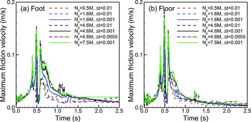
FIG. 12 The effects of grid resolutions and computational time steps on the re-suspended mass for particles whose diameters are 10 μm. (Color figure available online.)
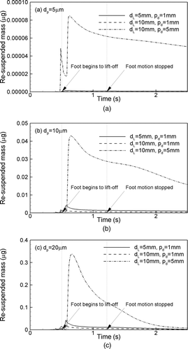
Next, we perform a parametric study to identify the effects of particle sizes, floor conditions, and the angular velocity of the foot motion on particle re-suspension. Note that for the smallest particle size (1 μm) considered in the present study, the amount of re-suspension is almost negligible, and this case is excluded in the remainder of the analysis. shows the effect of particle sizes on the mass of the re-suspended particles during a footstep for different thicknesses of the carpet layer and the foot penetration depths. The angular velocity of the foot motion is 28°/s. Before the foot completely contacts with the floor (at ∼0.6 s), no significant mass is re-suspended. This may be due to the fact that the particles are immediately redeposited onto the floor cells and particle re-suspension itself is small, as discussed in the previous section. Once some portions of the foot surface begin to escape from the carpet layer, the re-suspended mass rapidly increases. Generally, the larger particles are more re-suspended into the ambient air during the foot lifting-off period. After the foot motion stops, the re-suspended mass for large particles decreases as the particles are redeposited onto the floor surface due to gravitational settling. For a given penetration depth (pd = 1 mm), the mass re-suspended increases for a thinner carpet layer. A deeper foot penetration for the same thickness of the carpet layer (dL = 10 mm) also increases the mass re-suspended, which is consistent with the results in Oberoi et al. (Citation2010).
FIG. 13 The effects of the thickness of the carpet layer and the penetration depth on the re-suspended mass for each case: (a) dp = 5 μm, (b) dp = 10 μm, and (c) dp = 20 μm.
Now, we consider the maximum mass re-suspended into the ambient air (MR ) and deposited onto the foot surface (MF ), which are summarized in for each case. Both MR and MF apparently increase for a deeper penetration and a thinner carpet layer. Recall that particles are uniformly distributed in the carpet layer at the initial stage. The actual mass of the particles in the carpet layer that are directly able to contact with the foot surface during the foot motion may depend on the thickness of the carpet layer and the foot penetration depth. To assess this effect on the re-suspension process, we introduce the maximum mass compressed (MC ) due to the foot motion in the carpet layer. This can be estimated as
TABLE 2 Maximum re-suspended mass in the ambient air and deposited mass onto the foot
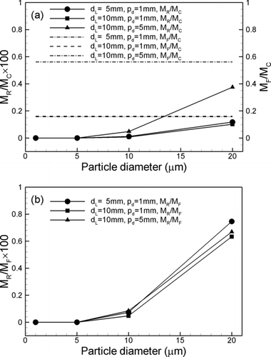
shows the mass re-suspended (MR ) and deposited onto the foot (MF ) normalized by the maximum mass compressed (MC ) for different particle sizes in three cases. Note that MR /MC represents a re-suspension fraction. For the shallow (pd = 1 mm) and deep penetration (pd = 5 mm), about 16% and 55% of MC are deposited onto the foot surface during a footstep, respectively, while less than 0.43% of MC is re-suspended and MR /MC in the deep penetration is about 40 times larger than that in the shallow penetration for the largest particles. The scaling based on MC shows a good correlation of MR and MF with the thickness of the carpet layer, but not with the penetration depth. This implies that a deeper foot penetration increases more mass transfer from the carpet layer to the foot and to the ambient air because the contact time of the foot surface with the carpet layer is increased. We also consider a scaling of the mass re-suspended (MR ) with the mass deposited onto the foot MF as shown in . The scaling based on MF shows a fairly good correlation of MR with the thickness of the carpet layer and the penetration depth, but a mild deviation of the correlation is found for the largest particles.
FIG. 14 The effects of the thickness of the carpet layer and the penetration depth on maximum re-suspended mass in the ambient air and deposited onto the foot: (a) normalization with maximum compressed mass and (b) maximum deposited mass onto the foot.
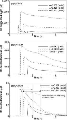
We also investigate the effect of the angular velocity of the foot motion on the re-suspended mass for different particle sizes in . Three different angular velocities are considered: 21°, 28°, and 35°/s; i.e., 0.367, 0.489, and 0.611 rad/s. Time intervals for the heel stepping-up cycle are marked in . General trends are that the larger particles are more re-suspended during the cycle regardless of the foot speed. Once the foot lifts off, the re-suspended mass rapidly increases, and maximum re-suspension for all of the particle sizes is found within the cycle. As expected, the faster foot motion increases the re-suspended mass because the forcing frequency and probability of the particle re-suspension in the rate expression both increase due to a higher friction velocity.
FIG. 15 The effect of the angular velocity on the re-suspended mass for different particle diameters.
To quantify the re-suspension during a footstep, we consider an instantaneous re-suspension rate (R) defined as
TABLE 3 Peak and mean re-suspension rates, Rpeak and Rmean (s−1), during a footstep
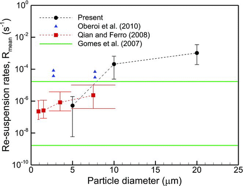
shows a comparison of the predicted re-suspension rates for different particle sizes with those in experiments (Gomes et al. Citation2007; Qian and Ferro Citation2008) and the numerical simulation (Oberoi et al. Citation2010). Recent experiments showed that average re-suspension rates ranged from 10–5 to 10–2 h–1 [2.8 × 10⁻⁹ to 2.8 × 10⁻⁶ s–1] for particle sizes of 0.8–10 μm in Qian and Ferro (Citation2008), while the rates ranged from 10–7 to 10–3 min–1 [1.7 × 10⁻⁹ to 1.7 × 10⁻⁵ s–1] for particle sizes over 2 μm in Gomes et al. (Citation2007). The re-suspension rates in the experiments with a time scale of 1 h or 1 min are simply converted to the rates in 1 s, ignoring the sensitivity issue on the sampling related to a time scale of events (Gomes et al. Citation2007; Oberoi et al. Citation2010). Previous numerical simulations in Oberoi et al. (Citation2010) showed that the predicted re-suspension rates ranged from 3.7 × 10⁻⁵ to 8.1 × 10⁻⁵ s–1 for two size classes of particles (2.7 and 7.7 μm). Error bars for the present simulation indicate maximum or minimum of re-suspension rates while error bars for Qian and Ferro (Citation2008) indicate 10 and 90 percentiles of their experimental results. For Gomes et al. (Citation2007), the upper and lower bounds of the averaged re-suspended rates are plotted. The predicted re-suspension rates are, in general, overestimated by at most one order of magnitude compared with the experiments. Peak re-suspension rates are one order of magnitude higher than average re-suspension rates, which is consistent with the findings in Gomes et al. (Citation2007). The present results show that larger particles in a size range of 1–20 μm have higher re-suspension rates.
The difference in re-suspension rates between the present simulation and the experiments might be due to the following facts. First, we consider a short-time re-suspension event over a few seconds, while the experiments consider 30 min of person activity, including walking, sitting, tapping, and body movements in Qian and Ferro (Citation2008). Thus, serial footsteps, wake interference induced by the body movements, and periods of time without activity may reduce overall re-suspension rates. Second, the definition of reference mass for floor conditions used in the simulation is different from that in the experiments. In order to highlight a transient response due to a footstep, the predictions of re-suspension rates are based on an effective volume in defining the initial mass in terms of a penetration depth and the projected area of the foot into the carpet layer. However, the reference mass in the experiments was estimated from a much larger test flooring area where a person walked and moved. Third, as reported by Gomes et al. (Citation2007), instantaneous re-suspension rates based on a 1-s sampling period were, in general, 10–100 times higher than their respective average rates based on 1 min. Owing to the limitations of the present simulation, which focused on a single footstep event (∼1 s), we used a 0.001-s sampling period while Qian and Ferro (Citation2008) used 6 s.
CONCLUSIONS
A large eddy simulation or an immersed boundary method for simulating particulate flows has been applied to investigate a short-term particle re-suspension from the carpet layer during a footstep. A dynamic re-suspension model is used for particle detachment due to the foot motions, while a model accounting for Brownian diffusion, gravitational settling, and convective impaction is used for particle deposition. Fine-scale, transient simulations of particle re-suspension during a footstep are performed, with various environmental factors such as different floor conditions, walking speed, and particles sizes.
During a toe stepping-down motion, no significant particle re-suspension is observed, but a squeezing flow pattern under the foot and strong circulating flows near the edges of the foot are clearly captured. When the foot completely contacts with the carpet layer, deposition beneath the foot surface is captured while a footprint is clearly seen after the foot lifts up. During a heel stepping-up cycle, airflow entrained into a region beneath the foot promotes movements of particles near the heel toward the toe region while a pair of strong counter-rotating vortices enhances particle deposition onto the foot surface. As more time elapses after the foot stops, vortices induced by the foot motion are weakened, particles fall down due to gravity effects, and re-suspended particles continue to move toward the toe region due to residual velocity fluctuations, similar to the experimental findings in Eisner et al. (Citation2010).
Parametric studies show that a deeper foot penetration into a thinner carpet layer increases the mass re-suspended due to a more compressed volume by the foot motion. A faster foot motion increases the mass re-suspended due to higher forcing frequency and re-suspension probability. For particles with a size range of 1–20 μm, the larger particles have higher re-suspension rates. General trends of the re-suspension rates are consistent with other experimental findings (Gomes et al. Citation2007; Qian and Ferro Citation2008), but the predicted re-suspension rates are overestimated by at most one order of magnitude compared with the experiments. This may be attributed to the facts such as (1) a single footstep versus serial footsteps and other human activities, (2) a confined floor area near the foot versus a test flooring area for initial mass loading, and (3) a short sampling period.
Acknowledgments
This work has been sponsored by the US Environmental Protection Agency under contracts 3C-R310-NTEX and 4C-R138-NAEX. The first author is currently supported by WCU (World Class University) program through the National Research Foundation of Korea (NRF) funded by the Ministry of Education, Science and Technology R31-10049. Computer resources were provided by the High Performance Computing component of North Carolina State University's Information Technology Division (http://www.ncsu.edu/itd/hpc).
Disclaimer: The views expressed in this article are those of the authors and do not necessarily reflect the views or policies of the US Environmental Protection Agency.
REFERENCES
- Biasi , L. , de los Reyes , A. , Reeks , M. W. and de Santi , G. F. 2001 . Use of a Simple Model for the Interpretation of Experimental Data on Particle Re-suspension in Turbulent Flows . J. Aerosol Sci. , 32 : 1175 – 1200 .
- Choi , J.-I. and Edwards , J. R. 2008 . Large Eddy Simulation and Zonal Modeling of Human-Induced Contaminant Transport . Indoor Air , 18 : 233 – 249 .
- Choi , J.-I. and Edwards , J. R. 2012 . Large Eddy Simulation of Human-Induced Contaminant Transport in Room Compartments . Indoor Air , DOI: 10.1111/j.1600-0668.2011.00741.x
- Choi , J.-I. , Oberoi , R. C. , Edwards , J. R. and Rosati , J. A. 2007 . An Immersed Boundary Method for Complex Incompressible Flows . J. Comput. Phys. , 224 : 757 – 784 .
- Cicciarelli , B. A. , Davidson , D. L. , Hart , E. H. and Peoples , P. R. CFD Analysis of the Behavior of Airborne Allergens in Carpeted and Uncarpeted Dwellings . Proceedings of the 2002 ASME Pressure Vessels and Piping Conference, 2002–1557 . Vancouver , British Columbia, Canada.
- Eisner , A. D. , Rosati , J. and Wiener , R. 2010 . Experimental and Theoretical Investigation of Particle-Laden Airflow Under a Prosthetic Mechanical Foot in Motion . Build. Environ. , 4 : 878 – 886 .
- Ferro , A. R. , Kopperud , R. J. and Hildemann , L. M. 2004 . Source Strengths for Indoor Human Activities That Re-suspended Particulate Matter . Environ. Sci. Technol. , 38 : 1759 – 1764 .
- Gomes , C. , Freihaut , J. and Bahnfleth , W. 2007 . Re-suspension of Allergen-Containing Particles Under Mechanical and Aerodynamic Disturbances from Human Walking . Atmos. Environ. , 41 : 5257 – 5270 .
- Hall , D. 1988 . Measurement of the Mean Lift Force on a Particle near a Boundary Layer in Turbulent Flow . J. Fluid Mech. , 187 : 451 – 466 .
- Hu , B. , Freihaut , J. D. , Bahnfleth , W. P. , Aumpansub , P. and Thran , B. 2007 . Modeling Particle Dispersion Under Human Activity Disturbance in a Multizone Indoor Environment . ASCE—J. Arch. Eng. , 13 ( 4 ) : 187 – 193 .
- Ibrahim , A. H. , Dunn , P. F. and Brach , R. M. 2003 . Microparticle Detachment from Surfaces Exposed to Turbulent Air Flow: Controlled Experiment and Modeling . J. Aerosol Sci. , 34 : 765 – 782 .
- Ibrahim , A. H. , Dunn , P. F. and Qazi , M. F. 2008 . Experiment and Validation of a Model for Microparticle Detachment from a Surface by Turbulent Air Flow . J. Aerosol Sci. , 39 : 645 – 656 .
- Johnson , K. L. , Kendall , K. and Roberts , A. D. 1971 . Surface Energy and Contact of Elastic Solids . Proc. R. Soc. Lond. A Math. Phys. Sci. , 324 : 301 – 313 .
- Karlsson , E. , Berglund , T. , Strömqvist , M. , Nordstrand , M. and Fängmark , I. 1999 . The Effect of Re-suspension Caused by Human Activities on the Indoor Concentration of Biological Aerosols . J. Aerosol Sci. , 30 ( S1 ) : S737 – S738 .
- Karlsson , E. , Fängmark , I. and Berglund , T. 1996 . Re-suspension of an Indoor Aerosol . J. Aerosol Sci. , 27 ( S1 ) : S441 – S442 .
- Nazaroff , W. W. 2004 . Indoor Particle Dynamics . Indoor Air , 14 ( S7 ) : 175 – 183 .
- Oberoi , R. C. , Choi , J.-I. , Edwards , J. R. , Rosati , J. A. , Thornburg , J. and Rodes , C. 2010 . Human-Induced Particle Re-suspension in a Room . Aerosol Sci. Technol. , 44 : 216 – 229 .
- Qian , J. and Ferro , A. R. 2008 . Re-suspension of Dust Particles in a Chamber and Associated Environmental Factors . Aerosol Sci. Technol. , 42 : 566 – 578 .
- Reeks , M. W. and Hall , D. 2001 . Kinetic Models for Particle Re-suspension in Turbulent Flows: Theory and Measurement . J. Aerosol Sci. , 32 : 1 – 31 .
- Reeks , M. W. , Reed , J. and Hall , D. 1988 . On the Re-suspension of Small Particles by a Turbulent Flow . J. Phys. D Appl. Phys. , 21 : 474 – 489 .
- Rosati , J. A. , Thornburg , J. and Rodes , C. 2008 . Re-suspension of Particulate Matter from Carpet due to Human Activity . Aerosol Sci. Technol. , 42 : 472 – 482 .
- Thatcher , T. L. and Layton , D. W. 1995 . Deposition, Re-suspension, and Penetration of Particles Within a Residence . Atmos. Environ. , 29 : 1487 – 1497 .
- Zhang , X. Y. , Ahmadi , G. , Qian , J. and Ferro , A. 2008 . Particle Detachment, Re-suspension and Transport due to Human Walking in Indoor Environments . J. Adhes. Sci. Technol. , 22 : 591 – 621 .
- Ziskind , G. , Fichman , M. and Gutfinger , C. 1995 . Re-suspension of Particulates from Surfaces to Turbulent Flows—Review and Analysis . J. Aerosol Sci. , 26 : 613 – 644 .
