Abstract
Two-component model aerosols consisting of KCl vapor and ultrafine K2SO4 particles were generated in the laboratory to study sample behavior in a high-temperature porous tube sampling probe. The conditions were set to represent those typically occurring at biomass-fired furnaces. Particle size distributions were measured from the diluted aerosol via several sampling parameters and the temperature and mixing conditions inside the diluting probe were characterized. The experimental findings were interpreted by one-dimensional aerosol dynamics modeling. Gaseous KCl was found to form very small KCl particles inside the diluter by homogeneous nucleation. In the cases where K2SO4 seed particles were introduced into the sample, part of the KCl vapor condensed on the seeds, while the remainder formed a clearly distinct nucleation mode due to the relatively high cooling rates in the probe. In the studied probe, mixing of sample and dilution gas was relatively fast, which was found to be favorable for KCl nucleation. The condensation behavior of KCl in the probe with simultaneous dilution and cooling was found to be clearly influenced by mixing, cooling, and surface area of the existing particles. The results show that in the porous tube diluter, different sampling parameters can be used either to enhance the appearance of nucleation mode, or to promote condensation of vapors on existing particles to minimize sample losses on walls. Furthermore, these results point to the possibility to design a high-temperature sampling system, which minimizes the artifacts caused by vapor condensation on existing fine particles during sampling.
Copyright 2012 American Association for Aerosol Research
INTRODUCTION
Measurements of aerosols at high temperatures are required under several situations (e.g., in studies focusing on ash behavior and emission formation in combustion processes). The formation of ash aerosols, consisting of condensing vapors and fine fly ash particles, is a major problem in biomass-fired boilers since they cause fouling, corrosion of heat exchanger tubes, and often high fine particle emissions (Michelsen et al. Citation1998; Van Loo and Koppejan Citation2008). These disadvantages are usually related to vaporization of alkali metal-containing species from the fuel that exists in the furnace both in gaseous and particulate form, depending on their chemical form (mainly sulfates, chlorides, hydroxides, carbonates, and phosphates) and prevailing temperatures (Christensen et al. Citation1998; Valmari et al. Citation1998; Sippula et al. Citation2007; Tissari et al. Citation2008). In efficient biomass combustion processes, such as large-scale boilers and modern small-scale systems, alkali metal species are the main constituents of fine particles (Valmari et al. Citation1998; Sippula et al. Citation2007, Citation2009a). According to current understanding, the gas-to-particle conversion of alkali metals in hot flue gas (with most of the biomasses) occurs by a gas-phase alkali metal sulfation reaction in a temperature interval of 800–1200°C (Baxter et al. Citation1998; Christensen et al. Citation1998; Sippula et al. Citation2008). This is followed by gas-to-particle conversion of alkali carbonates (if any) and by alkali chlorides (Valmari et al. Citation1998). In general, the particle emissions from combustion processes exist in a bimodal size distribution (Christensen et al. Citation1998; Sippula et al. Citation2009b) with modes having distinctly different chemical compositions. However, occasionally, an additional feature is observed when the sampling is carried out at high temperatures (>500°C) with a diluting sampling probe. Several studies have reported about an additional mode consisting of nanoparticles, which are apparently created from vapor-phase alkali species by nucleation during dilution of the sample (Strand et al. Citation2004; Johansson et al. Citation2008; Jimenez and Ballester Citation2011). This mode is referred to as the nucleation mode. Particularly in combustion of biomasses with high chlorine contents, large fractions of alkali chloride vapors can be expected in the postcombustion zone. The sampling from these conditions may be challenging since the condensing vapors may easily cause sample losses and a biased sample.
In general, the detailed measurements of particle concentrations, size distributions, chemical compositions, and vapor-particle distributions in a hot environment require either in situ measurement methods (e.g., optical spectroscopy based methods) or a reliable sampling system. One example of a common in situ method is the opacity monitor, which is commonly used to monitor dust concentrations in flue gases of combustion plants. However, at present, the most reliable particle analysis and measurement methods applicable for real-world processes are sampling based methods. In general, there are two different approaches for high-temperature sampling and measurement of aerosols. First, measurement or collection of the sample for offline analysis can be made in the same or similar conditions as in the process. There are several examples of this type of method, e.g., high-temperature impactors, which can be used in the furnace for collection of size-segregated particle samples (Valmari et al. Citation1999b; Obernberger et al. Citation2009) and simple particle collections on filters by in-stack or out-stack methods with heated sampling line and filter base (Valmari et al. Citation1999a). The advantage of these methods is that in ideal cases no changes should occur in the sample. However, the instruments have to be able to operate under harsh conditions, which preclude the use of many measurement technologies. The second approach is to dilute and cool the sample so that it is suitable for the aerosol measurement devices. The aims of these sampling systems may be either to measure the total particulate matter in the hot gas, including also the vapor-phase precursors, or to quench the sample in order to freeze the chemical reactions and aerosol dynamics and thus to obtain information on the particles and vapors present at the sampling location. The advantages of these sampling systems are the possibilities to use several measurement and analysis techniques that can be operated only close to ambient temperatures. However, significant changes in the sample may occur due to losses and transformation of the sample. First, cool surfaces easily cause high losses due to the thermophoresis that drives vapors and particles of all sizes on cold surfaces (Mikkanen et al. Citation1999; Brockmann Citation2001). Second, for nanoparticles, the diffusion losses can be considerable if sampling lines are long or when particles are very small (DP < 10 nm) (Brockmann Citation2001). Third, the condensation of vapors may change the properties of particles and their distribution and often the particulate and vapor-phase species become mixed in the sampling system.
There are several different designs of diluting sampling probes including axial diluters (Mikkanen et al. Citation1999), porous tube diluters (Lyyränen et al. Citation2004; Tissari et al. Citation2008; Sippula, Hokkinen, et al. Citation2009a; Deuerling et al. Citation2010), perforated tube diluters (Pyykönen et al. Citation2007), and ejector diluters (Lyyränen et al. Citation2004). In addition, an aerodynamic quench probe has been utilized for high-temperature aerosol sampling, which instead of diluting the sample expands it in a vacuum in order to cool the sample rapidly (Jimenez and Ballester Citation2005). A high-temperature sampling system may either promote the nucleation of condensable vapors, resulting in a separation of particulate and vapor-phase species, or favor the condensation of vapors on existing particles (Jimenez and Ballester Citation2005). The first of these sampling systems is optimal for studies on particle formation mechanisms, while the latter sampling conditions are appropriate for measurements aimed at measuring the total particulate forming material, e.g., these may be needed when deposition over heat exchangers or the efficiencies of particle precipitators need to be measured, since the nucleated particles easily become lost in the sampling lines by diffusion. Thus, depending on the aims of the study, different sampling conditions are needed. The essential parameters affecting the vapor behavior and aerosol dynamics in the sampling system are the dilution ratios (DRs), mixing conditions, temperatures, cooling rates, and sample properties such as particle surface area and vapor pressures of condensable species. However, at present, only very few systematic studies (Strand et al. Citation2004) exist on the effect of these parameters in high-temperature furnace sampling.
The behavior of vapor-phase species has been shown to be largely affected by the sample DR used in the high-temperature probe. Sippula et al. (Citation2008) carried out sampling of aerosols with a porous tube quench-probe at around 850°C from a pulverized wood combustion reactor. The measured particle size distributions in the ultrafine particle region were found to be very sensitive to the chosen DR in the probe such that an increase in the DR was found to result in higher number concentrations and smaller particles. Strand et al. (Citation2004) studied the behavior of KCl vapor in a diluting probe with a model aerosol consisting of KCl vapor and SiO2 particles. The sampling was carried out at 900°C. With a DR of 10, the KCl vapor was found to create a distinct nucleation mode, whereas there was only a minor condensation of KCl on SiO2 particles. Increasing the DR decreased the presence of KCl in the nucleation mode, and with a DR of 100, no KCl was found. The authors postulated that this was either related to efficient wall losses in the probe, formation of nucleation mode particles below 10 nm, which could not be detected with the applied instruments, or by both of these mechanisms. The effects of DR have been also studied in low-temperature sampling systems, revealing also the significant effect of the DR on the formation and size distributions of ultrafine particles formed of vapor-phase precursors (Kittelsson 1998; Lipsky et al. Citation2002, Citation2004; Pyykönen et al. Citation2007). Finally, Jimenez and Ballester (Citation2005) compared an aerodynamic quench probe and a diluting probe for high-temperature sampling of aerosols from pulverized biomass combustion. The aerodynamic probe was found to generate a nucleation of vapor-phase alkali species, which consequently prevented their condensation on fine particles in the sample. Good separation was likely to be achieved by adiabatic expansion, which resulted in a very high cooling rate (∼108°C/s) at the probe inlet. In contrast, in the diluting probe, the cooling rate was several orders of magnitude lower and this was found to promote the condensation of vapors on existing particles in the probe. Overall, the interpretation of the effects of various sampling conditions on the sample transformation is very complicated, since very seldom it is possible to change only one parameter. For example, a change in DR affects both coagulation and gas-to-particle conversion and it simultaneously changes the sample temperatures and concentrations along the probe.
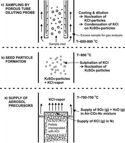
FIG. 2 Scheme of supply system for (a) aerosol precursors, (b) seed particle generation, and (c) aerosol sampling.
The aim of this study was to characterize factors affecting aerosol transformation in a high-temperature diluting sampling system, focusing especially on the conditions typically encountered in biomass-fired boilers and in the superheater area. Thus, the study focused on the behavior of alkali metal aerosols inside the high-temperature sampling system. One practical aspect was to find out optimal sampling parameters and to obtain a better understanding of the results gathered in real combustion measurements. Second, the aim was to obtain more information for the development of more advanced sampling technologies. The sampling system in this study consists of a porous tube diluter (Lyyränen et al. Citation2004; Sippula et al. Citation2008), which is often used for combustion aerosol sampling.
EXPERIMENTAL
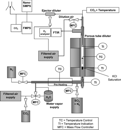
The experimental part of the study was carried out in the laboratory using a tubular laminar flow reactor to produce a synthetic test aerosol, which consisted of the two principal components present in aerosols from large biomass-fired furnaces; KCl and K2SO4 (). The flow reactor section was a vertical electrically heated tube furnace with the same construction as described by Sippula et al. (Citation2008). Inside the reactor furnace was a silicon carbide (SiC) tube with an inner diameter of 28 mm. The generation system for synthetic species was installed below the reactor and the sampling was carried out from the top of the reactor as in the earlier studies (Sippula et al. Citation2008). The furnace temperatures varied between 700 and 950°C in the measurements.
KCl vapor was supplied into the reactor using a saturator tube (20-mm inner diameter) inserted into the reactor. The top of the saturator tube includes a bed of alumina pellets with 4 cm in height (). The pellets were impregnated with KCl by soaking them in KCl–water solution, after which the pellets were dried in an oven. Two thermocouples (K-type) were installed inside the saturator to monitor and regulate the temperature inside the pellet bed. The first thermocouple was placed radially in the middle of the pellet bed, while the second thermocouple was placed near the inner wall of the saturator. A preheated nitrogen flow (1 slpm) was conducted to flow through the bed, to carry the evaporated KCl into the reactor. In addition, a secondary flow (5 slpm) was transferred into the reactor, flowing around the saturator tube. This flow consisted of filtered dry air with varying concentrations of SO2 (0–458 ppm), CO2 (5–6%), and H2O vapor (5000–70,000 ppm). The flows were controlled by mass flow controllers and critical orifices. CO2 was added into the reactor as a marker gas, to determine the DR of the diluting sampling probe. SO2 and H2O were added into the reactor to reproduce gas-phase sulfation of KCl vapor inside the reactor, which led to the formation of K2SO4 particles. The global reaction scheme for this is given in EquationEquation (1). The particle formation mechanism is the same as that occurring in biomass-fired furnaces (Christensen et al. Citation1998) but it has also been demonstrated earlier in the laboratory by using synthetic species (Jensen et al. Citation2000). The operation of the H2O supply system has been described by Hämeri et al. (Citation2000) and Joutsensaari et al. ( Citation2001). The measurement conditions are listed in
TABLE 1 Reactor and sampling conditions, particle concentrations, and particle size modes
For the characterization of the experimental setup, a CFD calculation was performed in Ansys Fluent 12.1 (see supplemental information), showing that the residence time was sufficient to allow mixing of SO2, and the saturator flow and the gas temperature remained high enough throughout the reactor tube to avoid saturation of KCl vapor, despite the cooling effect of the SO2 containing flow.
The amount of K2SO4 formed was monitored by measuring SO2 and HCl concentrations using an FTIR gas analyzer (Gasmet). The diluted samples were analyzed for particle size distributions using Nano-SMPS (Scanning mobility particle sizer, TSI) consisting of TSI CPC3025 and TSI DMA 3085. The Nano-SMPS was set to measure particle sizes between 3 nm and 64 nm. In addition, an FMPS (Fast mobility particle sizer, TSI) was used to measure particles in the size range 6–523 nm. The diffusion losses of particles in the sampling line after dilution were estimated by the equations described by Brockmann (Citation2001) for laminar tube flow giving particle penetrations for the earlier mentioned size ranges of 55–100% for Nano-SMPS and 81–100% for FMPS. Furthermore, the diffusion losses inside the SMPS were assessed by using the AIM software (version 8.0.0.0, TSI).
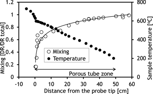
In order to obtain information on the conditions inside the diluter, axial profiles of sample temperature were measured at the basic location of the probe and with two different DRs, 20 and 85. In addition, axial profile of the mixing with the dilution air was measured with a DR of 20 by sampling a small flow (≈0.5 slpm) at different axial locations into a CO2 analyzer. This was done by moving a thin (outside Ø of 3 mm) steel probe at the centerline of the diluter. At the same time, the overall DR was determined based on CO2 measurements of the reactor and diluter exhaust flows (EquationEquation (2)). The volume flow into the thin steel probe was approximately the same as the incoming sample flow at the probe tip, while inside the diluting probe the sample flow was only a small share of the total flow and thus mainly represents a thin stream in the centerline of the diluter. The temperatures were measured similarly by moving a K-type thermocouple along the centerline of the diluter.
MODELING
The experimental results on particle size distributions were interpreted using the one-dimensional nodal point aerosol dynamics model described by Jokiniemi et al. (Citation1994). The same code has also earlier been used for the calculation of the aerosol dynamics in a porous tube diluter (Backman et al. Citation2002). The model solves the general aerosol dynamics equation (GDE) for number and mass in one-dimensional form. The GDE for the discretized number concentration is
The diluter was divided into 27 nodes based on mixing and temperature measurements, which were given as input data for the model. The amount of K2SO4, determined by the gas-phase HCl measurements, was specified as inert particles with particle size and size deviation equal to the larger mode measured by Nano-SMPS in case 13 (). The classical nucleation rate was multiplied by different factors and of these a value of 15,000 was found to provide qualitatively a good agreement between model and experiments. The multiplication of the classical nucleation rate is generally needed in one-dimensional modeling to get realistic nucleation rates (Backman et al. Citation2002; Mitrakos et al. Citation2008).
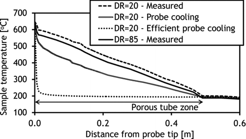
In addition to the measured temperature profile, two fictive temperature profiles were used to gain information on the effects of probe cooling, which can be achieved by a separate cooling fluid circulation around the probe. At the same time, the sensitivity of the simulation model on the temperature profile was checked. Two different cases were considered. The “probe cooling” was calculated by assuming linear axial temperature profile of the dilution gas and immediate mixing of the gases. This profile is intended to mimic efficient air cooling or water cooling. The “efficient cooling” leads to rapid temperature decrease and it was calculated by assuming a constant dilution air temperature along the whole diluter and immediate mixing. This kind of temperature profile could be achieved for example by very efficient water cooling.
RESULTS AND DISCUSSION
Test Aerosol Generation
The used KCl supply concentrations in the experiments were between 169 and 203 mg/m3 in standard conditions (20°C, 101 325 Pa) estimated based on the KCl saturation curve and saturator temperature measurements. The supply of SO2 into the reactor resulted in KCl sulfation efficiencies (i.e., KCl conversion according to EquationEquation (1)) between 32% and 78% (results in Supplemental information, available online).
With saturators, there is always the question of whether the evaporation is diffusion-limited and therefore lower than expected based on the saturation vapor curve. In an attempt to examine the real vaporization of the KCl, in addition to measurements with different SO2 concentrations, tests with a high moisture content (Case 16, 6% H2O) were also carried out to enhance the sulfation reaction. The HCl release under these high sulfation conditions was 86% of the theoretically assumed chlorine supply, indicating that the saturation vapor curve did not significantly underestimate the KCl supply. Moreover, uncertainties in the saturation temperature measurements, and losses in the reactor and sampling of the HCl may have accounted for the observed difference.
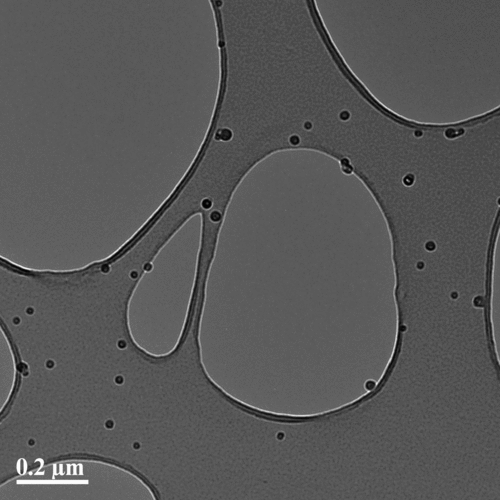
In conditions similar to those in case 12 (), the generated particles were collected on holey carbon copper grids by suction sampling (Lyyränen, Backman, et al. Citation2009) and checked with a transmission electron microscope combined with energy dispersive spectroscopy (TEM-EDS, Philips CM-200 FEG/STEM). The observed particles were mainly single primary particles () composed of potassium and sulfur. The absence of chlorine is probably due to the evaporation of KCl from the sample in the TEM.
Sampling Conditions
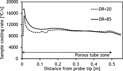
Mixing of the sample with the dilution air in the diluter was found to be fast, occurring mainly close to the probe tip (). This was influenced by the geometry of the diluter where the middle tube directs the dilution gas flow to the probe tip. However, the measurements indicated that the whole length of the diluter was needed for total mixing of the sample with dilution gas, which was expected since the aim of the porous wall was to provide a sheath dilution gas flow all along the tube. The temperature profile in the diluter was rather linear and indicated that the dilution air was efficiently preheated in the outer shell of the probe before the dilution process. Increase in DR from 20 to 85 decreased sample temperatures only slightly (), since the total flow rate from the diluter was kept at constant 10 slpm. However, an increase of DR elevated the cooling rate close to the probe tip, which can be seen from the cumulative sample cooling rate plots (calculated based on the measured temperatures and mixing along the centerline of the probe) (). Based on these measurements, the overall cooling rates throughout the diluter with both DRs were from 8000 to 9000°C/s and differed significantly only close to the probe tip. However, this is likely to affect the condensation behavior of KCl vapor. It must be noted that the flow rates in the diluting probe were not adjusted to achieve a maximal cooling rate, since the aim was to create similar conditions that had been typically used in earlier studies (Sippula et al., Citation2008).
Measured Particle Size Distributions
When only KCl vapor was introduced as the test aerosol into the reactor, the particle number size distributions were unimodal and the formed particles were very small (, case 1 and Supplemental information, available online), mainly below 20 nm. The particle size distributions were sensitive to the used DR, such that an increase of primary DR increased the number concentration and decreased the particle size. The DR-corrected particle number concentrations were very high, indicating that the particles were mainly being formed during the dilution of the sample. However, in the tests with high KCl concentrations (≈60 ppm), an “elbow” could be detected in the size distributions toward larger particles. The sampling temperature in location B was found to be lower than originally assumed, probably due to cooling effect of the probe (∼670°C). Since the sampling temperature used was equal to the KCl saturation concentration of roughly 50 ppm, some of the KCl vapors probably nucleated and condensed before the entry of the sample into the probe, explaining the slight secondary mode. These sampling point conditions may also have caused losses of the sample onto the probe tip by vapor condensation. However, this effect could not be measured with the present setup.
FIG. 7 Particle size distributions with (a) various K2SO4/KCl ratios, (b) various primary DRs, (c) various sampling locations, and (d) comparison of simulated and measured particle size distributions. The number concentrations are dilution-corrected.
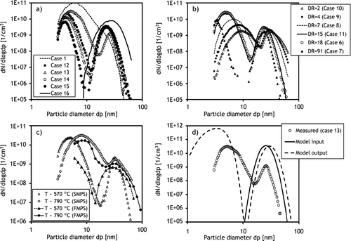
When SO2 was introduced into the reactor, the particle size distributions were clearly bimodal. The gas-phase sulfation reaction generates K2SO4 vapor into the reactor, which rapidly supersaturates in the prevailing temperatures, and thus, K2SO4 particles are being formed by homogeneous nucleation (Jensen et al. Citation2000). In addition, due to sulfation, the amount of KCl vapor decreased in the reactor and therefore no condensation of KCl should have occurred before entry to the diluting probe. Increase in the sulfate concentration clearly increased the number concentration in the larger size mode, while the smaller size mode decreased in both the concentration and the particle size (). Thus, the smaller size mode is evidently formed by homogeneous nucleation of KCl vapor in the sampling probe. The “high sulfation” case (case 16, ) removed the small size mode entirely () probably due to the very low amount of KCl vapor in the sample.
TABLE 2 Calculated cases of aerosol dynamics in the diluting probe, the mass fractions of KCl in the nucleation mode (PM0.01), and particle size distribution modes after the sampling line
In the experiments, the secondary dilution was kept constant, while the primary DR varied. Increase in the primary DR, without increase in the total sample flow rate from the sampling probe, was found to decrease the size of both modes. In addition, increase of DR clearly raised the number concentration in the KCl-nucleation mode, evidencing that a large primary DR favored nucleation of vapors instead of condensation onto existing particles (). Although the total flow rate in the probe did not change, the large primary DR simultaneously increased the sample cooling and mixing rates close to the probe tip, which may favor nucleation. One exception is the highest DR (primary DR = 91) where the number concentration of the KCl-mode was relatively low when compared to the other cases. However, this was probably related to losses in the sampling lines and instruments, despite diffusion loss corrections made, due to the very small size of the particles. Furthermore, the whole mode was clearly not visible with the minimum size detection limit of 3 nm. A similar relation between DR and the size of KCl-nucleation mode was also found in the experiments of Strand et al. (Citation2004) with the exception that with very high DR (100) no nucleation mode was observed due to sample losses or limited size detection (Dp > 10 nm) of the aerosol analyzers. Although the studies utilized different probe constructions and different conditions (temperature profiles, seed particle sizes, etc.), the basic phenomena on the behavior of the KCl vapor seems to be similar.
The increase in the sampling temperature was found to increase the total particle number concentration, while no clear trends between particle size modes and temperature were observed. The KCl-mode included more mass at higher temperatures and the separation of the two modes was not as clear as at lower temperatures (). Since the sampling temperature was changed by moving the position of the sampling probe tip, this change affected several parameters (the residence time in the reactor, inlet temperature, and temperature of the dilution air flowing through the porous wall) resulting in complex changes in the aerosol dynamics. Although the measurement of such small nanoparticles may result in significant losses inside the instrumentation, the number size distributions of Nano-SMPS and FMPS analyzers were in good agreement ().
Model Results
The calculated cases included two measured sampling conditions with DR = 20 and DR = 85 and two fictive sampling temperature profiles (“probe cooling” and “efficient cooling”; ), which are meant to simulate the effect of additional probe cooling. The concentrations of the species were taken from measured case 13 () but to check on the sensitivity, the model runs were carried out with 0%, 10%, and 100% of the measured K2SO4 particles as input ().
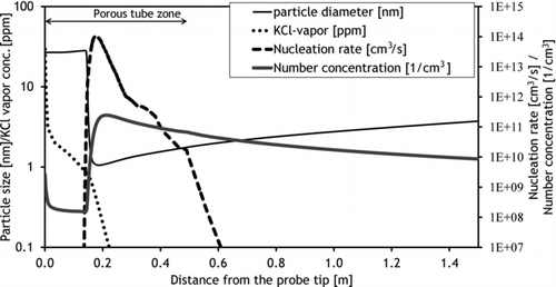
shows the calculated particle number concentration, geometric mean particle size, nucleation rate, and KCl vapor concentration in the probe for simulation 5 (), which corresponds to the measured case 13. The simulation predicted that the number concentration first declines at the probe inlet due to coagulation of seed particles and dilution. However, at around 14 cm from the probe tip, the number concentration was rapidly elevated, due to the nucleation of KCl vapor, and reached its maximum when the nucleation rate was at its maximum. This resulted in the appearance of very small KCl particles in the sample at the outlet of the sampling system, similarly to that found in the experimental results.
The KCl vapor was found to nucleate homogeneously in all of the calculated cases (). In each of the simulations with seed particles present, a fraction of the KCl vapor was found to condense on the seed particles just at the probe tip before dilution due to a temperature drop, which saturates the vapor. In contrast, after dilution, the vapors condensed mainly in the nucleation mode. With the measured temperature profiles, the residual part of the vapor condensation took place after a significant amount of sample dilution had occurred. These results indicate that this residual vapor fraction tended to nucleate rather than condense on existing particles due to the high saturation ratio. The highest nucleation rates were found between 14 and 17 cm from the probe tip when using the measured temperature profiles. The saturation ratios were in those locations at values between 20 and 30, which explain the tendency for homogeneous nucleation, although a very high surface area is provided by the seed particles. After this point, the saturation ratio of the KCl vapor continued to increase but the nucleation rate declined, since most of the vapors had already been depleted.
FIG. 9 The mass size distributions of condensed KCl inside the diluter. (Color figure available online.)
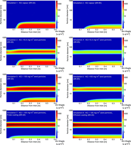
An increase in the seed particle concentration clearly increased the condensation of KCl on seeds at the cost of nucleation, as was expected. Elevating the DR from 20 to 85 increased the presence of KCl in the nucleation mode at the cost of condensation on seeds and decreased the nucleation mode particle size, similar to the experimental results with high DR (). This was found to be due to the higher dilution in the region close to the probe tip, which decreased the KCl vapor concentration and delayed its condensation to diluted conditions where the vapors mostly condensed on the nucleation mode.
Simulations with fictive temperature profiles were carried out to mimic cooled dilution gas. In these cases, the cooling of the sample was considerably faster, which was found to move to the location where nucleation began toward the probe tip () but decreased the KCl mass fraction in the nucleation mode. This appeared to be related to the seed particle concentrations, which were clearly higher at the probe inlet than 15 cm after the inlet where most of the mixing with the dilution air had already occurred (). In “probe cooling,” only a very minor fraction (<1 m%) of the KCl was estimated to be in the nucleation mode since nearly all of the vapors condensed on the seed particles at the inlet. In the “efficient cooling” case, the high cooling rate of the sample (around 105°C/s at the inlet) reproduced the nucleation of KCl vapor close to the inlet, and as a result, 4% of KCl was found in the nucleation mode. These results indicate that although the temperature profile has an important effect on KCl vapor behavior in the probe, the basic phenomenon on the alkali chloride vapor nucleation in the probe may occur under highly different conditions.
The simulated and measured particle size distributions agree on a qualitative level (), which can be expected since simulations were carried out with a relatively simple one-dimensional model that cannot take into account real temperature, concentration, and velocity distributions in the probe. Furthermore, the experimental results include uncertainties due to the very small size of the particles, which require estimations of diffusion losses in the sampling lines and inside the instruments as well as considerations of particle charging efficiencies in the instrument. In addition, the measured temperature profiles include uncertainties due to heat radiation between thermocouple and surrounding walls. Despite these uncertainties, the simulations match qualitatively the experimental results and were able to reproduce similar particle size distributions both with and without seed particles. In addition, the effect of primary DR on particle size distributions was the same in experiments () and in simulations (). Thus, the use of the simple aerosol dynamic model can be useful in the interpretation of the experimental findings and to predict the effects of sampling and process conditions on aerosol properties.
CONCLUSIONS
Two-component model aerosols consisting of KCl vapor and ultrafine K2SO4 particles were generated in the laboratory to study the effects of sampling conditions and sample properties on sample transformation in a high-temperature porous tube sampling probe. The particle size distributions were sensitive to the sampling conditions, as expected. In most cases, the KCl was mainly in the gas phase during the sampling, and very small KCl particles were formed inside the porous tube diluter by homogeneous nucleation. In the cases where K2SO4 particles were produced within the reactor, part of the KCl vapor condensed on the existing particles, while the remainder formed a nucleation mode due to the relatively high cooling rates in the probe, resulting in a bimodal particle size distribution. Similar findings on the behavior of KCl vapor in a quench probe have been observed in some other studies, e.g., Strand et al. (Citation2004) and Jimenez and Ballester (Citation2011). The condensation behavior of KCl in the probe with simultaneous dilution and cooling was found to be complex and to depend on several parameters. First, the surface area of the existing particles to a large extent defined the distribution between the vapor condensed on seed particles and in the nucleation mode. Second, the mixing and temperature profiles defined the saturation of the vapors in different parts of the sampling line. In the studied probe, the mixing was found to be relatively fast at the probe tip, and the simulations indicated that this delayed the condensation of KCl to diluted conditions, which was found to favor nucleation instead of condensation onto the seed particles. In contrast, the aerosol dynamics calculations simulating the use of cooled dilution gas in the probe indicated that there would be a lower fraction of KCl in the nucleation mode and enhanced condensation on seed particles close to the probe tip.
In high-temperature particle formation studies, the separation of gas phase and particulate phase fly ash compounds in the sampling system is important to avoid significant errors and false interpretation of the results. The results of this study indicate that a separation of condensable gases and already existing fine particles to different particle size classes is possible, but the sampling technology needs to be developed further to optimize the conditions. However, also in the current sampling system, different sampling parameters can be used either to enhance the appearance of the nucleation mode, which acts as an indicator for the existence of gas-phase fly ash forming compounds, or to promote condensation of vapors on existing particles. The latter is important for studies aiming to measure the total particulate forming material, since the nucleation mode particles easily become lost on the walls by diffusion. The temperature of the dilution gas and the DR were essential parameters controlling the condensation–nucleation of fly ash forming vapors inside the sampling probe. Furthermore, the cooling rate of the sample can be considerably increased or decreased by orders of magnitude by changing the flow rates in the probe. The experiments and computer simulations were qualitatively in agreement, demonstrating the applicability of a relatively simple aerosol model for helping in the interpretation of the results and in pre-evaluating different sampling probe constructions. In addition, the use of the present probe combined with the simple aerosol dynamics model could provide valuable information when applied for monitoring the real world furnaces.
Based on this study, two different approaches were identified for developing quench sampling at high temperatures, in order to separate the condensable vapors into a distinct nucleation mode. First, fast cooling close to the probe tip leads to a high saturation ratio. If the cooling is fast enough and the sample reaches sufficiently low temperatures, nucleation of KCl (and other possible vapors with appropriate vapor pressures) occurs despite the high surface area available for condensation at the probe inlet. In the second approach, the sample could be first diluted with hot dilution gas, which decreases the seed particle concentration. After the first dilution stage, the sample is diluted rapidly with a cool gas, which reproduces a high sample cooling rate.
uast_a_700741_sup_26740361.zip
Download Zip (344.7 KB)Acknowledgments
Financial support from the Finnish Funding Agency for Technology and Innovation, Metso Power, Lassila-Tikanoja, Kemira, and Helsinki Water and the strategic funding of the University of Eastern Finland (Sustainable Bioenergy, Climate Change, and Health) is acknowledged. The authors thank Dr. Unto Tapper from the VTT Technical Research Centre of Finland for TEM images and Mr. Pentti Willman from the University of Eastern Finland for technical support.
[Supplementary materials are available for this article. Go to the publisher's online edition of Aerosol Science and Technology to view the free supplementary files.]
REFERENCES
- Backman , U. , Jokiniemi , J. K. , Auvinen , A. and Lehtinen , K. E. J. 2002 . The Effect of Boundary Conditions on Gas-Phase Synthesised Silver Nanoparticles . J. Nanopart. Res. , 4 : 325 – 335 .
- Baxter , L. L. , Miles , T. R. , Miles , T. R. , Jenkins , B. M. , Milne , T. Dayton , D. 1998 . The Behavior of Inorganic Material in Biomass-Fired Power Boilers: Field and Laboratory Experiences . Fuel Process. Technol. , 54 : 47 – 78 .
- Brockmann , J. E. 2001 . “ Sampling and Transport of Aerosols ” . In Aerosol Measurements: Principles, Techniques and Applications , Edited by: Baron , P. A. and Willeke , K. 143 – 195 . New York : John Wiley & Sons .
- Christensen , K. A. , Stenholm , M. and Livbjerg , H. 1998 . The Formation of Submicron Aerosol Particles, HCl and SO2 in Straw-Fired Boilers . J. Aerosol Sci. , 29 : 421 – 444 .
- Deuerling , C. F. , Maguhn , J. , Nordsieck , H. O. , Warnecke , R. and Zimmermann , R. 2010 . Measurement System for Characterization of Gas and Particle Phase of High Temperature Combustion . Aerosol Sci. Technol. , 44 : 1 – 9 .
- Hämeri , K. , Väkevä , M. , Hansson , H.-C. and Laaksonen , A. 2000 . Hygroscopic Growth of Ultrafine Ammonium Sulphate Aerosol Measured Using an Ultrafine Tandem Differential Mobility Analyzer . J. Geophys. Res. , 105 ( 22 ) : 231 – 242 .
- Jensen , J. R. , Nielsen , L. B. , Schultz-Møler , C. , Wedel , S. and Livbjerg , H. 2000 . The Nucleation of Aerosols in Flue Gases with a High Content of Alkali-A Laboratory Study . Aerosol Sci. Technol. , 33 : 490 – 509 .
- Jiménez , S. and Ballester , J. 2005 . A Comparative Study of Different Methods for the Sampling of High Temperature Combustion Aerosols . Aerosol Sci. Technol. , 39 : 811 – 821 .
- Jiménez , S. and Ballester , J. 2011 . Use of a Berner Low-Pressure Impactor at Low Inlet Pressures. Application to the study of Aerosols and Vapors at High Temperature . Aerosol Sci. Technol. , 45 : 851 – 861 .
- Johansson , L. S. , Leckner , B. , Tullin , C. , Åmand , L. -E. and Davidsson , K. 2008 . Properties of Particles in the Fly Ash of a Biofuel-Fired Circulating Fluidized Bed (CFB) Boiler . Energy Fuels , 22 ( 5 ) : 3005 – 3015 .
- Jokiniemi , J. K. , Lazaridis , M. , Lehtinen , K. E. J. and Kauppinen , E. I. 1994 . Numerical Simulation of Vapor-Aerosol Dynamics in Combustion Processes . J. Aerosol Sci. , 25 : 429 – 446 .
- Joutsensaari , J. , Vaattovaara , P. , Vesterinen , M. , Hämeri , K. and Laaksonen , A. 2001 . A Novel Tandem Differential Mobility Analyzer with Organic Vapor Treatment of Aerosol Particles . Atmos. Chem. Phys. , 1 : 51 – 60 .
- Kittelson , D. B. 1998 . Engines and Nanoparticles: A Review . J. Aerosol Sci. , 29 : 575 – 588 .
- Lipsky , E. M. , Pekney , N. J. , Walbert , G. F. , O’Dowd , W. J. , Freeman , M. C. and Robinson , A. 2004 . Effects of Dilution Sampling on Fine Particle Emissions from Pulverized Coal Combustion . Aerosol Sci. Technol. , 38 : 574 – 587 .
- Lipsky , E. M. , Stanier , C. O. , Pandis , S. N. and Robinson , A. L. 2002 . Effects of Sampling Conditions on the Size Distribution of Fine Particulate Matter Emitted from a Pilot-Scale Pulverized-Coal Combustor . Energy Fuels , 16 : 302 – 310 .
- Lyyränen , J. , Backman , U. , Tapper , U. , Auvinen , A. and Jokiniemi , J. 2009 . A Size Selective Nanoparticle Collection Device Based on Diffusion and Thermophoresis. Nanosafe 2008: International Conference on Safe Production and Use of Nanomaterials . Journal of Physics: Conference Series 170 ,
- Lyyränen , J. , Jokiniemi , J. , Kauppinen , E. I. , Backman , U. and Vesala , H. 2004 . Comparison of Different Dilution Methods for Measuring Diesel Particle Emissions . Aerosol Sci. Technol. , 38 : 12 – 23 .
- Michelsen , H. P. , Frandsen , F. , Dam-Johansen , K. and Larsen , O. H. 1998 . Deposition and High Temperature Corrosion in a 10 MW Straw Fired Boiler . Fuel Process. Technol. , 54 : 95 – 108 .
- Mikkanen , P. , Kauppinen , E. I. , Pyykönen , J. , Jokiniemi , J. K. , Aurela , M. Vakkilainen , E. K. 1999 . Alkali Salt Ash Formation in Four Finnish Industrial Recovery Boilers . Energy Fuels , 13 : 778 – 795 .
- Mitrakos , D. , Jokiniemi , J. , Backman , U. and Housiadas , C. 2008 . Aerosol Flow in a Tube Furnace Reactor of Gas-Phase Synthesised Silver Nanoparticles . J Nanopart. Res. , 10 : 153 – 161 .
- Obernberger , I. , Fluch , J. and Brunner , T. 2009 . Comparative Characterization of High Temperature Aerosols in Waste Wood Fired Fixed-Bed and Fluidized-Bed Combustion Systems . 17th European Biomass Conference and Exhibition, 29 June–3 July 2009, Hamburg, Germany
- Pyykönen , J. , Miettinen , M. , Sippula , O. , Leskinen , A. , Raunemaa , T. and Jokiniemi , J. 2007 . Nucleation in a Perforated Tube Diluter . J. Aerosol Sci. , 38 : 172 – 191 .
- Sippula , O. , Hokkinen , J. , Puustinen , H. , Yli-Pirilä , P. and Jokiniemi , J. 2009a . Particle Emissions from Small Wood-Fired District Heating Units . Energy Fuels , 23 : 2974 – 2982 .
- Sippula , O. , Hokkinen , J. , Puustinen , H. , Yli-Pirilä , P. and Jokiniemi , J. 2009b . Comparison of Particle Emissions from Small Heavy Fuel Oil and Wood Fired Boilers . Atmos. Environ. , 43 : 4855 – 4864 .
- Sippula , O. , Hytönen , K. , Tissari , J. , Raunemaa , T. and Jokiniemi , J. 2007 . Effect of Wood Fuel on the Emissions from a Top-Feed Pellet Stove . Energy Fuels , 21 : 1151 – 1160 .
- Sippula , O. , Lind , T. and Jokiniemi , J. 2008 . Effects of Chlorine and Sulfur on Particle Formation in Wood Combustion Performed in a Laboratory Scale Reactor . Fuel , 87 : 2425 – 2436 .
- Strand , M. , Bohgard , M. , Swietlicki , E. , Gharibi , A. and Sanati , M. 2004 . Laboratory and Field Tests of a Sampling Method for Characterization of Combustion Aerosols at High Temperatures . Aerosol Sci. Technol. , 38 : 757 – 765 .
- Tissari , J. , Sippula , O. , Kouki , J. , Vuorio , K. and Jokiniemi , J. 2008 . Fine Particle and Gas Emissions from the Combustion of Agricultural Fuels Fired in a 20 kW Burner . Energy Fuels , 22 : 2033 – 2042 .
- Valmari , T. , Kauppinen , E. I. , Kurkela , J. , Jokiniemi , J. K. , Sfiris , G. and Revitzer , H. 1998 . Fly Ash Formation and Deposition During Fluidized Bed Combustion of Willow . J. Aerosol Sci. , 29 : 445 – 459 .
- Valmari , T. , Lind , T. M. and Kauppinen , E. I. 1999a . Field Study on Ash Behavior during Circulating Fluidized-Bed Combustion of Biomass 1. Ash Formation . Energy Fuels , 13 : 379 – 389 .
- Valmari , T. , Lind , T. M. and Kauppinen , E. I. 1999b . Field Study on Ash Behavior during Circulating Fluidized-Bed Combustion of Biomass 2. Ash Deposition and Alkali Vapor Condensation . Energy Fuels , 13 : 390 – 395 .
- Van Loo , S and Koppejan , J. 2008 . The Handbook of Biomass Combustion and Co-Firing , London : Earthscan .
