Abstract
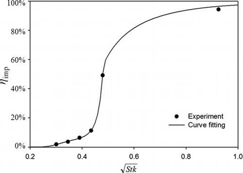
We designed a thermal precipitator in a cylindrical configuration with a size-selective inlet, and investigated its performance in experiments using differential mobility analyzer (DMA)-classified particles of sodium chloride (NaCl) and polystyrene latex (PSL). Our investigation was performed in two parts: (1) using the size-selective inlet to determine the best inlet-to-wall distance for optimal impaction of 1 μm particles; (2) using a simple inlet tube to measure particle collection via thermophoresis over a size range from 40 nm to 1000 nm. The results showed that the inlet had a particle cut-off curve, with a 50% particle cut-off Stokes number of 0.238, resulting in removing particles with sizes larger than 1 μm at an aerosol flow rate of 1.5 lpm. The thermophoretic particle collection efficiency in the prototype was measured without the size-selective inlet installed. The size dependence of the collection efficiency was negligible for particles with diameters ≤300 nm and became noticeable for those with diameters >300 nm. An analytical model was further developed to estimate the particle collection efficiency due to thermophoresis of the prototype under various aerosol flow rates and temperature gradients. For particles with diameters less than 400 nm, reasonable agreement was obtained between the measured data and the collection efficiency calculated from the developed analytical model. It was further concluded that the derived formula for the calculation of thermophoretic particle collection efficiency could serve as the backbone for future design of thermal precipitators in any configuration, when combined with the proper formula for the dimensionless thermophoretic particle velocity.
Copyright 2012 American Association for Aerosol Research
1. INTRODUCTION
Epidemiological studies have revealed that increased ambient air particulate matter (PM) concentration is associated with an increase in morbidity and mortality (Dockery et al. Citation1993; Krewski et al. Citation2000; Pope and Dockery Citation2006). Recent cell experimental studies (Li et al. Citation2003) and epidemiological studies (Bräuner et al. Citation2009; Patel and Miller Citation2009) further show that fine/ultrafine particles are strongly related to human pulmonary and cardiovascular diseases, cancer, and mortality. Such particles can translocate through the epithelium of terminal bronchioles and alveoli (Chalupa et al. Citation2004; Geiser et al. Citation2005). Sampling fine and ultrafine particles is a necessary step to study their toxicity via in vitro experiments. Filtration and impaction techniques are commonly used for sampling ambient particles in traditional in vitro cell experiments. Ultrasonication is often utilized to retrieve collected particles from either filter media or the impactor substrate (Osornio-Vargas et al. Citation2003; Hetland et al. Citation2004). The violent sonication increases the chance of damage or alteration of the physical and chemical properties of collected particles (e.g., their size distribution, contents of water soluble organic and metal compounds, physical structure, and surface morphology). Consequently, such changes in the properties of particles may mislead the results in in vitro ambient particle toxicity studies (Kim et al. Citation2001). For the toxicity study via in vitro experiments and for the characterization of their physical and chemical composition, structure, and surface morphology, we must first collect enough fine/ultrafine particles with relatively unchanged physical chemical characteristics compared with particles suspending in the ambient air condition.
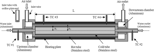
FIG. 1 The schematic cross-section of the cylindrical precipitator design (not to scale). The inlet tubes for air inlet and outlet are detachable. TC = thermocouple; R 1 = 34.93 mm; R 2 = 35.61 mm.
Thermophoresis is the physical phenomenon of particles moving from the high to low temperature zones in a temperature-varied field (Talbot et al. Citation1980; Hinds 1999). The thermophoretic force acting on particles, is in general much weaker than that attributed to either particle impaction or sonication, leading to well-maintained characteristics of sampled particles (Dobbins and Megaridis Citation1987). Various types of thermal precipitators based on the thermophoretic effect have been designed to collect concerned particles (Kethley et al. Citation1952; Orr and Martin Citation1953; Montassier et al. Citation1991; Messerer et al. Citation2003; Lorenzo et al. Citation2007; Wang et al. 2012). However, thermophoretic particle samplers are not widely used to collect ambient particles for environmental studies, because thermophoretic velocity formula remains unsettled, particularly for large particles (Bakanov Citation1991; Santachiara et al. Citation2002).
The theoretical treatment of particle thermophoresis is categorized by the particle Knudsen number (Kn) defined as the ratio of the mean free path of carrier gas to particle radius. For particles in the free-molecule regime (Kn ≫ 1), the work in Schmitt (Citation1959), Waldmann (Citation1959), and Waldmann and Schmitt (Citation1966) gave reasonable description of particle thermophoretic velocity. For particles in the transition (Kn ≈ 1) and continuum (Kn ≪ 1) regimes, Talbot et al. (Citation1980) proposed a more accurate formula to estimate the particle thermophortic velocity than those published in other early literature (Epstein Citation1929; Brock Citation1962; Derjaguin et al. Citation1976). The formula proposed by Talbot et al. (Citation1980) has been often used in thermophoresis-related research and development (Tsai and Lu Citation1995; Messerer et al. Citation2003; Azong-Wara et al. 2009). However, recent studies (Santachiara et al. Citation2002) found that the thermophoretic velocities of sodium chloride (NaCl) particles predicted by Talbot's formula are over-estimated for cases with the sizes larger than 0.5 μm. The collection efficiency of polystyrene latex (PSL) particles is also over-estimated in all the tested size range (i.e., 0.2–1.66 μm).
Cylindrical precipitators may have been first developed by Bredl and Grieve (Citation1950) to collect all the solid matter from a representative sample of flue gases. The performance of thermal precipitators in the cylindrical configuration has been investigated in the literature (Stratmann and Fissan Citation1989; Montassier, et al. Citation1990; Stratmann et al. Citation1994; Romay, et al. Citation1998; Sagot, et al. Citation2009). However, the relation between thermophoretic particle collection efficiency and precipitator configuration, the inlet flow rate, particle deposition area, and temperature gradients have not been developed. Thus, the design of cylindrical precipitators remains empirical.
To apply thermal precipitators for collecting fine and ultrafine particles from ambient air and to investigate the thermophoretic velocity of particles with diameters ≤1 μm, we designed a cylindrical thermal precipitator with a size-selective inlet. The size-selective inlet enabled the removal of particles larger than certain super-micrometers in diameter, which may not be of concern in particle toxicity studies. For example, toxicity studies of fine and ultrafine particles may wish to remove particles with diameter larger than 1 μm. In addition to calibrating the optimal distance between the size-selective inlet and the impaction plate surface, this study also evaluated the particle collection efficiency of the thermal precipitator (i.e., particle collection efficiency) under various operational conditions (i.e., aerosol flow rate and temperature gradient), especially for particles in large sizes (i.e., from 600 nm to 1.0 μm). The cylindrical thermal precipitator studied is described in detail in the following sections.
2. DESCRIPTION OF CYLINDRICAL THERMAL PRECIPITATOR
A schematic diagram of our studied cylindrical thermal precipitator is shown in . It consists of a detachable size-selective inlet, two aerosol chambers (upstream and downstream), and two co-axially aligned stainless steel cylinders. The inner diameter (ID) of the outer cylinder is 34.93 mm (R
1), and the outer diameter (OD) of the inner cylinder is 35.61 mm (R
2), resulting an annular space of 0.68 mm. The thermal precipitation length (i.e., the cold tube length, L) in the precipitator is approximately at 20 cm. The aerosol flow entering the annular precipitation zone is assumed to be in fully developed velocity profile. The above assumption is supported by the low Reynolds number (Re) of the flow in the annular spacing of the precipitator: at an airflow rate of 2.0 L/min (lpm), which is the maximal flow rate used in our evaluation, the flow Reynolds number was 39.49 at the ambient temperature. Here, ![]() , where ρ
g is air density, and D
h is hydrodynamic diameter, which is equal to 2(R
2 −R1). The hydrodynamic entrance length of this annular flow was estimated at 0.11 cm (i.e., 0.04 × Re × D
h; Schlichting Citation1979), which is negligible as compared to the precipitation length. The airflow in the annular spacing can thus be considered to be laminar and in a fully developed velocity profile. Two identical annular chambers at each end of the precipitator (upstream and downstream) ensure a uniform spatial distribution of aerosol concentration before and after the precipitation region, respectively. Aerosol flow first enters the upstream chamber via the inlet tube, located on the sidewall of the chamber, prior to the narrow annular precipitation spacing.
, where ρ
g is air density, and D
h is hydrodynamic diameter, which is equal to 2(R
2 −R1). The hydrodynamic entrance length of this annular flow was estimated at 0.11 cm (i.e., 0.04 × Re × D
h; Schlichting Citation1979), which is negligible as compared to the precipitation length. The airflow in the annular spacing can thus be considered to be laminar and in a fully developed velocity profile. Two identical annular chambers at each end of the precipitator (upstream and downstream) ensure a uniform spatial distribution of aerosol concentration before and after the precipitation region, respectively. Aerosol flow first enters the upstream chamber via the inlet tube, located on the sidewall of the chamber, prior to the narrow annular precipitation spacing.
An inlet tube with an orifice plate as its exit end is used for the size-selective inlet of the precipitator in real applications (i.e., replacing the aerosol inlet tube shown in ). A 1.0 mm diameter orifice was used in the orifice plate. The inlet tube was positioned to face the outer wall of the fixture for the inner cylinder. The distance between the inlet tube exit and the fixture wall is adjustable via the threads made on the inlet tube. Leaving the particle precipitation region, aerosol flow is merged in the downstream chamber prior to exiting the precipitator.
Cold water flowed through the inner cylinder (i.e., cold tube) to keep the outer wall of the inner cylinder at desired low temperature. The cold water was circulated via a temperature-controlled chiller (16 1pm, Isotemp 3016D recirculator, Fisher Scientific, MA, USA). The temperature of the cold tube was assumed to be the same as that of the circulated water. The temperatures were monitored by two thermocouples separately inserted into the inlet and outlet tubes (T1 and T2). The inner wall of the outer cylinder (i.e., hot tube) was kept at a desired elevated temperature by a heating blanket (Model No. SRFG-508, OMEGA Engineering Inc., CT, USA) and a temperature controller (Model: 89810-00, Cole-Parmer, IL, USA) with feedback from a thin thermocouple (JMQSS-032-12, OMEGA Engineering Inc.). The overall length of the heating blanket was 20.32 cm and its effective length of heating was 19.69 cm. Two other thermocouples (T3 and T4) were used to measure the temperature of the hot tube.
3. EXPERIMENTAL EVALUATION
3.1. Experimental Setup
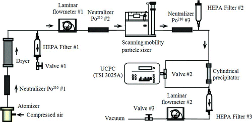
The experimental setup for the characterization of the precipitator is shown in . This setup was used to measure the particle collection efficiency of the precipitator using differential mobility analyzer (DMA)-classified NaCl (Sigma–Aldrich Co. LLC, MO, USA, k p = 6.5 W/(m·K)) particles with diameters of 40, 80, 100, 200, 300, 400, and 500 nm, and PSL particles (Duke Scientific Co., CA, USA, k p (PSL) = 0.11 W/(m·K)) with diameters of 100, 200, 400, 500, 600, 700, 800, 900, and 1000 nm. Polydisperse NaCl particles were generated by atomizing aqueous NaCl solutions at various concentrations via a custom-made Collison atomizer, and PSL particles were made by dispersing aqueous PSL suspensions in air via a UP-DRAFT nebulizer (Hudson RCI, NC, USA). The charge level of generated droplets were first minimized by a Po210 radioactive neutralizer (#1) and dried by a silica-gel diffusion dryer. Particles exiting the dryer were fed into the 2nd Po210 neutralizer to ensure the stationary charge distribution of particles was achieved prior to the electrical classification and a DMA to classify particles of the desired sizes. Two DMAs were used in this part of the evaluation. A DMA with the classification length of 44.44 cm (TSI model 3081) was used to select particles with the diameters less than 500 nm. The sheath flow rates used by the DMA for selecting particles in the diameters of 200, 300, 400, and 500 nm were 12, 10, 7.2, and 5.4 lpm, respectively. A custom-made DMA, similar to TSI DMA, with the classification length of 66 cm was utilized to classify particles with the diameters between 600 nm and 1000 nm. The sheath flow rates used in the custom-made DMA were set at 5.4 lpm. Three aerosol flow rates (1.0, 1.5, and 2.0 lpm) were chosen in our experiment. The aerosol flow rate entering the classifier was monitored by a laminar flowmeter (#1) of a single capillary type, and controlled by a needle valve (#1) in the branched exhaust line located upstream of the flowmeter. A high-efficiency particulate arresting (HEPA) cartridge filter (#1) was installed upstream of the needle valve to prevent particles from accumulating in the valve. The charges on the particles after the DMA were minimized in the third Po210 neutralizer. The particle number concentrations upstream and downstream of the precipitator were measured by an ultrafine condensation particle counter (UCPC, TSI model 3025) via a three-way valve (#2). The flow rate of the aerosol stream passing thought the precipitator was controlled by a vacuum exhaust line downstream of the precipitator. The carrier gas flow rate through the vacuum line was controlled by a second HEPA cartridge filter, second laminar flowmeter, and third needle valve. The total aerosol flow rate through the prototype was the sum of the UCPC sampling and vacuum line flow rates. The UCPC in our study was always operated at 0.3 lpm.
Note that when nebulizing suspensions of PSL particles with the sizes larger than 600 nm, the sizes of PSL particles after the DMA-classification were further verified by an aerodynamic particle sizer (APS, TSI model 3321).
3.2. Experimental Procedure
3.2.1. Measurement of Particle Collection Efficiency Due to Thermophoresis
For this part of investigation, the size-selective inlet tube was replaced with a straight tube having the same ID and OD. A DMA (TSI model 3081) was used to classify particles in the size range from 40 nm to 500 nm, and another custom-made DMA (with a classification length of 65 cm) was used for PSL particles with diameters between 100 nm and 1000 nm. The total aerosol flow rate through the precipitator was adjusted by the third needle valve in the vacuum exhaust line. The particle concentrations upstream and downstream of the precipitator were measured by a UCPC (and noted as C up and C down, respectively). The total collection efficiency (noted as η total) in the precipitator under various test conditions was simply calculated as the ratio of the particle concentrations at the downstream and upstream sampling ports (i.e., 1 − C down/C up).
The collection efficiency in the prototype due to Brownian diffusion and other factors at various temperature gradients could not be directly measured. For reference, we measured the above collection efficiency (noted as η diff) at three different aerosol flow rates with no temperature gradient applied in the precipitator. The thermophoretic particle collection efficiency of the prototype (noted as η th) was then approximately calculated as η total − η diff, where η total is the fraction of test particles collected in the precipitator with a temperature gradient applied.
3.2.2. Calibration of Size-Selective Inlet
The particle cut-off curve of the size-selective inlet was calibrated using monodisperse PSL particles with diameters of 600, 700, 800, 900, 1000, and 2000 nm. A UP-DRAFT nebulizer dispersed PSL particles in air, and an APS measured the upstream and downstream particle number concentration of the studied precipitator. The collection efficiency due to impaction (η imp) is also calculated as η total–η diff. In this part of the experiment, we first varied the distance between the orifice end plate and the fixture surface to achieve 50% collection efficiency for PSL particles of 1000 nm in diameter at aerosol flow rate of 1.5 lpm. The collection efficiencies for other PSL particle sizes were then measured at the fixed configuration.
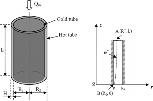
FIG. 3 Cylindrical thermal precipitator (left) and its corresponding cylindrical coordinate system (right). H: the height of between the two disks; Q in: inlet flow rate; R 1 and R 2: the radiuses of the inlet tube and disks; ψ*: the particle trajectory starting from the critical point (R*, L) and the outer edge (R 2, 0) of the cold plate.
4. ANALYTICAL MODEL FOR CYLINDRICAL THERMAL PRECIPITATOR
To analytically derive the thermophoretic particle collection efficiency of a cylindrical precipitator, we first assumed that the aerosol carrier flow was steady state, incompressible, laminar, axisymmetric, and fully developed in the narrow precipitation spacing. A schematic diagram of a simplified cylindrical precipitator with cylindrical coordinates is given in . The thermophoretic velocity of a particle was assumed to remain unchanged in the precipitation region, and can be estimated by the related formula, assuming the temperature as the average of the hot and cold temperatures. The general expression for thermophoretic velocity (U th) of a particle can be written as:
Neglecting Brownian motion and gravitational settling of particles during the transport in the precipitator, the particle trajectory in the z–r plane is governed by:
Since, particle Brownian motion and gravitational settling are not considered in this derivation, there exists a limiting particle trajectory, starting from the critical point (R*, L) at the entrance of the spacing to the outer edge (R 1, 0) of the cold tube (shown in ). Particles whose entrance positions are less than R* (i.e., r ≤ R*) were assumed to be deposited on the surface of the cold tube, while the rest were assumed to escape from the thermal precipitation. With the assumption of uniform particle concentration at the spacing entrance, the volumetric flow rate (i.e., Q collect) in which all the particles will be collected can be calculated as:
As the ratio R*/R 1 varied from 1.00 to 1.04 in our precipitator R* can be approximated as R 1. The thermophoretic particle collection efficiency was then calculated as:
5. RESULTS AND DISCUSSION
5.1. Particle Cut-off Curve of the Size-selective Inlet
The separation characteristics of the size-selective inlet of the studied precipitator were measured at no temperature gradient applied. Monodisperse PSL particles were used in this part of the experimental calibration. The distance between the orifice plate at the inlet tube exit and the surface of the centering fixture for the cold tube was set at about 0.8 mm, a distance where the collection efficiency of 1000 nm PSL particles achieved 50% at the aerosol flow rate of 1.5 lpm. The obtained ratio of the orifice-to-impaction-surface distance to the orifice diameter is 0.8, which is close to 1.0, as recommended by Marple and Willeke (Citation1976). The particle Stokes number (Stk) at the 50% cut-off efficiency was then calculated as:
FIG. 4 Experimental particle collection efficiency curve of the size-selective inlet as the function of the square root of the Stokes number when calibrated by PSL particles at 1.5 lpm. The given fitting equation for the experimental data is 
5.2. Thermophoretic Particle Collection Efficiency of the Precipitator
Note that in this part of the investigation the size-selective inlet was replaced with an identical tube without any orifice plate at the exit end.
5.2.1. Particle Collection Efficiency in the Precipitator Under no Temperature Gradient
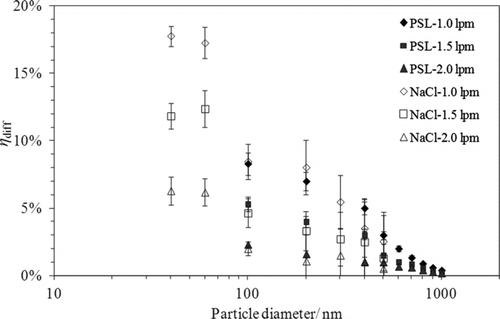
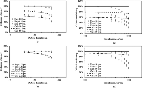
For the reference particle collection efficiency in the precipitator under no temperature gradient condition was first measured in this part of the experiment. The measured particle collection efficiency as the functions of aerosol flow rate (i.e., 1.0, 1.5, and 2.0 lpm) and particle size (ranging from 40 nm to 1000 nm) at the 20°C temperature condition is given in . As shown in the measured particle collection efficiency decreased with the increase in either particle diameter or aerosol flow rate for both NaCl and PSl particles. At the aerosol flow rate of 1.0 lpm, the particle collection efficiency was about 18% for the 40 nm NaCl particles and decreased rapidly to below 5% when the particle diameters are larger than 500 nm. PSL particles with diameters ≤500 nm had similar particle result as NaCl particles. For particles with the diameters greater than 500 nm, the particle collection efficiency decreased to less than 5% at 1.0 lpm aerosol flow rate, and was negligible at higher flow rates. The above-measured particle collection efficiency with no temperature gradient was then used in the calculation of the thermophoretic particle collection efficiency in the precipitator.
5.2.2. Particle Collection Efficiency Under Temperature Gradient
The measured and calculated thermophoretic particle collection efficiencies (based on EquationEquation (8)) of the studied precipitator for NaCl and PSL particles under two temperature gradients and at three aerosol flow rates are compared in . a and b show NaCl particles at 320 and 500°C/cm, respectively. For NaCl particles, the thermophoretic particle collection efficiency decreased about 20% when varying the particle size from 40 nm to 500 nm under 320°C/cm temperature gradient. Negligible difference was observed between experimental and calculated efficiencies based on Talbot's dimensionless thermophoretic velocity formula (EquationEquation (3)). A similar observation was also reported in a plate-to-plate type thermal precipitator in the work of Tsai and Lu (Citation1995). c and d show PSL particles under temperature gradients of 320 and 500°C/cm, respectively. For PSL particles, the thermophoretic particle collection efficiency decreased by 40% in magnitude when the size varied from 100 nm to 1000 nm. Note that a large reduction in the collection efficiency was observed for the particles with diameters greater than 400 nm as compared to that for sizes ≤400 nm. However, the calculated collection efficiency for PSL particles was nearly kept unchanged in all the tested particle sizes. Thus, greater discrepancy between the measured and calculated efficiency was observed for particles with diameters greater than 400 nm. As noted in Section 3.1, APS was further used to measure the thermophoretic particle collection efficiency for particles ≥600 nm. The experimental data obtained by both UCPC and APS were generally comparable. It is obvious that a better model for thermophoretic velocity shall be developed based on this experimental observation. Since, the objective of this work is on the development of thermophoretic sampler with the size-selective inlet we did not pursue the direction of model improvement.
FIG. 6 The comparisons between the calculated and experimental collection efficiencies for PSL and NaCl particles at three inlet airflow rates under two temperature gradients. (a) (NaCl, 320°C/cm); (b) (NaCl, 500°C/cm); (c) (PSL, 320°C/cm); (d) (PSL, 500°C/cm). Cal: calculation result obtained for the model; Exp: experimental data. The lines for the cases of Cal – 1.5 lpm and Cal – 1.0 lpm shown in (b) and (d) are overlapped.
Using the measured thermophoretic particle collection efficiency, the dimensionless thermophoretic velocity for PSL and NaCl particles can be derived via EquationEquation (8). The derived dimensionless thermophoretic velocities for PSL and NaCl particles in this study are given in . Note that instead of particle Knudsen number, the inverse particle Knudsen number is used as the abscissa in the plot (). Also, in the same figure are the thermophoretic particle velocities, either derived from the measured data published by other research groups or calculated based on the formula proposed in the literature. For PSL particles, the experimental data given by Santachiara et al. (Citation2002) were more scattered than those in our study. A probable reason is that they were produced by nebulizing a solution of polystyrene in carbonic tetrachloride, and the particle number concentrations were measured by counting particles on SEM images. Nonetheless, the general relationship of the dimensionless thermophoretic velocity of particles as the function of the particle Knudsen number, reported by Santachiara et al. (Citation2002), was similar to that obtained in our experiment (). Compared with those calculated by the formulae given in the works of Epstein (Citation1929), Brock et al. (1962), and Derjaguin et al. (Citation1976) that computed by the formula proposed by Talbot et al. (Citation1980) gave a better fitting to the experimental data for particles in the small size range. For cases of NaCl particles with Kn −1 < 5 (or the particle diameter <660 nm), the dimensionless thermophoretic particle velocities calculated by the formula of Talbot et al. (Citation1980) were closer to our experiment data than those for the cases of particles with Kn −1 > 5 (or the particle diameter >660 nm).
FIG. 7 The relationship between the experimental dimensionless thermophoretic velocities and Kn −1 for (a) NaCl and (b) PSL particles. UCPC: our experiment data using ultrafine condensation particle counter; APS: our experiment data using aerodynamic particle sizer; Cal: the calculated results; Exp: the experiment results. The theoretical fitting results were obtained using the formulae proposed by Epstein (Citation1929), Brock et al. (1962), Derjaguin et al. (Citation1976), and Talbot et al. (Citation1980) and experimental results in Schadt and Cadle (Citation1961), Derjaguin et al. (Citation1976), Prodi et al. (Citation1979), Tsai and Lu (1995), and Santachiara et al. (Citation2002).
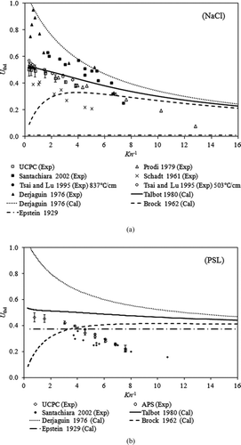
For NaCl particles (shown in ), our experimental setup was similar to that used by Tsai and Lu (Citation1995), and the dimensionless thermophoretic velocities derived from both works were reasonably fitted by EquationEquation (3) from Talbot et al. (Citation1980), although the performance of a plate-to-plate precipitator was characterized in the work of Tsai and Lu (Citation1995). Large scatter in the dimensionless thermophoretic particle velocity for NaCl particles is evident when plotting the data collected in our study and published in the literature in the same figure. The large variation may be due to the use of different particle generation methods, the polydispersity of test particles, the design of thermal precipitators, and measurements of particle size and concentration. As noticed in , none of the previously proposed formula can accurately fit the experimental data for large NaCl particles. However, the discrepancy between the experimentally derived and calculated dimensionless thermophoretic particle velocities for NaCl particles was less than that for PSL particles. In the works of Talbot et al. (Citation1980) and Tsai and Lu (Citation1995), the dimensionless thermophoretic velocity formula (EquationEquation (3)) proposed by Talbot et al. (Citation1980) was verified. The good agreement with our experimental data was also obtained for NaCl particles with the diameters less than 500 nm. However, for the cases of NaCl particles larger than 500 nm in diameter, EquationEquation (3) does not give a good fit to the experimental data collected by Prodi et al (Citation1979) and in our study. The poor fitting of EquationEquation (3) was also observed for PSL particles having the sizes larger than 500 nm. Sagot et al. (Citation2009) measured the thermophoretic velocity in air (k p/k g = 10) of vegetable oil droplets of large sizes by passing the droplet stream in an annular gap between two walls maintained at different temperature gradients. The work of Sagot et al. (Citation2009) also showed that Talbot's model over-estimates thermophoretic particle velocities in the transition regime.
Significant linear relationships of the dimensionless thermophoretic particle velocity as a function of Kn −1 were also found in our experiment. The regression of our data together with that published in the selected literature (Prodi et al. Citation1979; Tsai and Lu Citation1995; Santachiara et al. Citation2002) is shown in . The selection of previous works included in is based on either that the experimental condition in the studies is similar to ours or they are widely cited. Our experimental data and those published in the literature indicate that the dimensionless thermal velocities of NaCl and PSL particles had good linear relationships with Kn −1 and their fitting curves were close to each other. The similar phenomenon was also reported by Santachiara et al. (Citation2002) that the thermophoretic particle velocity depends only on the particle Knudsen number, not on the gas/particle conductivity in the transition region.
FIG. 8 The linear relationship between the dimensionless thermophoretic velocity (U thd) and Kn −1. (a) NaCl particles and (b) PSL particles.
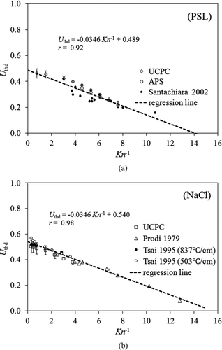
Bakanov (Citation1991) proposed the dimensionless thermophoretic velocity of particles at a low Knudsen number to be calculated as:
FIG. 9 Plot of the dimensionless thermophoretic velocity (U thd) vs. Knudsen number for PSL particles and regression line.
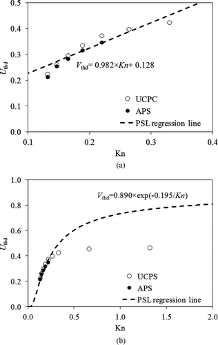
Schmitt (Citation1959) proposed an empirical exponential relationship for the dimensionless thermophoretic particle velocity in the Kn range of 0 ≤ Kn ≤ 5, which could be rewritten as expressed as:
FIG. 10 Plot of the dimensionless thermophoretic velocity (U thd) verses Kn −1 for NaCl, fluorescein sodium (F-Na), PSL, wax, and Ag particles.
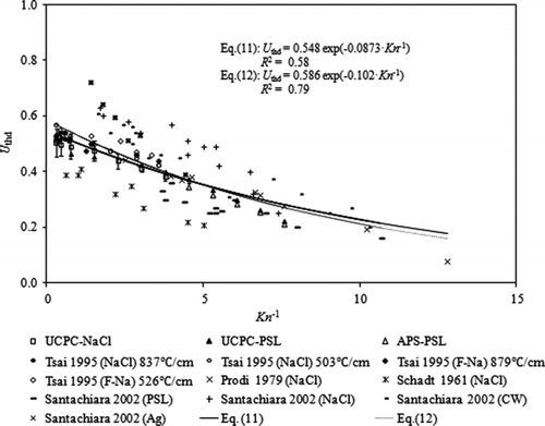
5.3 Last Remark on the Particle Collection Efficiency of the Thermal Precipitator
We note that the analytical model to estimate the particle collection efficiency of cylindrical thermal precipitators (EquationEquation (8)) is similar to that given by Tsai and Lu (Citation1995) for plate-to-plate type precipitators, which is determined by the collection area of the cold plate (A cold), the thermophoretic velocity (U thd), and the inlet airflow rate (Q in) under similar assumptions. The experimentally determined dimensionless thermal velocities of NaCl particles in the size range from 40 nm to 500 nm in our study are very close to those obtained in Tsai and Lu (Citation1995) (as shown in ). This observation reveals that the thermophoretic particle collection efficiency of thermal precipitators is only slightly dependent on the precipitator configuration (plate-to-plate, disk-to-disk, and cylindrical). The general expression for the particle collection efficiency of thermal precipitators in any configuration can be written as:
6. CONCLUSION
In this study, a cylindrical thermal precipitator with a detachable size-selective inlet was designed, and its performance was investigated. Our performance evaluation was carried out in two parts: one determined the optimal size-selective inlet distance to the wall, and the other measured the thermophoretic precipitation of particles. Based on the calibration, the size-selective inlet had a particle cut-off curve, with a 50% cut-off Stokes number of 0.238, removing particles larger than 1 μm in diameter at an aerosol flow rate of 1.5 lpm. The investigation of thermophoretic precipitation was performed by replacing the size-selective inlet in the studied precipitator with the same tube without an orifice nozzle at the exit end. The particle collection efficiency of the prototype under two temperature gradients (320 and 500°C/cm) at three aerosol flow rates (1.0, 1.5, and 2.0 lpm) was measured using DMA-classified NaCl particles ranging from 40 nm to 500 nm, and PSL particles ranging from 100 nm to 1000 nm. For particles with diameters less than 300 nm, the thermophoretic collection efficiency of the prototype remained close to constant. The moderate size effect on the thermophoretic collection efficiency was however observed for particle with diameters larger than 300 nm (i.e., 15–25% efficiency drop as the particle size increases from 300 nm to 500 nm, and about 40% drop as the size increased to 1000 nm).
A simple analytical model was further developed to estimate the thermophoretic particle collection efficiency of the prototype. It was found from the analytical model that the thermophoretic collection efficiency was primarily determined by the thermophoretic velocity of particles, the aerosol flow rate, and the particle deposition area. The calculated particle collection efficiency due to thermophoresis, based on the developed model, was in reasonable agreement with the experimental data for particles with diameters less than 400 nm. A noticeable discrepancy between the measured and calculated thermophoretic particle collection efficiencies was observed for particles with diameters larger than 400 nm.
By summarizing our data and those published in the literature, it was found that the dimensionless thermophoretic particle velocity generally depends on the particle size, not on the particle thermal conductivity, especially for large particles. It was further found that the empirical formula proposed in our study could give reasonable fitting to the dimensionless thermophoretic particle velocity as a function of particle Knudsen number (ranging from 0.078 to 3.3) via the available data.
A close look at the formula to predict the thermophoretic particle collection efficiency of a thermal precipitator reveals that the performance of a thermal precipitator is not significantly influenced by the device configuration (e.g., plate-to-plate, disk-to-disk, or cylindrical ones). The aerosol flow rate, total particle precipitation area, and the dimensionless thermophoretic particle velocity are three key parameters for a thermal precipitator. The combination of EquationEquation (12) given in this work with the use of a proper formula for dimensionless thermophoretic particle velocity will provide general guidelines for the future design of thermal precipitators.
NOMENCLATURE
| C c | = |
Cunningham slip correction factor |
| C m | = |
velocity jump coefficient |
| C t | = |
thermal jump coefficient |
| C s | = |
thermal creep coefficient |
| D jet | = |
size selected jet diameter |
| d p | = |
particle diameter |
| D h | = |
hydrodynamic diameter |
| H | = |
space between hot and cold tubes |
| Kn | = |
Knudsen number |
| L | = |
cold tube length |
| Q in | = |
inlet airflow flow rate |
| R 1 | = |
cold tube radius |
| R 2 | = |
hot tube radius |
| Re | = |
Reynolds number |
| Stk | = |
Stokes number |
| Stk 50 | = |
Stokes number for 50% collection efficiency |
| T c | = |
cold tube temperature |
| T h | = |
hot tube temperature |
| ∇T | = |
temperature gradient |
| ∇Tr | = |
r-axial temperature gradient |
| ∇Tz | = |
z-axial temperature gradient |
| T | = |
particle temperature |
| U th | = |
thermophoretic velocity |
| U thd | = |
dimensionless thermophoretic velocity |
| Ur th Uz th | = |
thermophoretic velocities in the r- and z-directions |
| u ave | = |
average airflow rate through the precipitator |
| ur | = |
r-axial airflow velocity |
| uz | = |
z-axial airflow velocity |
| λ | = |
gas mean free path |
| μ | = |
air dynamic viscosity |
| ρ | = |
air density |
| v | = |
air kinematic viscosity |
| k g k p | = |
thermal conductivities of the air and particle |
| η th | = |
particle collection efficiency due to thermophoresis |
| η total | = |
total particle collection efficiency |
| η diff | = |
particle collection efficiency due to Brownian diffusion and other factors |
| η imp | = |
particle collection efficiency due to impaction of the size-selective inlet |
uast_a_704097_sup_26974950.zip
Download Zip (17.5 KB)Acknowledgments
Mr. Wang would like to express the deepest appreciation for the financial support provided by the China Scholarship Council, which enables him to work in the Particle Laboratory at Washington University in St. Louis. Thanks are also given to Mr. Qisheng Ou and Mr. Fei Xia for their advice in improving the experiment design and formula deduction. Mr. Yuzhong Zhang gave great assistance during the review of previous literature for experiment data and comparison.
[Supplementary materials are available for this article. Go to the publisher's online edition of Aerosol Science and Technology to view the free supplementary files.]
REFERENCES
- Azong-Wara , N. , Asbach , C. , Stahlmecke , B. , Fissan , H. , Kaminski , H. Plitzko , S. 2009 . Optimisation of a Thermophoretic Personal Sampler for Nanoparticle Exposure Studies . J. Nanopart. Res. , 11 : 1611 – 1624 .
- Bakanov , S. P. 1991 . Thermophoresis in Gases at Small Knudsen Numbers . Aerosol Sci. Technol. , 15 : 77 – 92 .
- Batchelor , G. K. and Shen , C. 1985 . Thermophoretic Deposition of Particles in Gas Flowing Over Cold Surfaces . J. Colloid Interface Sci. , 107 : 21 – 37 .
- Bräuner , E. V. , Mortensen , J. , Møller , P. , Bernard , A. , Vinzents , P. Wåhlin , P. 2009 . Effects of Ambient Air Particulate Exposure on Blood–Gas Barrier Permeability and Lung Function . Inhal. Toxicol. , 21 : 38 – 47 .
- Bredl , J. and Grieve , T. W. 1950 . A Thermal Precipitator for the Gravimetric Estimation of Solid Particles in Flue Gases . J. Sci. Instrum. , 28 : 21 – 23 .
- Brock , J. R. 1962 . On the Theory of Thermal Forces Acting on Aerosol Particles . J. Colloid Sci. , 17 : 768 – 780 .
- Chalupa , D. C. , Morrow , P. E. , Oberdörster , G. , Utell , M. J. and Frampton , M. W. 2004 . Ultrafine Particle Deposition in Subjects with Asthma . Environ. Health Perspect. , 112 : 879 – 882 .
- Davis , L. A. and Adair , T. W. III . 1975 . Thermal Force on a Sphere . J. Chem. Phys. , 62 : 2278 – 2285 .
- Derjaguin , B. V. , Rabinovich , Ya. I. , Storozhilova , A. I. and Scherbina , G. I. 1976 . Measurement of the Coefficient of Thermal Slip of Gases and the Thermophoresis Velocity of Large-Size Aerosol Particles . J. Colloid Interface Sci. , 57 : 451 – 461 .
- Dobbins , R. A. and Megaridis , C. M. 1987 . Morphology of Flame-Generated Soot as Determined by Thermophoretic Sampling . Langmuir , 3 : 254 – 259 .
- Dockery , D. W. , Pope , C. A. , Xu , X. , Spengler , J. D. , Ware , J. H. Fay , M. E. 1993 . An Association Between Air Pollution and Mortality in Six U.S. Cities . N. Engl. J. Med. , 329 : 1753 – 1759 .
- Epstein , P. S. 1929 . Zur Theorie des Radiometers [On the Theory of the Radiometer]. In German . Z. Physik. , 54 : 537 – 563 .
- Geiser , M. , Rothen-Rutishauser , B. , Kapp , N. , Schürch , S. , Kreyling , W. Schulz , H. 2005 . Ultrafine Particles Cross Cellular Membranes by Nonphagocytic Mechanisms in Lungs and in Cultured Cells . Environ. Health Perspect. , 113 : 1555 – 1560 .
- Hetland , R. B. , Cassee , F. R. , Refsnes , M. , Schwarze , P. E. , Låg , M. Boere , A. J. F. 2004 . Release of Inflammatory Cytokines, Cell Toxicity and Apoptosis in Epithelial Lung Cells after Exposure to Ambient Air Particles of Different Size Fractions . Toxicol. In Vitro , 18 : 203 – 212 .
- Hinds , W. C. 1999 . Aerosol Technology , New York : Wiley .
- Jacobsen , S. and Brock , J. R. 1965 . The Thermal Force on Spherical Sodium Chloride Aerosols . J. Colloid Sci. , 20 : 544 – 554 .
- Kethley , T. W. , Gordon , M. T. and Orr , C. Jr . 1952 . A Thermal Precipitator for Aerobacteriology . Science , 116 : 368 – 369 .
- Kim , S. , Jaques , P. A. , Chang , M. C. , Barone , T. , Xiong , C. Friedlander , S. K. 2001 . Versatile Aerosol Concentration Enrichment System (VACES) for Simultaneous in Vivo and in Vitro Evaluation of Toxic Effects of Ultrafine, Fine and Coarse Ambient Particles Part I: Development and Laboratory Characterization . J. Aerosol Sci. , 32 : 1281 – 1297 .
- Krewski , D. , Burnett , R. T. , Goldberg , M. S. , Hoover , K. , Siemiatycki , J. Abrahamowicz , M. 2000 . “ Reanalysis of the Harvard Six Cities Study and the American Cancer Society Study of Particulate Air Pollution and Mortality. A Special Report of the Institute's Particle Epidemiology Reanalysis Project.Special Research Report ” . Cambridge , MA : Health Effects Institute .
- Li , N. , Sioutas , C. , Cho , A. , Schmitz , D. , Misra , C. Sempf , J. 2003 . Ultrafine Particulate Pollutants Induce Oxidative Stress and Mitochondrial Damage . Environ. Health Perspect. , 111 : 455 – 460 .
- Lorenzo , R. , Kaegi , R. , Gehrig , R. , Scherrer , L. , Grobéty , B. and Burtscher , H. 2007 . A Thermophoretic Precipitator for the Representative Collection of Atmospheric Ultrafine Particles for Microscopic Analysis . Aerosol Sci. Technol. , 41 : 934 – 943 .
- Marple , V. A. and Willeke , K. 1976 . Impactor Design . Atmos. Environ. , 10 : 891 – 896 .
- Messerer , A. , Niessner , R. and Pöschl , U. 2003 . Thermophoretic Deposition of Soot Aerosol Particles under Experimental Conditions Relevant for Modern Diesel Engine Exhaust Gas Systems . J. Aerosol Sci. , 34 : 1009 – 1021 .
- Montassier , N. , Boulaud , D. and Renoux , A. 1991 . Experimental Study of Thermophoretic Particle Deposition in Laminar Tube Flow . J. Aerosol Sci. , 22 : 677 – 687 .
- Montassier , N. , Boulaud , D. , Stratmann , F. and Fissan , H. 1990 . Comparison Between Experimental Study and Theoretical Model of Thermophoretic Particle Deposition in Laminar Tube Flow . J. Aerosol Sci. , 21 : 85 – 88 .
- Orr , C. and Martin , R. A. 1958 . Thermal Precipitator for Continuous Aerosol Sampling . Rev. Sci. Instrum. , 29 : 129 – 130 .
- Osornio-Vargas , A. R. , Bonner , J. C. , Alfaro-Moreno , E. , Martínez , L. , García-Cuellar , C. , Ponce-de-León Rosales , S. , Miranda , J. and Rosas , I. 2003 . Proinflammatory and Cytotoxic Effects of Mexico City Air Pollution Particulate Matter in Vitro are Dependent on Particle Size and Composition . Environ. Health Perspect. , 111 : 1289 – 1293 .
- Patel , M. M. and Miller , R. L. 2009 . Air Pollution and Childhood Asthma: Recent Advances and Future Directions . Curr. Opin. Pediatr. , 21 : 235 – 242 .
- Pope , C. A. 3rd and Dockery , D. W. 2006 . Health Effects of Fine Particulate Air Pollution: Lines That Connect . J. Air Waste Manage. Assoc. , 56 : 709 – 742 .
- Prodi , F. , Santachiara , G. and Prodi , V. 1979 . Measurements of Thermophoretic Velocities of Aerosol Particles in the Transition Region . J. Aerosol Sci. , 10 : 421 – 425 .
- Romay , F. J. , Takagaki , S. S. , Pui , D. and Liu , Y. H. 1998 . Thermophoretic Deposition of Aerosol Particles in Turbulent Pipe Flow . J. Aerosol Sci. , 29 : 943 – 959 .
- Sagot , B. , Antonini , G. and Buron , F. 2009 . Annular Flow Configuration with High Deposition Efficiency for the Experimental Determination of Thermophoretic Diffusion Coefficients . J. Aerosol Sci. , 40 : 1030 – 1049 .
- Santachiara , G. , Prodi , F. and Cornetti , C. 2002 . Experimental Measurements on Thermophoresis in the Transition Region . J. Aerosol Sci. , 33 : 769 – 780 .
- Schadt , C. F. and Cadle , R. D. 1961 . Thermal Force on Aerosol Particles . J. Phys. Chem. , 65 : 1689 – 1694 .
- Schlichting , I. I. 1979 . Boundary-Layer Theory , (7th ed.) , New York : Mc-Graw-Hill .
- Schmitt , K. H. 1959 . Untersuchungen an Schwebstoffteilchen im Temperaturfeld [Investigation of Suspended Particles in the Temperature Field]. In German. Z. Naturforsch. . 14a : 870 – 881 .
- Stratmann , F. and Fissan , F. 1989 . Experimental and Theoretical Study of Submicron Particle Transport in Cooled Laminar Tube Flow Due to Combined Convection, Diffusion, and Thermophoresis . J. Aerosol Sci. , 20 : 899 – 902 .
- Stratmann , F. , Otto , E. and Fissan , H. 1994 . Thermophoretical and Diffusional Particle Transport in Cooled Laminar Tube Flow . J. Aerosol Sci. , 25 : 1305 – 1319 .
- Talbot , L. , Cheng , R. K. , Schefer , R. W. and Willis , D. R. 1980 . Thermophoresis of Particles in a Heated Boundary Layer . J. Fluid Mech. , 101 : 737 – 758 .
- Tsai , C. J. and Lu , H. C. 1995 . Design and Evaluation of a Plate-to-Plate Thermophoretic Precipitator . Aerosol Sci. Technol. , 22 : 172 – 180 .
- Waldmann , L. 1959 . Uber Die Kraft Eines Inhomogen Gases auf Kleine Suspendierte Kugeln [The Force on Suspended Particles in Inhomogeneus Gas]. In German . Z. Naturforsch. , A14 : 589 – 599 .
- Waldmann , L. and Schmitt , K. 1966 . Aerosol Science , 137 – 162 . New York : Academic Press .
- Wang , B. , Ou , Q. S.M , Tao , S. and Chen , D. R. 2012 . Performance Study of a Disk-to-Disk Thermal Precipitator . J. Aerosol Sci. , 52 : 45 – 56 .
