Abstract
In the growing field of nanotechnology there is an increasing need to develop production methods for nanoparticles, especially methods that provide control and reproducibility. The spark discharge generator (SDG) is a versatile device for the production of nanoparticle aerosols. It can produce aerosol nanoparticles in the entire nanometer range (1–100 nm), and beyond. Depending on requirements, and the system used, these nanoparticles can be completely contamination free and composed of one or more materials. This provides a unique opportunity to create new materials on the nanoscale. Already in use in semiconductor, materials, health and environmental research, the SDG shows promise for yet more applications. If needed, particle production by the SDG could be scaled up using parallel generators facilitating continuous high-volume production of aerosol nanoparticles. Still, there is a surprisingly low knowledge of fundamental processes in the SDG. In this article we present a thorough review of the most common and relevant SDGs and the theory of their operation. Some possible improvements are also discussed.
Copyright 2012 American Association for Aerosol Research
1. INTRODUCTION
As early as the Enlightenment humankind began to take a scientific interest in aerosols, starting with atmospheric aerosols produced by earthquakes, lightning, meteoric dust, and combustion processes. In 1820, Rafinesque postulated: “dusty particles may be formed in the great chemical laboratory of our atmosphere” (Preining and Davis Citation2000). Seventy-eight years later, in 1898, one of the earliest patents for a spark plug saw the light of day in a patent registration from Nikola Tesla (Tesla Citation1898). Back then no one could know how these two fields would unite.
The need for nanoparticles in science and technology is constantly increasing, in fields ranging from semiconductor research and industry to environmental research. Nanoparticles are of interest because of their size-dependent properties and because the potential for their use is enormous, including as materials for storage in information technology (IT), in sensor applications, refractory materials, pharmaceuticals, catalysis, and novel materials, among others (Kruis et al. Citation1998).
There are several methods to produce nanoparticles for both scientific and industrial uses. A process widely used in industry for producing ceramic nanoparticles is flame spray pyrolysis (FSP). This process provides ceramic nanoparticles with a high purity and narrow size distribution at a high production rate. The method requires a burner for cracking the precursors, which, in most cases, needs to have physical properties (such as vapor pressure) that are not too dissimilar. To produce non-oxide nanoparticles, postprocessing is most often required (Pratsinis Citation1998). Another method is spray protolysis (SP), a simple and rapid process used for production of high purity nanoparticles with a high production rate. The process provides continuous synthesis of nanoparticles with controlled size, a narrow size distribution, high crystallinity, and good stoichiometry (Okuyama and Lenggoro Citation2003). A drawback could be the need for precursors and solutes that might contaminate the process.
The most commonly applied method in the chemical field is the use of colloids. Colloids have been used for a long time (Svedberg and Tiselius Citation1928), are well proven, and are readily available off the shelf. A disadvantage of this method is that solvent and precursor residues may be left on the substrate along with the nanoparticles, something not desired in nanofabrication. Electrospray (Meesters et al. Citation1992; Lenggoro et al. Citation2002) is a method for deposition of colloidal particles in a controlled homogenous manner that minimizes the residues where they are still present. The method has an easy setup with commercial machinery (Böttger et al. Citation2007).
Physical methods of aerosol production include evaporation/condensation of material and aerosol generation by spark discharge. The evaporation/condensation method (Scheibel and Porstendörfer Citation1983) has a good yield and offers detailed control over deposition parameters. However, the major drawback of this method, compared with spark discharge, is the furnace energy consumption and practical issues, like heating up and cooling down times (F. E. Kruis, personal communication, 22 September 2010). The time needed to heat up and cool down the furnace if a change of materials is desired is problematic, as is clogging of the furnace due to particle deposition on the walls. Both effects limit the operation time of the generation system.
The use of a spark discharge generator (SDG) for production of aerosol particles has several advantages compared to other methods. It is simple and has a reasonable yield that easily could be improved using parallel SDGs. Additionally, the method allows for higher surface purity (Tabrizi et al. Citation2009a), a property that is very important when it comes to nanoparticles, which have a large surface-to-volume ratio and therefore are potentially more reactive than bulk material. The SDG was first presented in 1988 (Schwyn et al. Citation1988) and was initially used to produce monodisperse carbon and gold nanoparticles. Later, the method was expanded into the broad range of usage found today.
2. THE PRINCIPAL DESIGN
In order to use the principle of spark discharge for nanoparticle production, an apparatus has to be designed that contains two components: a chamber to house the electrodes in the desired atmosphere and an electric circuit to control the spark generation. We will here describe the main components in a general manner.
The general design of the SDG consists of two opposing electrodes separated by a gap. The two electrodes can be either of the same material or of different materials. By charging a shunted capacitor, a high voltage is applied across the gap. When the capacitor reaches a sufficient voltage, a spark discharges over the electrode gap. The spark evaporates material from the electrodes and an aerosol forms. If different materials are used in the two electrodes, a composite aerosol will form. The aerosol is transported away from the gap by means of a carrier gas. The SDG is often used together with a neutralizer, as well as a differential mobility analyzer (DMA), scanning mobility particle sizer (SMPS), or a tandem DMA setup to control the particle generation.
2.1. The Chamber
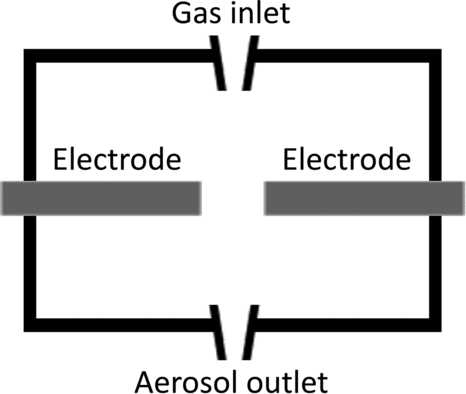
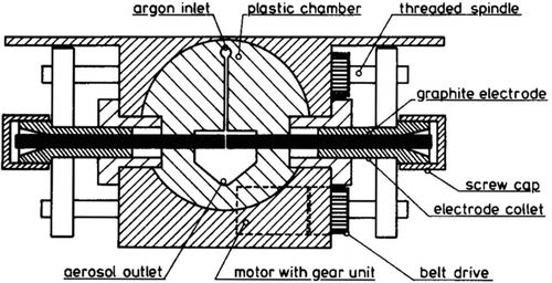
The chamber of a SDG is a housing for the electrodes, and the gap between them, that is connected to a carrier gas and aerosol handling system as seen in . The actual geometry of the chamber may play a minor role for aerosol production, although one could easily imagine that a geometry allowing for a laminar carrier gas flow and controlled coagulation of the created particles would be advantageous. Most existing SDG chambers have an open geometry, e.g., a stainless steel vacuum cross that certainly allows for turbulence in the gas flow. Since a high voltage will be applied to the electrodes, care has to be taken to isolate the electrodes from the housing. The chamber housing is normally constructed either of an insulating material or of a grounded metal chamber without any electrical contact to at least one of the electrodes. The choice of material may also be of importance. The distances between the housing and the high-temperature region of the spark are normally large and the gas flow is normally sufficiently high that the housing material is kept at room temperature or just slightly above. However, there can still be some outgassing from more volatile materials if they are used in the chamber lining (W. G. Kreyling, personal communication, 20 January 2009; Messing Citation2011).
FIG. 1 The basic components of the spark discharge generator chamber.
2.2. The Electrical System
In addition to the spark chamber, an electrical system is needed to provide the necessary voltage. It can be modeled as a simple resistance, capacitance, and inductance (RCL) circuit as shown in . Note that depicts just one common example; other circuits can be used as well (e.g., where the voltage source is replaced with a power source).
FIG. 2 The basics of the electrical system.
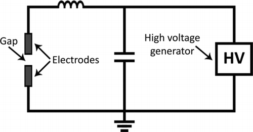
The high voltage generator is used to charge the capacitor and this provides the energy of the spark. The inductance in the system arises from the cabling and has an influence on the spark duration (Tabrizi et al. Citation2009a). The gap in between the electrodes can be modeled as a simple resistance with fair agreement to real systems (Tabrizi et al. Citation2009a). In order to prevent any damage to the the high voltage generator it may be necessary to place a diode between the generator and the capacitor, thereby ensuring that the discharge current is led through the electrodes.
3. THEORY
This chapter explains the processes and parameters involved in producing nanoparticle aerosols by spark discharge. These include spark formation and discharge, the effects of carrier gas flow, inter-particle interactions such as coalescence and coagulation, as well as the electrical properties of the generated particles. For a more extensive description of the theory behind spark discharge generation, see the excellent report by Tabrizi et al. (Citation2009a).
3.1. The Spark
For a spark discharge to occur across a gap, a high electric field is needed. At standard temperature and pressure (STP), with no applied electric field, gases are usually good insulators. Air permits current densities of 10−16–10−17 A/cm2 at low fields, e.g., in a normal office or apartment (Kuffel et al. Citation2000). Under these conditions, the naturally occurring ionization of molecules in the gas (caused by, for example, background radiation) makes little difference. The energy of the ejected electrons under these conditions is so small that they will not ionize other gas molecules when they collide with them. In a high electric field however, the accelerated electrons and cations will gain sufficient energy to ionize further gas molecules between the electrodes. If the field is high enough, the acceleration will give the electrons and cations the necessary energy to knock out electrons from multiple gas molecules. One single electron can then release several other electrons and these can in turn knock out several more electrons each. This will give rise to an electron avalanche and the formation of a conducting plasma channel, where charge can be carried by the released electrons and a current will flow between the electrodes. In addition, ejection of electrons will occur from the electrodes themselves when they are bombarded by cations and electrons. The plasma channel is the prerequisite for the spark and the spark itself is the resulting brief flow of current within that channel.
This process also generates X-rays with energies below 10 keV, so called soft X-rays (Va’vra et al. Citation1998). These X-rays are not powerful enough to penetrate the chamber walls, and no radiation has been reported from any of the setups tested.
The breakdown of the isolating gas is governed by Paschen's law. The breakdown voltage V b is given by EquationEquation (1):
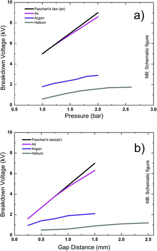
The material properties of different gases, i.e., A, B, and γ, influence the process as shown in . The use of argon or helium lowers the breakdown voltage compared to air. If nitrogen is used as carrier gas, the curve falls in between the theoretical Paschen curve and that measured for air. As predicted, the pressure of the gas has a direct effect on the breakdown voltage as seen in , as does the gap distance (), where a smaller electrode gap gives a lower breakdown voltage.
FIG. 3 (a) Effect of pressure on breakdown voltage (1 mm gap); (b) effect of gap distance on breakdown voltage (1 bar). (Schematically after Tabrizi et al. (Citation2009a), with kind permission from Springer Science and Business Media.) (Color figure available online.)
As is seen in EquationEquation (1), the breakdown voltage is given as a function of pd – pressure times the electrode distance (Va’vra et al. Citation1998). From EquationEquation (1), a minimum breakdown voltage can be calculated. Plotting EquationEquation (1) for air, this minimum occurs at about 325 V for a pd of around 11 Pa mm ().
FIG. 4 The Paschen curve for air at STP (A = 12, B = 365, and γ = 0.02).
Another effect of Paschen's law is that it is possible for two values of pd to share the same breakdown voltage. This can be explained in terms of the mean free path of the accelerated electrons in the electrode gap. If the gap distance is lowered at a constant pressure from the point of minimum breakdown voltage, then more and more electrons will cross the gap without colliding and ionizing any gas molecules. At higher pd, after passing the minimum breakdown voltage, the opposite happens. The probability of the electrons colliding with a gas molecule is higher, but the energy that the electrons gain by acceleration between the collisions is lower than the minimum value of pd (Kuffel et al. Citation2000). The effects of the breakdown voltage will be discussed in Section 3.3.
When the conducting plasma channel is formed, a spark follows. This spark lasts for the order of a few microseconds and reaches a local temperature of between 20,000 K and 30,000 K (Reinmann and Akram Citation1997). At these high temperatures, evaporation of the electrode material is inevitable and a plume of gaseous electrode material will evaporate from the electrodes. This material will supersaturate the volume between the electrodes, which is followed by nucleation of particles of the electrode material or materials (Tabrizi et al. Citation2009a).
3.2. Particle Formation and Coagulation
The evaporated electrode material in the supersaturated cloud will nucleate due to adiabatic expansion (Hinds Citation1982; Tabrizi et al. Citation2009a), radiation, and thermal conduction below the evaporation temperature (Tabrizi et al. Citation2009a), and so will yield stable particles. At this stage of the process, the volume of interest is filled with a high concentration of small primary particles. They range in size, depending on material and conditions for the spark, from 1 nm to about 9 nm (Schwyn et al. Citation1988; Helsper et al. Citation1993; Weber et al. Citation1996; Horvath and Gangl Citation2003; Seipenbusch et al. Citation2003; Wittmaack Citation2007; Byeon et al. Citation2008; Messing et al. Citation2009; Tabrizi et al. Citation2009a).
Because of the high number concentration of primary particles in the volume, they will collide. This results in the particles coalescing, either partly (“necking”) or completely, if the temperature of the particles is sufficient. This is shown in the transmission electron microscope (TEM) images in and schematically in (Lehtinen and Zachariah Citation2002).
FIG. 5 TEM images of primary particles in agglomerates on carbon film. (a) A gold agglomerate; (b) an iron oxide agglomerate; (c) a palladium agglomerate; (d) tin oxide agglomerates. The scale bar in (a–c) is 10 nm, and in (d) is 50 nm.
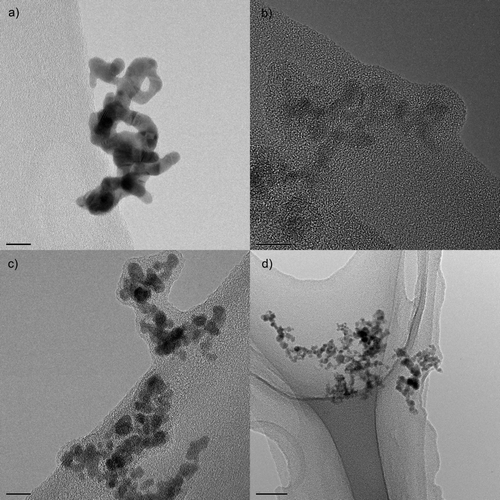
FIG. 6 The evolution of particle temperature and shape in nanoparticle coalescence. The decreasing surface area results in an energy release and, thus, an increase in temperature. (Reprinted from Lehtinen and Zachariah (Citation2002), with permission from Elsevier.)
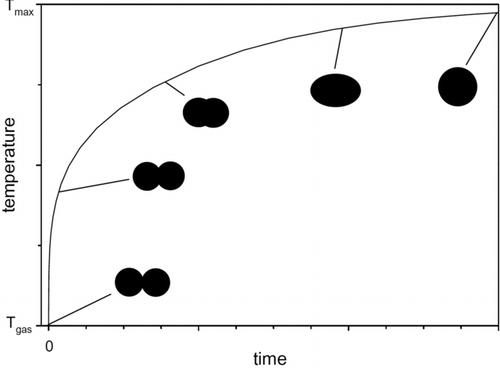
If the particle temperature is the same as the temperature of the surrounding gas, the particles will stick to each other (Hinds Citation1982; Lehtinen and Zachariah Citation2002). As they coalesce, the total surface energy will decrease, and if the time between collisions is smaller than the time it takes for the initial particles to cool to gas temperature, the temperature of the particles will increase (Lehtinen and Zachariah Citation2002). This will lead to more complete coalescence. If the coalescence is complete, a new spherical particle results, but when there is only partial coalescence, agglomerates form instead.
With rapid cooling of the aerosol volume, agglomeration increases—as the time between collisions of the primary particles becomes longer than the time it takes for the particles to cool down after a collision (Lehtinen and Zachariah Citation2002). In the case of the SDG, this will probably occur after the carrier gas has removed the primary particles from the electrode gap. Here, room temperature can be assumed for the gas as the increase in the available volume makes cooling very rapid. The volume increase also leads to a longer residence time for the particles, which also promotes coagulation. As already mentioned, coalescence is driven by a reduction in surface energy, which has the consequence that particles of extremely high purity can exhibit neck formation at room temperature—so called cold sintering (Tabrizi et al. Citation2009a). Although the resulting agglomerates have been studied (Messing Citation2011), the exact time and place where this process of nucleation and coagulation takes place within the SDG are not known.
3.3. Capacitance, Spark Frequency, and Energy
The frequency f of the spark is controlled by the charging current I of the capacitor (Schwyn et al. Citation1988). The relation is stated in EquationEquation (2):
The capacitance is also related to the energy E in the spark by EquationEquation (4),
FIG. 7 Effect of capacitance on the particle size distribution (d = 1 mm, f = 10 Hz, Q = 10 L/min, argon). (Schematically after Tabrizi et al. (Citation2009a), with kind permission from Springer Science and Business Media.) (Color figure available online.)
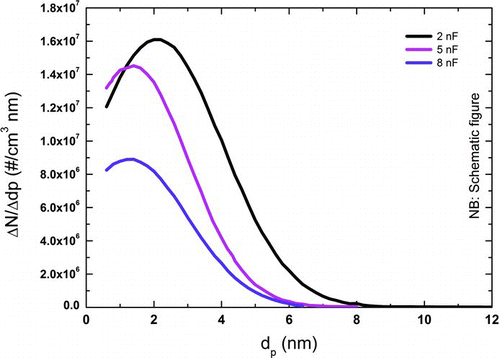
and show that with increasing capacitance the particle size distribution is shifted to larger particle sizes (Seipenbusch Citation2003; Tabrizi et al. Citation2009a).
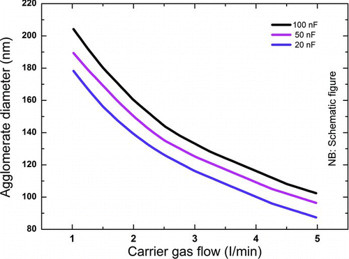
FIG. 8 The agglomerate diameter of platinum agglomerates as a function of the carrier gas flow for different capacitances. (Schematically after Seipenbusch (Citation2003).) (Color figure available online.)
There are indicators, however, that the amount of aerosol material produced is not in direct proportion to the energy as stated in EquationEquation (4) (Seipenbusch Citation2003). The level of supersaturation of the evaporated material in the volume between the electrodes will directly affect the primary particle diameter and number concentration. With a higher supersaturation there are more atoms that can cluster and nucleate, which leads to a higher number concentration. In addition, with more material in the supersaturated volume, the primary particles will grow larger before the aerosol has been cooled and diluted enough to prevent further growth.
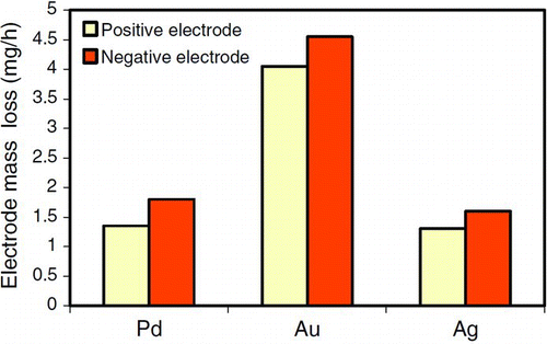
The electronics of the SDG gives rise to certain characteristics in the spark discharge. In most SDGs the discharge voltage oscillates, changing its polarity, for times varying from a few nanoseconds up to, at most, the entire duration of the spark, depending on the dampening in the electrical system (Reinmann and Akram Citation1997; Tabrizi et al. Citation2009a). This polarity change contributes to the mixing of the aerosols and is of importance when it comes to bimetallic aerosol generation in the SDG (Tabrizi et al. Citation2009b; Kala et al. Citation2011). The polarity change counteracts the fact that the cathode tends to erode more than the anode. This is expected since the positively charged ions that are accelerated to hit the cathode have more mass than the electrons hitting the anode (Tabrizi et al. Citation2009a,Citationb). If the oscillation is damped out there will be more material from the cathode in the aerosol. This is shown in where the mass losses of the anode and the cathode are compared for different materials without polarity changes. It is clear that there is higher mass loss from the cathode than from the anode. With polarity changes the losses are more even for the two electrodes, since both alternately act as anode and cathode.
FIG. 9 Electrode mass loss for gold, silver, and palladium (C = 20 nF, d = 1 mm, f = 120 Hz, Q = 1 L/min, Ar). (Reprinted from Tabrizi et al. (Citation2009a), with kind permission from Springer Science and Business Media.) (Color figure available online.)
3.4. Carrier Gas
As mentioned in Section 3.1, the choice of carrier gas has an effect on the energy of the spark. Additionally, the flow of the carrier gas is of importance in the SDG because the volume between the electrodes has to be cleared of particles between one spark and the next. Otherwise the sparks will not be identical, which leads to reproducibility problems and at the extreme, with no carrier gas flow, to formation of an aerogel in the spark chamber (Tabrizi et al. Citation2009a). The flow rate of the carrier gas has an effect on the size distribution of the nanoparticles produced. At lower flow rates, a broader size distribution with a larger mean diameter can be expected (Schwyn et al. Citation1988; Tabrizi et al. Citation2009a).
Tabrizi et al. have shown that for higher flow rates, above 5 L/min, the particle size remains more or less constant. This has been explained by two different growth domains. The first in a high concentration region between the electrodes, where the flow is assumed to be laminar and growth is limited by diffusion (Tabrizi et al. Citation2009a), although if the flow rate is high enough, dilution will limit the growth more than diffusion. The second growth domain is in a low concentration region after the particles have passed the electrode gap. In this region, growth is governed by turbulent mixing. Here, dilution is of greater importance than diffusion, causing this region to have only a small effect on particle formation (Tabrizi et al. Citation2009a).
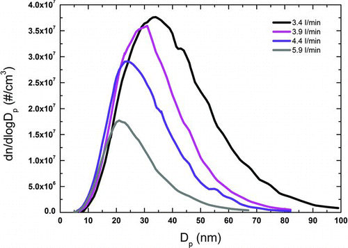
If the carrier gas flow purges the electrode gap of particles between successive sparks, each spark can be considered separately. It follows that the number concentration of particles is a linear function of the frequency (Helsper et al. Citation1993; Messing et al. Citation2009; Tabrizi et al. Citation2009a) provided that the dilution of the aerosol is sufficient to control coagulation of the primary particles. If the dilution is not sufficient the coagulation of the produced particles will also be affected by the carrier gas flow rate, as displayed in .
FIG. 10 Particle size distributions at different gas flow rates. (Color figure available online.)
3.5. Electrical Properties of the Generated Particles
Because formation of the nanoparticles in a SDG takes place in a plasma, the particles are expected to be charged. Tabrizi et al. present data on the electrical properties of the generated particles. By using an SMPS, particles were measured with respect to charge and concentration with and without a neutralizer. The particles are clearly charged. Up to 20% of the particles retain a negative charge, which is a significant increase from the bipolar charging that might be expected. The high probability of negatively charged particles is explained by precipitation of the positively charged particles on the walls of the grounded housing (Tabrizi et al. Citation2009a). The ultraviolet light and soft X-rays emitted from the spark itself can also be a source of charging (Barmpounis et al. Citation2011; Knobel and Schmid Citation2011).
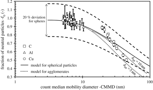
Bau et al. (Citation2010) studied the fraction of neutral particles of copper, aluminum, and graphite generated from a commercially available SDG (Palas model GFG 1000). In the setup, a radial-flow mobility analyzer (SMEC) was used in conjunction with a condensation nucleus counter (CNC) and an electrometer. Below 10 nm count median mobility diameter (CMMD), the fraction of neutral particles is close to 100% (). For carbon, the fraction of neutral particles decreases from 90% to 50% when the CMMD increases from 20 nm to 50 nm.
FIG. 11 Fraction of neutral particles f 0 as a function of the aerosol count median mobility diameter. (Reprinted from Bau et al. (Citation2010), with kind permission from Springer Science and Business Media.)
4. EXISTING SPARK DISCHARGE GENERATORS
There are a number of different approaches to aerosol generation by spark discharge. In this section, some of these will be presented along with their benefits and drawbacks.
4.1. Commercial
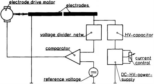
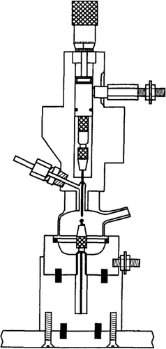
The GFG 1000 is to our knowledge the first commercially available SDG. It is developed based on the principal design as described above. It is designed for carbon aerosol generation and has been used extensively in material, environmental, and medical studies of aerosols of carbon and other materials (Helsper et al. Citation1993; Brown et al. Citation2000; Poschl et al. Citation2001; Oberdörster et al. Citation2002; Evans et al. Citation2003a,Citationb; Kuznetsov et al. Citation2003; Saathoff et al. Citation2003a,Citationb; Schnaiter et al. Citation2003; Kamm et al. Citation2004; Roth et al. Citation2004; Sadezky et al. Citation2005; Bitterle et al. Citation2006; Messerer et al. Citation2006; Muckenhuber and Grothe Citation2007; Muller et al. Citation2007; Wittmaack Citation2007; Lu et al. Citation2008; Messing et al. Citation2009; Messing et al. Citation2010). The GFG 1000 is a safe, robust system that can simply be connected to an experimental setup and used. The main feature of the system is the automatic, constant discharge voltage adjustment. This is accomplished by continuously comparing the voltage between the electrodes with a reference voltage. The gap between the electrodes is then adjusted with the help of electrical motors so that the discharge voltage matches the reference voltage (Helsper et al. Citation1993).
This feature enables continuous operation over prolonged periods of time without the need to adjust the gap distance. Another feature of the GFG 1000 is the possibility to dilute the aerosols directly at the end of the spark chamber, at the aerosol outlet shown in . The system is developed for the use of argon gas injected between the electrodes, with the use of clean air for dilution. This makes it possible to halt further coalescence of the carbon aerosols at an early stage of the agglomeration process.
FIG. 12 Mechanical arrangement of the GFG 1000. (Reprinted from Helsper et al. (Citation1993), with permission from Elsevier.)
In the electrical system of the GFG 1000, as seen in , the capacitance of the system is 20 nF and the reference voltage is set so that the discharge voltage is 2 kV. These parameters give an energy in each spark of 40 mJ. The charging current can be adjusted by a scale knob between 1 and 1000, which corresponds to a charging current between 0.13 mA and 20 mA. This in turn gives spark discharge frequencies of between 2 Hz and 300 Hz (Helsper et al. Citation1993).
FIG. 13 Electrical supply and control circuit of the GFG 1000. (Reprinted from Helsper et al. (Citation1993), with permission from Elsevier.)
Often the argon carrier gas is substituted with nitrogen gas of high purity for economical reasons. However, this change in the carrier gas causes the energy of the spark to increase as seen in . This will, in conjunction with the GFG 1000 automatic spark energy adjustment, make the electrode gap smaller, in accordance with EquationEquation (4). The decreased electrode gap may have some effect on the flow of particles if the carrier gas cannot purge the electrode gap so effectively because of higher flow resistance. In practice though, this does not play a large role.
The drawbacks of the GFG 1000 SDG are that the chamber is made out of plastic and is not leak-tight, which makes contamination by hydrocarbons a possibility (W. G. Kreyling, personal communication, 20 January 2009; Messing et al. Citation2010). In addition the system consists of a single unit to ensure safe handling of the high voltage. Because the electrical system is integrated into the unit, the ability to measure operating voltages is restricted and the settings that can be chosen are limited. These drawbacks stem from the fact that the system is not intended for the production of metal nanoparticles.
That the chamber is not leak or gas tight is due to the gas connectors used in the system and the chamber sealing, which both make it possible for oxygen to diffuse into the chamber in small quantities. These quantities, in addition to the small amounts of oxygen usually found in nitrogen gas, are enough to at least partially oxidize the most sensitive metals such as nickel (Messing Citation2011). The other drawback of limited settings is due to the automation of the system. It is not possible to change the spark distance and spark energy manually. This limits to some extent the size range of aerosols that can be produced. These limitations are largely due to the difficulty of measuring the discharge voltage. The electrodes are placed inside the device; there are no direct ways to contact the electrodes to perform measurements, and there is no window to visually investigate the electrode gap. The system has to be shut down and the chamber opened to determine the distance between the electrodes. The placement of the electrodes also makes changing electrodes relatively complicated.
In recent years Palas has presented new models with the GFG 1000 as a base. The GFG 3000 uses mass flow controllers (MFCs) for gas flow control and has a variable voltage from 0.5 kV to 2.6 kV. The DNPs 1000 and 3000 are made for nitrogen as a carrier gas instead of argon. The DNP 3000 also uses MFCs and has a variable voltage of 2 kV to 4.3 kV. All models can be fitted with a ceramic chamber.
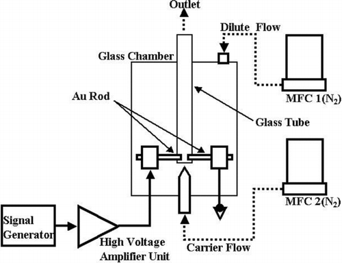
Another commercial SDG is the APG-200 from the Japanese company Sibata Technology Ltd., shown schematically in . It is a SDG designed for production of gold particles smaller than 10 nm. It consists of two electrodes in a linear facing geometry with a perpendicular gas flow. The chamber is made of a borosilicate glass cylinder with the additional feature of an inner tube of the same material. The gas flow is directed at the electrode gap by means of a nozzle, and a dilution gas flow is added to the chamber with the only evacuation path being past the electrodes. The design is specified for nitrogen gas with a carrier gas flow of 0.08–2.0 L/min and a dilution gas flow of 0.1–5.0 L/min. The high voltage supply can provide a maximum voltage of 2 kV and a spark frequency of 10–1000 Hz. The particles were found to be in the sub-10-nm range with a particle concentration around 108 particles/cm3. It is stated that a non-linear relation was found between frequency and particle concentration. This might be due to the low gas flow used during the experiments. Flows of 0.6 L/min and 0.4 L/min for carrier and dilute gas flow, respectively, were used.
FIG. 14 Schematic of the AGP-200 from Sibata (SIBATA).
4.2. Other Designs
The SDGs described in this part are constructed and/or operate in a different manner from the principal design, although they are based on the same theory and governed by the same parameters.
4.2.1. Tubular Spark Discharge Generator
A research group at Karlsruhe Institute of Technology has developed a prototype SDG that is quite different from the original design. By placing the electrodes in a tube parallel to the carrier gas flow, they eliminate any misalignment of the carrier gas inlet and the electrode gap. It is not yet determined if the transport of aerosols from the gap between the electrodes is efficient enough to completely remove the aerosols between sparks, or whether the flow can be considered laminar between the electrodes.
To change the electrode distance, the long electrode in is first put in physical contact with the opposing, shorter electrode. The long electrode is then retracted the desired distance. The capacitance is charged by a Fug HCK 100—20,000 capacitance charger. This setup yields a number concentration of ∼107 cm−3 (M. Seipenbusch, personal communication, 17 March 2009).
FIG. 15 The tubular SDG in Karlsruhe, Germany (image courtesy of M. Seipenbusch).
4.2.2. High Pressure Cold Plasma Spark Discharge Generator
In this SDG, a pressure of the order of 10,100 Pa is used in the spark chamber, which can be considered high for working with a cold plasma. The electrodes are in a point-to-plane configuration, as shown in , with the point electrode of either stainless steel or tungsten carbide having a radius of 50 μm to 100 μm. The plane electrode is made out of a grounded platinum grid positioned 1–2 cm from the point electrode (Borra et al. Citation1998). Between the point and plane, a potential difference of ±30 kV is applied.
FIG. 16 Synoptic view of the experimental setup. (Reprinted from Borra et al. (Citation1998), with permission from Elsevier.)
Different regimes of the plasma between the electrodes were investigated. It was found that different applied voltages lead to different behaviors in terms of both current and nanoparticle production. In the regime where the voltage is below the breakdown voltage there was nanoparticle production up to a particle concentration of 103 cm−3, and in the regime above that, where sparks propagate, up to 106 cm−3 (Borra et al. Citation1998). Production of nanoparticles is attributed to nucleation of metallic species produced by interactions between the plasma and the electrodes, through sputtering of the electrode surfaces and sublimation of the electrode by thermal effects.
4.2.3. Low Voltage Spark Discharge Generator
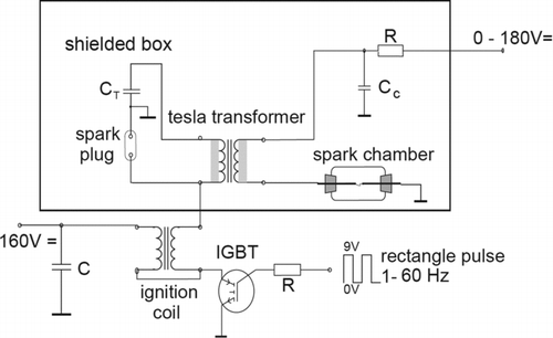
The low voltage SDG presented by Horvath and Gangl utilizes a Tesla transformer to trigger the main spark with a short, high frequency, high voltage pulse that produces a very weak primary spark (Horvath and Gangl Citation2003).
This primary spark from the Tesla transformer ionizes the gas between the electrodes and facilitates the generation of the main spark. When using this spark generator, schematically presented in , the charge voltage can be kept below 200 V, making it safer to handle the system. The Tesla spark can discharge across an electrode gap of up to 2 cm even at this low voltage, resulting in longer runtimes without the need to adjust the electrodes. With the lower charge voltage a lower energy per spark is obtained, according to EquationEquation (4). This results in a lower yield of aerosols: the number concentration of aerosols produced by this SDG is in the order of 104 cm−3 (Horvath and Gangl Citation2003).
FIG. 17 Spark generator using a Tesla transformer. (Reprinted from Horvath and Gangl (Citation2003), with permission from Elsevier.)
4.2.4. Spark Ablation Cell
This spark-based, solid sampling cell was developed for generating aerosols for sampling with inductively coupled plasma mass spectrometry (ICP-MS) (Vanhoven et al. Citation1995). It uses a 17 kV electronic adjustable waveform power supply. This is a much higher voltage than is used in all the other SDGs presented in this article. The higher voltage manifests itself in the higher production of aerosols. With a setting of 45% power and a argon carrier gas flow of 1.2 L/min, a mass transport of 12 μg/s was recorded using gold and silver samples and a tungsten counter electrode (Vanhoven et al. Citation1995). This can be qualitatively compared to a loss of mass from the electrodes of 3 μg/s (11 mg/h) at 0.8 L/min reported by Tabrizi et al. (Citation2009a). It should be noted that the frequencies were different, 480 Hz for the spark ablation cell (SAC) and 150 for the SDG. The gap distances were also different, 3 mm for the SAC and 1 mm for the SDG. All parameters considered, it is fair to say that the production rate of the SAC is probably as good as the SDG. shows many of the differences in construction to the regular SDGs. The main feature is the upper ablation chamber made of borosilicate glass. This allows for study of the spark and visual control of the electrode gap. The borosilicate glass chamber is also free from corners that create dead space with recirculation of aerosols (Vanhoven et al. Citation1995). This construction is a mix of the normal SDG and the tubular SDG.
FIG. 18 Schematic diagram of the spark ablation cell. (Reprinted from Vanhoven et al. (Citation1995), with permission from Elsevier.)
4.3. Improvements for the Spark Discharge Generator
The SDGs discussed earlier can still be improved. In this part, a few general improvements are discussed.
4.3.1. Laminar Gas Flow
Using a laminar flow through the spark chamber might have several positive effects, such as a higher yield of smaller particles and the production of particles with a more narrow size distribution. One effect of laminar flow would be that mixing would only take place by diffusion. Aerosol particles at the nanoscale (<100 nm) have much higher diffusion rates than particles at the micro or macro scale. Because of this, losses due to diffusion could be an important issue in a system with nanoparticles. Fortunately, the terminal settling velocity is very low, in the order of 10−7 cm/s to 10−5 cm/s (Hinds Citation1982), which leads to the valid assumption that the nanoparticles will follow the carrier gas flow and the system will not be subject to any major settling or impact losses. The new design by the group in Karlsruhe as described in Section 4.2.1 is a step in this direction.
4.3.2. Adjustable Electrical System
To achieve full flexibility, and thereby make optimum results possible, a fully adjustable electrical system is required. It is also beneficial to make the electrical system separate from the spark chamber. In this way the chamber can be easily replaced, and changing the electrical system does not require the spark chamber to be altered.
The capacitance and inductance of the system should be variable, since that would ensure that an optimum for aerosol production could be found. The capacitance determines the spark energy while the inductance has an influence on the spark duration. If the duration of the spark is longer than the duration of electrode heating, more material is evaporated (V. A. Vons, personal communication, 19 March 2009). The usage of different capacitances has been tested quite thoroughly (Schwyn et al. Citation1988; Horvath and Gangl Citation2003; Seipenbusch et al. Citation2003; Tabrizi et al. Citation2009a) but the influence of the inductance needs to be investigated further.
4.3.3. Altered Electrode Geometry
As described earlier in this article and by Roth et al. (Citation2004) and Tabrizi et al. (Citation2009a), the size of the particles produced by SDGs can be controlled by varying the electrode gap distance, the spark frequency, the nature of carrier gas, and the carrier gas flow. However, there are some indications that altering the shape of the electrodes may also influence both the particle size and the size distribution.
As hinted in a figure in (Cole et al. Citation2009), sharpened electrodes were used when making sub-20-nm nanoparticles. Sharpening the electrodes to decrease the amount of material evaporated by each spark, could be a viable way to produce smaller particles.
Using a pin-to-plate geometry, as shown in , instead of the more commonly used geometry with two linearly opposing electrodes with a perpendicular carrier gas flow, has been reported to affect the outcome of particle generation by spark discharge (Lee et al. Citation2011). Indium-tin nanoparticles generated with the pin-to-plate geometry were about 30–60% smaller and had a narrower size distribution than those produced with the rod-to-rod geometry, even though the voltage, gas flow rate, electrode gap distance, and electrode materials were the same.
FIG. 19 The pin-to-plane geometry. (Reprinted from Han et al. (Citation2012).)
The pin-to-plate geometry had a significantly lower spark frequency than the rod-to-rod geometry, even though other parameters were constant. The difference in frequency follows from the increase in discharge voltage caused by the asymmetric geometry of the pin-to-plate configuration. With lower spark frequency less material is evaporated causing the particle size to decrease and the size distribution to become narrower. However, it is not clear if the particle size and the size distribution will change accordingly if the spark frequency of the rod-to-rod geometry is lowered to the same value as the spark frequency for the pin-to-plate geometry.
When the tip of the electrodes were proton-irradiated and used in a SDG by Kreyling et al., nanoparticles containing the radioactive isotope were produced (Kreyling et al. Citation2011). This leads to the assumption that the evaporated material essentially comes from the tip of the electrodes and that less material should be evaporated if the size of the tip is decreased. To validate this assumption, one could irradiate other areas of the electrodes and determine the presence of radioactive isotopes. This may also give a hint to the size of the area from which material is evaporated by the spark.
4.3.4. High Purity
As described previously, the distance between the zone of materials evaporation and the walls of the chamber should be sufficient to avoid any contamination of the generated particles by material from the walls. However, observations of possible contamination of as-generated particles by the plastic material in the GFG 1000 have led to the development of a new apparatus by Palas that contains a ceramic chamber (W. G. Kreyling, personal communication, 20 January 2009). Additionally, the research group at Delft University in the Netherlands has made considerable effort to produce nanoparticles with very high degree of purity. Their setup includes a chamber and gas tubing of clean stainless steel as well as using high purity gas that passes a purification system just before entering the chamber. With this apparatus, the group was able to fabricate nanoparticles of pure Mg, a nanomaterial known to oxidize when minute amounts of oxygen or water are present (V. A. Vons, personal communication, 19 March 2009).
5. APPLICATIONS
There are many applications for the SDG in a variety of fields. To date, those fields include aerosol science in collaboration with medicine and health, environmental science, and material science. The benefit of the SDG in terms of easy operation, control, and reproducibility is probably the main reason for this. In addition, the possibility to easily produce particles consisting of mixed elements (Tabrizi et al. Citation2009b) opens up for further applications, e.g., in the field of catalysis or electronics.
For environmental studies, such as atmospheric pollution, there is a need for laboratory production techniques for soot-like carbon nanoparticles. By using a SDG with carbon electrodes, agglomerates are formed from primary particles (Helsper et al. Citation1993). The chemical composition of the produced particles differs from real soot aerosols, but they are still a good model for the physical properties of combustion products. Real soot particles contain hydrocarbons and contamination from the more complex combustion situation, whereas the SDG particles will be pure carbon with little or no contamination.
Investigations of the possible health effects of ultrafine particles on humans are necessary to determine if such ultrafine particles have an intrinsic toxicity or, if there are any toxicological effects, if they are material related. Because of the large surface-to-volume ratio, ultrafine particles can act as carrier for toxic gases and chemicals into lungs (Roth et al. Citation2004). In addition, the shape and aspect ratio of the particles are also parameters to consider.
To this end, radioactive labeling of designed nanoparticles is one way of following them as they pass through the living organism. Proton irradiation in a cyclotron of the tip of a titanium electrode causes 48Ti atoms transform into radioactive 48V (Kreyling et al. Citation2011). When this electrode is used in the SDG, 48V particle isotopes are evaporated and incorporated into the nanoparticles. The nanoparticles are then heat treated in order to sinter the 48V isotopes into the nanoparticle before introducing them to an oxygen/nitrogen atmosphere, creating the desired 48V-TiO2 nanoparticles by oxidation.
Another method of radiolabeling particles is to soak the electrode tips in a solution of the label material (Brown et al. Citation2000). Brown et al. used graphite electrodes and Technetium-99m (99mTc), which is a gamma emitter, to label “soot-like” graphitic particles. This labeling method yields both location and amount information for use in human inhalation studies. The result shows aggregates with an activity median diameter (AMD) that can be varied between 50 nm and 150 nm. The larger aggregate size is accomplished with aging of the aggregates in a 100 L balloon after generation. The method has been approved for studies of the effect of nanoparticles in the human respiratory system (Brown et al. Citation2000).
Using nanoparticles from the SDG for catalysis is another application. The synthesis of methane from carbon monoxide and hydrogen over a nickel surface, in this case an aerosol, is well known and studied. During deposition of carbon atoms, this reaction can change the particle surface. Aerosol catalysis can not only be used for methanation, but also in industrial applications and atmospheric chemistry (Weber et al. Citation1999).
The SDG has also been used to produce palladium catalyst nanoparticles with a small size distribution for catalysis research (Messing et al. Citation2010). By using scanning electron microscope (SEM) and TEM, it was confirmed that the produced palladium particles had a narrow size distribution because of the tandem DMA setup used. With X-ray diffraction (XRD) and X-ray photoelectron spectroscopy (XPS), the particles were concluded to be crystalline Pd with an amorphous carbon shell. The shell probably originates from contamination in the SDG used and can be eliminated with a cleaner system. Particles can then be used as a model system for catalytic reactions by depositing them on a substrate before performing studies.
SDGs have also been used for nanomaterial production and patterning. Cole et al. (Citation2009) produced positively charged aerosol nanoparticles in a SDG with gold or zinc oxide electrodes. These particles were then collected on a conducting silicon substrate that was covered with a patterned resist (S1805). The charged nanoparticles were deposited in the openings of the resist because the resist was highly charged, and thus acted as an electrostatic nanolens. The self-assembled structures thus acquired differed depending on the deposition time and the charge of the particles. Also, Choi et al. (Citation2008) have used an electrostatic lens for self-assembling spark-generated aerosol particles.
Particles produced in the SDG are ideal as seed particles for nanowire growth (Messing et al. Citation2009). The particles produced are after treatment monodisperse, spherical, and clean, giving reproducible conditions that is important for semiconductor materials. The nanowires themselves have the potential to become the next generation in semiconductor technology in integrated circuits, solar cells, and light emitting diodes.
Soft X-rays with energies between 2 keV and 10 keV have been produced with a SDG (Va’vra et al. Citation1998). Parameters were set to maximize the production of X-rays for the various gases that were used. The X-rays were detected by four different types of detectors. A big advantage of this X-ray source is that it is triggerable. The soft X-rays can be used for imaging (Artyukov et al. Citation2010) and material characterization (Fadleys Citation2009). As mentioned in Section 3.1, these X-rays are not sufficiently powerful to penetrate the chamber walls.
6. CONCLUSION AND OUTLOOK
The SDG is a versatile and robust apparatus. The same simple principles used in a spark plug in an ordinary car are used, but in the lab the SDG offers much more control for particle production. There are several different approaches to the design of the SDG presented in this review. Most of these are custom made for specific research projects, but there are commercially available SDGs. All have their benefits and drawbacks, and the intention of this review has been to highlight their relative merits.
There are an increasing number of research groups using the SDG for their particular branch of research, ranging from radioactive labeling in health and environmental studies to material science investigations of novel materials for new electronics, semiconductor fabrication, or catalysis. It is still the case that not all of the principles of the spark discharge are fully understood or known. It is still not systematically investigated and known how the different electrical parameters influence the spark, aerosol formation, and charging of the aerosol. Also, there has been no systematic investigation into how pressure affects the spark and aerosol formation, especially at more extreme pressures. But mostly this holds true for the temporal and spatial nucleation of the product aerosol, and its coagulation. There is at present no published work on how nucleation and coagulation take place in these systems. Further studies are necessary to build models for a better understanding of these fundamental processes. By doing so, and by using the controlled environment of the SDG, we shall also gain knowledge about nucleation and coagulation processes in other fields, such as environmental aerosols. The SDG also has potential for mass production of nanoparticles of known or novel materials and material combinations. This can be accomplished by parallel processing with many SDG chambers. Even though the SDG yields a modest mass output, the demand for large quantities of nanoparticles need not arise. This is especially true of noble metals and other very expensive materials, where the possibility of making particles of nano size promises to lower material consumption.
LIST OF ACRONYMS
| AMD | = |
activity median diameter |
| CMMD | = |
count median mobility diameter |
| CNC | = |
condensation nucleus counter |
| FSP | = |
flame spray pyrolysis |
| ICP-MS | = |
inductively coupled plasma mass spectrometry |
| IT | = |
information technology |
| DMA | = |
differential mobility analyzer |
| MFC | = |
mass flow controller |
| RCL | = |
resistance, capacitance, and inductance |
| SAC | = |
spark ablation cell |
| SDG | = |
spark discharge generator |
| SEM | = |
scanning electron microscope/microscopy |
| SMPS | = |
scanning mobility particle sizer |
| SMEC | = |
spectromètre de mobilité electique circulaire (radial-flow mobility analyzer) |
| SP | = |
spray protolysis |
| STP | = |
standard temperature and pressure |
| TEM | = |
transmission electron microscope/microscopy |
| XPS | = |
X-ray photoelectron spectroscopy |
| XRD | = |
X-ray diffraction |
Acknowledgments
This work was performed within the Nanometer Structure Consortium at Lund University (nmC@LU), was supported by the Swedish Research Council (VR), and received funding from the European Union's Seventh Framework Program under Grant Agreement no. 280765 (BUONAPART-E). Parts of the work were preformed within the Engineering Nanoscience master program (Teknisk Nanovetenskap) at the Faculty of Engineering, LTH at Lund University. The authors thank Fangfang Yang for her help with some images.
Related Research Data
References
- Artyukov , I. A. , Feschenko , R. M. , Vinogradov , A. V. , Bugayev , Y. A. , Devizenko , O. Y. Kondratenko , V. V. 2010 . Soft X-Ray Imaging of Thick Carbon-Based Materials Using the Normal Incidence Multilayer Optics . Micron , 41 : 722 – 728 .
- Barmpounis , K. , Pfeiffer , T. V. , Vons , V. A. , Biskos , G. and Schmidt-Ott , A. 2011 . Self-Charge Distribution of Nanoparticles Generated by Spark Discharge , Manchester , , UK : Paper presented at the European Aerosol Conference .
- Bau , S. , Witschger , O. , Gensdarmes , F. , Thomas , D. and Borra , J. P. 2010 . Electrical Properties of Airborne Nanoparticles Produced by a Commercial Spark-Discharge Generator . J. Nanopart. Res. , 12 : 1989 – 1995 .
- Bitterle , E. , Karg , E. , Schroeppel , A. , Kreyling , W. G. , Tippe , A. Ferron , G. A. 2006 . Dose-Controlled Exposure of A549 Epithelial Cells at the Air-Liquid Interface to Airborne Ultrafine Carbonaceous Particles . Chemosphere , 65 : 1784 – 1790 .
- Borra , J. P. , Goldman , A. , Goldman , M. and Boulaud , D. 1998 . Electrical Discharge Regimes and Aerosol Production in Point-to-Plane DC High-Pressure Cold Plasmas: Aerosol Production by Electrical Discharges . J. Aerosol Sci. , 29 : 661 – 674 .
- Böttger , P. H. M. , Bi , Z. , Adolph , D. , Dick , K. A. , Karlsson , L. S. Karlsson , M. N. A. 2007 . Electrospraying of Colloidal Nanoparticles for Seeding of Nanostructure Growth . Nanotechnology , 18 : 105304
- Brown , J. S. , Kim , C. S. , Reist , P. C. , Zeman , K. L. and Bennett , W. D. 2000 . Generation of Radiolabeled “Soot-Like” Ultrafine Aerosols Suitable for Use in Human Inhalation Studies . Aerosol Sci. Tech. , 32 : 325 – 337 .
- Byeon , J. H. , Park , J. H. and Hwang , J. H. 2008 . Spark Generation of Monometallic and Bimetallic Aerosol Nanoparticles . J. Aerosol Sci. , 39 : 888 – 896 .
- Choi , M. , Lee , H. , You , S. and Woo , C. 2008 . Array Formation of 3-D Nanostructure of Nanoparticle Via Electrodynamic Focusing of Charged Aerosols , Orlando , FL, USA : Paper presented at the AAAR 27th Annual Conference .
- Cole , J. J. , Lin , E.-C. , Barry , C. R. and Jacobs , H. O. 2009 . Continuous Nanoparticle Generation and Assembly by Atmospheric Pressure Arc Discharge . Appl. Phys. Lett. , 95 : 113101
- Evans , D. E. , Harrison , R. M. and Ayres , J. G. 2003a . The Generation and Characterization of Metallic and Mixed Element Aerosols for Human Challenge Studies . Aerosol Sci. Tech. , 37 : 975 – 987 .
- Evans , D. E. , Harrison , R. M. and Ayres , J. G. 2003b . The Generation and Characterisation of Elemental Carbon Aerosols for Human Challenge Studies . J. Aerosol Sci. , 34 : 1023 – 1041 .
- Fadleys , C. S. 2009 . X-Ray Photoelectron Spectroscopy: From Origins to Future Directions . Nucl. Instrum. Methods Phys. Res. A , 601 : 8 – 31 .
- Han , K. , Kim , W. , Yu , J. , Lee , J. , Lee , H. Woo , C. G. 2012 . A Study of Pin-to-Plate Type Spark Discharge Generator for Producing Unagglomerate Nanoaerosols . J. Aerosol Sci. , 52 : 80 – 88 . Submitted to
- Helsper , C. , Molter , W. , Löffler , F. , Wadenpohl , C. , Kaufmann , S. and Wenninger , G. 1993 . Investigations of a New Aerosol Generator for the Production of Carbon Aggregate Particles . Atmos. Environ. A , 27 : 1271 – 1275 .
- Hinds , W. C. 1982 . Aerosol Technology: Properties, Behaviour, and Measurements of Airborne Particles , New York : Wiley & Sons .
- Horvath , H. and Gangl , M. 2003 . A Low-Voltage Spark Generator for Production of Carbon Particles . J. Aerosol Sci. , 34 : 1581 – 1588 .
- Kala , S. , Kruis , F. E. and Theissmann , R. 2011 . Generation of Au-Ge Nanocomposites by Spark Discharge , Manchester , , UK : Paper presented at the European Aerosol Conference .
- Kamm , S. , Saathoff , H. , Naumann , K. H. , Mohler , O. and Schurath , U. 2004 . Gasification of a Soot Aerosol by O-3 and NO2: Temperature Dependence of the Reaction Probability . Combust. Flame , 138 : 353 – 361 .
- Knobel , L. and Schmid , H.-J. 2011 . Comparison of Methods to Achieve a Stationary Charge Distribution , Manchester , , UK : Paper presented at the European Aerosol Conference .
- Kreyling , W. G. , Biswas , P. , Messing , M. E. , Gibson , N. , Geiser , M. Wenk , A. 2011 . Generation and Characterization of Stable, Highly Concentrated Titanium Dioxide Nanoparticle Aerosols for Rodent Inhalation Studies . J. Nanopart. Res. , 13 : 511 – 524 .
- Kruis , F. E. , Fissan , H. and Peled , A. 1998 . Synthesis of Nanoparticles in the Gas Phase for Electronic, Optical and Magnetic Applications: A Review . J. Aerosol Sci. , 29 : 511 – 535 .
- Kuffel , E. , Zaengl , W. S. and Kuffel , J. 2000 . High Voltage Engineering: Fundamentals , Oxford : Newnes .
- Kuznetsov , B. V. , Rakhmanova , T. A. , Popovicheva , O. B. and Shonija , N. K. 2003 . Water Adsorption and Energetic Properties of Spark Discharge Soot: Specific Features of Hydrophilicity . J. Aerosol Sci. , 34 : 1465 – 1479 .
- Lee , H. , You , S. , Pikhitsa , P. V. , Kim , J. , Kwon , S. Woo , C. G. 2011 . Three-Dimensional Assembly of Nanoparticles from Charged Aerosols . Nano Lett. , 11 : 119 – 124 .
- Lehtinen , K. E. J. and Zachariah , M. R. 2002 . Energy Accumulation in Nanoparticle Collision and Coalescence Processes . J. Aerosol Sci. , 33 : 357 – 368 .
- Lenggoro , I. W. , Xia , B. , Okuyama , K. and de la Mora , J. F. 2002 . Sizing of Colloidal Nanoparticles by Electrospray and Differential Mobility Analyzer Methods . Langmuir , 18 : 4584 – 4591 .
- Lu , Z. F. , Hao , J. M. , Hu , L. H. and Takekawa , H. 2008 . The Compaction of Soot Particles Generated by Spark Discharge in the Propene Ozonolysis System . J. Aerosol Sci. , 39 : 897 – 903 .
- Meesters , G. M. H. , Vercoulen , P. H. W. , Marijnissen , J. C. M. and Scarlett , B. 1992 . Generation of Micron-Sized Droplets from the Taylor Cone . J. Aerosol Sci. , 23 : 37 – 49 .
- Messerer , A. , Niessner , R. and Poschl , U. 2006 . Comprehensive Kinetic Characterization of the Oxidation and Gasification of Model and Real Diesel Soot by Nitrogen Oxides and Oxygen Under Engine Exhaust Conditions: Measurement, Langmuir-Hinshelwood, and Arrhenius Parameters . Carbon , 44 : 307 – 324 .
- Messing , M. E. 2011 . Engineered Nanoparticles: Generation, Characterization and Applications . Ph.D. thesis, Lund University, Lund
- Messing , M. E. , Dick , K. A. , Wallenberg , L. R. and Deppert , K. 2009 . Generation of Size-Selected Gold Nanoparticles by Spark Discharge – for Growth of Epitaxial Nanowires . Gold Bull. , 42 : 20 – 26 .
- Messing , M. E. , Westerström , R. , Meuller , B. O. , Blomberg , S. , Gustafson , J. Andersen , J. N. 2010 . Generation of Pd Model Catalyst Nanoparticles by Spark Discharge . J. Phys. Chem. C , 114 : 9257 – 9263 .
- Muckenhuber , H. and Grothe , H. 2007 . A DRIFTS Study of the Heterogeneous Reaction of NO2 with Carbonaceous Materials at Elevated Temperature . Carbon , 45 : 321 – 329 .
- Muller , J. O. , Su , D. S. , Wild , U. and Schlogl , R. 2007 . Bulk and Surface Structural Investigations of Diesel Engine Soot and Carbon Black . Phys. Chem. Chem. Phys. , 9 : 4018 – 4025 .
- Oberdörster , G. , Sharp , Z. , Atudorei , V. , Elder , A. , Gelein , R. Lunts , A. 2002 . Extrapulmonary Translocation of Ultrafine Carbon Particles Following Whole-Body Inhalation Exposure of Rats . J. Toxicol. Env. Heal. A , 65 : 1531 – 1543 .
- Okuyama , K. and Lenggoro , I. W. 2003 . Preparation of Nanoparticles Via Spray Route . Chem. Eng. Sci. , 58 : 537 – 547 .
- Poschl , U. , Letzel , T. , Schauer , C. and Niessner , R. 2001 . Interaction of Ozone and Water Vapor with Spark Discharge Soot Aerosol Particles Coated with Benzo[a]pyrene: O3 and H2O Adsorption, Benzo[a]pyrene Degradation, and Atmospheric Implications . J. Phys. Chem. A , 105 : 4029 – 4041 .
- Pratsinis , S. E. 1998 . Flame Aerosol Synthesis of Ceramic Powders . Prog. Energy Combust. Sci. , 24 : 197 – 219 .
- Preining , O. and Davis , E. J. 2000 . History of Aerosol Science , Wien : Österreichische Akademie der Wissenschaften .
- Reinmann , R. and Akram , M. 1997 . Temporal Investigation of a Fast Spark Discharge in Chemically Inert Gases . J. Phys. D: Appl. Phys. , 30 : 1125 – 1134 .
- Roth , C. , Ferron , G. A. , Karg , E. , Lentner , B. , Schumann , G. Takenaka , S. 2004 . Generation of Ultrafine Particles by Spark Discharging . Aerosol Sci. Tech. , 38 : 228 – 235 .
- Saathoff , H. , Naumann , K. H. , Schnaiter , M. , Schock , W. , Mohler , O. Schurath , U. 2003a . Coating of Soot and (NH4)2SO4 Particles by Ozonolysis Products of Alpha-Pinene . J. Aerosol Sci. , 34 : 1297 – 1321 .
- Saathoff , H. , Naumann , K. H. , Schnaiter , M. , Schock , W. , Weingartner , E. Baltensperger , U. 2003b . Carbon Mass Determinations During the AIDA Soot Aerosol Campaign 1999 . J. Aerosol Sci. , 34 : 1399 – 1420 .
- Sadezky , A. , Muckenhuber , H. , Grothe , H. , Niessner , R. and Poschl , U. 2005 . Raman Micro Spectroscopy of Soot and Related Carbonaceous Materials: Spectral Analysis and Structural Information . Carbon , 43 : 1731 – 1742 .
- Scheibel , H. G. and Porstendörfer , J. 1983 . Generation of Monodisperse Ag-Aerosol and NaCl-Aerosol with Particle Diameters Between 2-nm and 300-nm . J. Aerosol Sci. , 14 : 113 – 126 .
- Schnaiter , M. , Horvath , H. , Mohler , O. , Naumann , K. H. , Saathoff , H. and Schock , O. W. 2003 . UV-VIS-NIR Spectral Optical Properties of Soot and Soot-Containing Aerosols . J. Aerosol Sci. , 34 : 1421 – 1444 .
- Schwyn , S. , Garwin , E. and Schmidt-Ott , A. 1988 . Aerosol Generation by Spark Discharge . J. Aerosol Sci. , 19 : 639 – 642 .
- Seipenbusch , M. 2003 . Katalytische und photoelektrische Aktivität Gasgetragener Nanopartikel-Agglomerate . PhD thesis, Institut für Mechanische Verfahrenstechnik und Mechanik, Universität Karlsruhe (TH), Karlsruhe
- Seipenbusch , M. , Weber , A. P. , Schiel , A. and Kasper , G. 2003 . Influence of the Gas Atmosphere on Restructuring and Sintering Kinetics of Nickel and Platinum Aerosol Nanoparticle Agglomerates . J. Aerosol Sci. , 34 : 1699 – 1709 .
- Svedberg , T. and Tiselius , A. 1928 . Colloid Chemistry , New York : Chemical Catalog .
- Tabrizi , N. S. , Ullmann , M. , Vons , V. A. , Lafont , U. and Schmidt-Ott , A. 2009a . Generation of Nanoparticles by Spark Discharge . J. Nanopart. Res. , 11 : 315 – 332 .
- Tabrizi , N. S. , Xu , Q. , van der Pers , N. M. , Lafont , U. and Schmidt-Ott , A. 2009b . Synthesis of Mixed Metallic Nanoparticles by Spark Discharge . J. Nanopart. Res. , 11 : 1209 – 1218 .
- Tabrizi , N. S. , Xu , Q. , van der Pers , N. M. and Schmidt-Ott , A. 2010 . Generation of Mixed Metallic Nanoparticles from Immiscible Metals by Spark Discharge . J. Nanopart. Res. , 12 : 247 – 259 .
- Tesla , N. 1898 . Electrical igniter for gas-engines Patent Number 609,250, U. S. P. Office, ed., United States of America
- Vanhoven , R. L. , Nam , S. H. , Montaser , A. , Doughten , M. W. and Dorrzapf , A. F. 1995 . Direct Solid Sampling of Fire Assay Beads by Spark Ablation Inductively-Coupled Plasma-Mass Spectrometry . Spectrochim. Acta B , 50 : 549 – 564 .
- Va’vra , J. , Maly , J. A. and Va’vra , P. M. 1998 . Soft X-Ray Production in Spark Discharges in Hydrogen, Nitrogen, Air, Argon and Xenon Gases . Nucl. Instrum. Methods Phys. Res. A , 418 : 405 – 419 .
- Weber , A. P. , Baltensperger , U. , Gaggeler , H. W. and Schmidt-Ott , A. 1996 . In Situ Characterization and Structure Modification of Agglomerated Aerosol Particles . J. Aerosol Sci. , 27 : 915 – 929 .
- Weber , A. P. , Seipenbusch , M. , Thanner , C. and Kasper , G. 1999 . Aerosol Catalysis on Nickel Nanoparticles . J. Nanopart. Res. , 1 : 253 – 265 .
- Wittmaack , K. 2007 . Deriving the Mean Primary-Particle Diameter and Related Quantities from the Size Distribution and the Gravimetric Mass of Spark Generated Nanoparticles . J. Nanopart. Res. , 9 : 191 – 200 .