Abstract
Isokinetic sampling is required when evaluating the aerodynamic sizes of particles released from dry powder inhalers (DPI) under simulated breathing condition since anisokinetic sampling may lead to significant sampling error for coarse particles. We propose an isokinetic measuring system for aerosol particles from a stream in a narrow conduit of variable flow rates (variable flow rate aerosol sampler, VFAS) combined with Aerodynamic Particle sizer® APSTM spectrometer (model 3321, TSI Inc.). The VFAS was capable of generating variable sampling flow rates by adjusting the flow resistance of makeup air to produce constant flow rate of aerosol to the APS. The penetrations through the VFAS-APS system were measured using monodisperse particles with a size range of 0.7–15 μm by applying a rectangular flow rate–time pattern of sampling air, and we found that the VFAS-APS system can measure the number concentration of particles with the particle detection efficiency (particle penetration through the system) of almost unity. The VFAS-APS system may be a powerful tool to measure the size and concentration of powder released by the DPI in the size range of 0.5–15 μm.
Copyright 2012 American Association for Aerosol Research
INTRODUCTION
Dry powder inhalers (DPIs) are commonly employed to deliver drugs into the lungs for therapy of patients with asthma, bronchitis, emphysema and chronic obstructive pulmonary disease (COPD), etc. DPI reliability and innovation, including DPIs available on the market, are well reviewed by Islam and Gladki (Citation2008). They reported that 23 different DPIs could be classified into three classes, i.e., breath-activated DPIs for single unit dose, breath-actuated devices for multi-dose or multi-unit dose, and DPIs activated by compressed gas, motor-driven impellers, or electronic vibration.
Dry powders as a formulation in a DPI are dispersed by inhaled air and delivered into the respiratory tract. The location of deposition sites and therefore the values of regional deposition efficiency depend on the aerodynamic particle size of dispersed particles and the airflow rate–time profile during the inhalation portion of each respiratory cycle. The aerodynamic size of the dispersed fine powders was measured in the size range of 1–10 μm (Finlay and Gehmlich Citation2000; Delong et al. Citation2005) to evaluate the dispersion performances of breath-activated DPIs. In order to deliver drug particles into the respiratory tract effectively, dispersed particles with a DPI should not contain particle agglomerates with the aerodynamic diameter larger than 5 μm. Because of the aerodynamic size range of particles, multi-stage cascade impactors and twin- or multi-stage impingers are commonly used when evaluating the dispersion performance of DPI. However, such instruments have two deficiencies, namely, these are operated at a constant flow rate, which is completely different from the realistic inhalation pattern of air through DPI, and these cannot offer in situ measurement because either the weighing of collected particles or determination of the active pharmaceutical ingredient(s) by chemical assay techniques have to follow for the determination of size distribution.
There have been several attempts to understand the influence of the inhalation flow rate–time profile on the dispersion performance of DPI (Burnell et al. Citation1998, Finlay and Gehmlich Citation2000). When patients inhale through DPI, the flow rate of inhaled air changes from 0 to the peak inhalation flow rate (PIF) of at least 60 L/min (Nantel and Newhouse Citation1999; Finlay and Gehmlich Citation2000; Tiddens et al. Citation2006; von Berg et al. Citation2007). The PIF reported by Finlay and Gehmlich (Citation2000) reaches as high as 162 L/min. Therefore, the inhalation pattern should be reproduced to accurately evaluate the dispersion performance of the DPI. Breathing simulators are widely used as a device to simulate breath flow pattern, but they are not easily interfaced with impactors or impingers, which are usually operated at a constant flow rate of, e.g., about 30 or 60 L/min, respectively. Moreover, since impactors and impingers cannot offer real-time measurement, the second deficiency of measuring instruments, i.e., in situ measurements is left unresolved.
Aerodynamic Particle Sizer® APSTM spectrometer (model 3321, TSI Incorporated, Shoreview, MN, USA) offers in situ measurements with measurable size range of 0.5–20 μm in aerodynamic diameter, which is suitable for the determination of particles released from the DPI. The use and limitations of APS (models 3300 and 3320) for the evaluation of medical aerosols were reviewed by Mitchell and Nagel (Citation1999), and APS (models 3310 and 3321) has been used to evaluate the dispersion performance of DPI (Cheng et al. Citation2003; Ragab et al. Citation2010). The APS is operated at a constant flow rate of 5 L/min (aerosol flow of aerosol inner nozzle: 1 L/min, and sheath flow: 4 L/min). An impactor inlet (Model 3306, TSI Inc., Shoreview, MN, USA) is commercially available as an accessory of the APS. This inlet has two roles of particle collection (a single-stage impactor [2.5 or 4.7 μm], and a filter for collecting particles escaping from the impactor) and directing representative aerosol particles into the inlet of the APS. The flow rate of the inlet nozzle of impactor is 28.3 L/min. When applying the APS itself or the APS coupled with an impactor inlet to measure the particle size distributions of dry powder dispersed by the DPI with simulated breathing flow rate patterns, partial aerosol sampling and isokinetic sampling are required. When aerosols are partially sampled at a constant flow rate from the main aerosol stream with variable flow rates, sampling is anisokinetic during most of the inspiratory part of the breathing cycle, and therefore introduces the potential for considerable error in the determination of particle size for large particles like DPI powder. In order to overcome the problem of anisokinetic (including both of sub-isokinetic and super-isokinetic, described in Brockmann Citation1993) sampling, isokinetic sampling needs to be conducted even though the main flow rate changes with time.
Previous studies on aerosol sampling are divided into two types. One is the determination of entry efficiency of sampling probe and the improvement of the sampling inlet to reduce the sampling error during anisokinetic sampling (Chung and Ogden Citation1986). The other is “shrouded probe” (Gong et al. Citation1993; Chandra and McFarland Citation1997; Twohy Citation1998; Irshad et al. Citation2004). In the shrouded probe, the shroud automatically adjusts the free stream air velocity to the inner sampling probe air velocity. It is used for isokinetic sampling of aerosol from free stream, and the mechanism of isokinetic sampling is rather passive so that we may not use it for isokinetic sampling of aerosol from a narrow conduit.
This article proposes an “active” isokinetic sampling and real-time measuring system in conjunction with an APS for the evaluation of DPIs by sampling their emitted aerosol via a narrow conduit at a variable flow rate that is appropriate to simulate inspiration by an adult. The objective of the present work is not to demonstrate the need for isokinetic sampling but to propose a variable flow rate aerosol sampler (VFAS), which may be used to achieve isokinetic sampling from a stream of variable flow rates for the evaluation of DPI's dispersion performance. In the present work, we first checked the measurable size range of APS for particles with a diameter of 0.5–20 μm, and then evaluated the performance of VFAS.
MATERIALS AND METHODS
VFAS-APS System
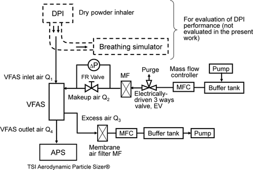
shows a measuring system with VFAS when it is applied to the evaluation of dispersion performance of the DPI with variable flow rates generated by a breathing simulator. The APS model 3321 can measure aerosol particles in the aerodynamic size range of 0.5–20 μm by the time-of-flight (TOF) principle. For the particles in this size range, particle loss due to gravitational settling and inertia is significant so that all connections from the sampling inlet to the inlet of the APS via VFAS are aligned straight and placed vertically.
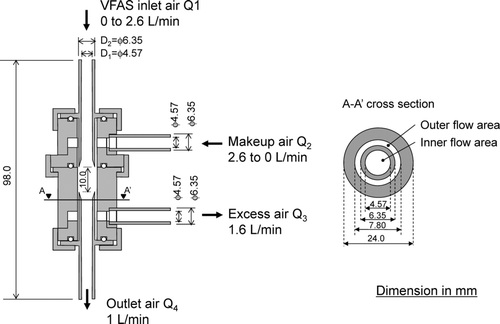
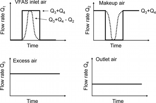
is a schematic diagram of VFAS. An outer flow area is essentially equal to an inner flow area at A-A′ cross section. The sampling flow rate of aerosol (Q 1) is controlled by varying the makeup airflow rate (Q 2) and the excess airflow rate (Q 3). When Q 2 is equal to Q 3, a vacuum pump equipped in the APS enables VFAS to withdraw air at the flow rate that is always equal to that of the APS (Q 4). The VFAS can produce any sampling flow rate and sampling flow pattern by adjusting Q 2 and Q 3 while keeping the flow rate to the APS, Q 4, constant. shows one example which produces constant sampling flow rate at the sampling nozzle (VFAS inlet) for a given period of time. In this figure, the flow rate of makeup air is initially set equal to the sum of excess air and the APS sampling air, i.e., Q 2 = Q 3 + Q 4. When the makeup airflow is turned off, the sampling flow rate (VFAS inlet) Q 1 rises to Q 3 + Q 4 and returns to zero when the makeup air is turned on. By changing the flow rate of Q 2, we may obtain the desired flow rate as Q 1 = Q 3 + Q 4 – Q 2.
The diameter of the VFAS aerosol-sampling inlet was determined by supposing its application to sample DPI-dispersed powder in human trachea. Generally, the human trachea has an inner diameter of ca. 20 mm (Phalen Citation1984). When the diameter of the VFAS inlet tube is 4.57 mm, the VFAS inlet flow rate, Q 1, should vary from 0 to 2.6 L/min for achieving isokinetic sampling at the VFAS inlet tube when the main flow rate varies from 0 to 50 L/min, i.e., the flow rate through DPI.
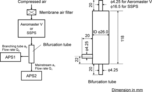
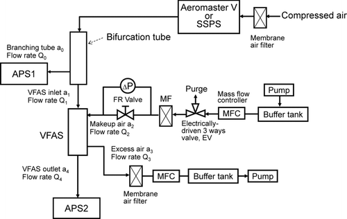
FIG. 4 Experimental setup for particle penetration measurements of the VFAS-APS system. Main flows of bifurcation tube, VFAS, and APS2 are connected straight and set vertical. See for dimensions of bifurcation tube.
The flow rates of VFAS, Q 1, Q 2, Q 3, and Q 4, were chosen in such a way that a fraction of makeup air, Q 2, is added to Q 1 to equal Q 4 when Q 1 < Q 4, while a fraction of Q 1 is discarded to equal Q 4 when Q 1 > Q 4. The discarded fraction of Q 1 did not exceed two-thirds of Q 1 at the maximum of Q 1 although it would be possible to design VFAS in which all the sampled air enters the APS at the maximum of Q 1. Furthermore, we designed the flow in VFAS to remain laminar even at the maximum of Q 1 + Q 2 and aligned the inlet flow and the outlet flow of VFAS straight for minimizing the particle deposition loss. When Q 1 + Q 2 in VFAS was maximum at 6 L/min, the Reynolds number was 1080, which ensured that laminar flow was present within the VFAS entry, and that turbulent mixing did not occur between the incoming flow containing the sampled aerosol and the makeup air.
VFAS Evaluation Procedure
Experimental setup for the determination of particle penetration through the VFAS-APS system is shown in . The particle concentration was measured by APS1 at the inlet to VFAS, and by APS2 at its outlet. The particle size-penetration profiles were measured by applying a rectangular flow rate pattern as shown in , where the flow rate at the VFAS inlet, Q 1, changes from zero to 2.6 L/min and lasts for 2 s when the makeup air is turned off (the makeup airflow rate: Q 2 = 2.6 L/min, the excess airflow rate: Q 3 = 1.6 L/min, and the inlet flow rate of the APS: Q 4 = 1 L/min).
The monodisperse particle standards used for the particle penetration test had the following properties: (i) certified mean diameters and its uncertainties of 0.707 ± 0.006 μm (catalog number 3700A), 0.993 ± 0.021 μm (4009A), and 1.998 ± 0.022 μm (4202A) (Duke Scientific Corporation, Palo Alto, CA, USA, NANOSPHERETM Size Standards, microsphere material: polystyrene); (ii) certified mean diameters and its uncertainties of 2.504 ± 0.025 μm (catalog number 4025A), 3.005 ± 0.027 μm (4203A), and 4.000 ± 0.033 μm (4204A) μm (Thermo Scientific, Fremont, CA, USA, Duke StandardsTM, Particle Size Standards, microsphere material: polystyrene); (iii) certified mean diameters and its uncertainties of 5.1 ± 0.4 μm (catalog number DC-05), 6.7 ± 0.4 μm (DC-07), 9.8 ± 0.5 μm (DC-10), and 15.8 ± 0.6 μm (DC-15) (Duke Scientific Corporation, Palo Alto, CA, USA, DRI-CALTM Particle Size Standards, microsphere material: polystyrene divinylbenzene). All of the particle standards used in our experiments were traceable to the National Institute of Standards Technology (NIST; in Gaithersburg, MD, USA).
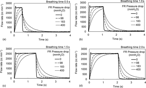
FIG. 6 Breathing flow rate patterns generated by changing the pressure drop of flow resistance of makeup air. The pressure drops shown are those measured at 1.05 L/min.
An AEROMASTER-V (JSR Corporation, Minato, Tokyo, Japan) was used to generate particles in the size range of 0.7–4 μm, and a Small-Scale Powder Disperser (SSPD) model 3433 (TSI Inc., Shoreview, MN, USA) for the size range of 5–15 μm. The AEROMASTER-V is recommended for the generation of particles with diameter as large as 2 μm according to the specification of the AEROMASTER-V. The AEROMASTER-V is composed of a nebulizer, a dilution tube with an electrical heater as dryer for atomized particles, and a neutralizer. In the present work, the dilution airflow rate of AEROMASTER-V was 18 L/min for generating particles in the size range of 0.7–1 μm, and 5 L/min for generation of particles in the size range of 2–4 μm. The heater temperature of the AEROMASTER-V was set at 80°C, and the atomization pressure at 0.18 MPa.
Prior to the measurement of particle penetration through VFAS, we investigated the influence of bifurcating aerosol flow on the aerosol concentrations and the difference in counting between two identical APS instruments (). The flow rates through the branching tube and the main tube were set equal to 1 L/min during this experiment.
A preliminary experiment was conducted to find the potential of VFAS for generating a desired flow pattern. The airflow rate–time profile, Q 1, was adjusted by changing the resistance of the makeup air because Q 1 varied very rapidly. The magnitude of this flow rate was determined using a rapid-response flow meter, i.e., spirometer (Fleisch pneumotachograph: type 00, i/a 7317, Dynasciences, a differential pressure transducer: model DP45–14, Validyne engineering Corp., Northridge, CA, USA, Pressure amplifier: PA501, KRONE Corp., Katsushika, Tokyo, Japan) by connecting it at the inlet of VFAS. For measuring steady flow rates, a film flow meter (SF-2U with VP-4 for 0.2–10 L/min and VP-2 for 0.002–0.1 L/min, HORIBA STEC Co. Ltd., Chiyoda, Tokyo, Japan) was employed.
RESULTS AND DISCUSSIONS
Generation of Variable Flow Patterns with VFAS
Examples of the airflow rate–time profiles of Q 1 generated with VFAS by changing the pressure drop of flow resistance (FR) valve (). The flow, Q 2, which was set at 2.6 L/min was turned off between 0.5 and 2 s by an electric valve, EV, while the flows Q 3 and Q 4 were kept constant at 1.6 L/min and 1 L/min, respectively. When the resistance of makeup air, FR valve, is zero, Q 1 shows a sharp rectangular change in flow rate. By increasing the flow resistance, the rectangular change in airflow rate–time profile loses its sharpness, and broadens. When the flow resistance was high, the pressure upstream of flow resistance was also high to produce the same mass flow rate. Consequently it took more time to ease the pressure to the atmospheric pressure, which caused the broadening in the airflow rate–time profile. When the flow, Q 2, was turned on, it took more time to build up the pressure upstream of flow resistance to attain constant flow rate of Q 2, which again caused the broadening in the airflow rate–time profile.
We observed that the broadened airflow rate–time profile is fairly close to the inhalation airflow rate–time patterns reported by Finlay and Gehmlich (Citation2000) and Lee et al. (Citation2004). It was surprising that such a simple flow system consisting of valves and flow resistance could generate this breathing pattern while producing a constant flow rate at the outlet of VFAS. We may generate an airflow rate–time pattern much closer to real inhalation pattern by adjusting the flow resistance and inserting a flow buffer for modifying the airflow rate–time profile.
Effect of Bifurcation on Particle Concentration and Difference in Counting of two APS
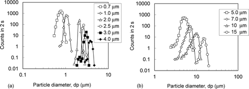
The particle size distributions of test particles generated by two types of particle generators were measured by APS () to check the monodispersity of these standards. The measured mean diameters, dp , are 0.75, 1.05, 2.09, 2.59, 3.00, 3.82, 5.15, 6.81, 9.49 and 15.01 μm, which are in good agreement with the certified mean diameters. The geometric standard deviations σg are 1.10, 1.07, 1.04, 1.04, 1.07, 1.08, 1.13, 1.12, 1.16 and 1.10, respectively. Since σg of particles generated by both AEROMASTER-V and SSPD were smaller than 1.2 (Hidy Citation1984; John Citation1993), it was concluded that the test particles were well-dispersed uniform-sized singlets.
FIG. 8 Particle counts of 1-μm particles at branching tube (a0) and main tube (a1) of bifurcation tube, and the ratio of these counts.
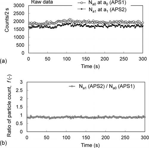
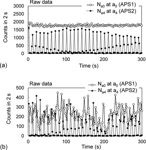
The counts for 1-μm particles for every 2 s were measured simultaneously by two APS at the branching tube (a0) and at the main tube (a1) (), and the ratios of these counts are shown in . The counts of 1-μm particles generated by AEROMASTER-V are constant over a period of 300 s, and the particle count of APS1 at the branching tube (a0) is 1935 ± 66 counts/2 s (CV 3.4%), and the particle count of APS2 at the main tube (a1) is 1705 ± 67 counts/2 s (CV 3.9%). Therefore, the ratio of particle counts is constant at 0.87 ± 0.03. A ratio smaller than unity may result from the difference in the calibration of these APS as well as anisoaxial sampling, and this phenomenon is discussed in more detail in the Discussion.
FIG. 9 Particle counts of 10-μm particles at branching tube (a0) and main tube (a1) of bifurcation tube, and the ratio of these counts.
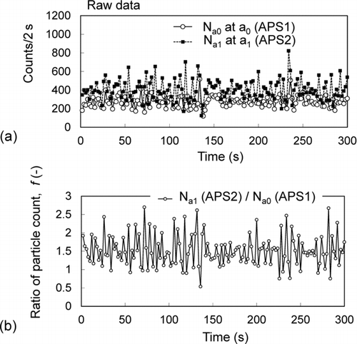
The count-elapsed time profiles at 2-s intervals for the 10-μm SSPD-generated particles are illustrated in . Although the fluctuation in particle count for 2 s is significant because of low concentration of 10-μm particles, the average concentration of 10-μm particles is quite constant for 300 s, which confirms the stable generation of particles by SSPD. The count rate measured by APS1 at the branching tube (a0) was 275 ± 59 counts/2 s (CV of 21%), whereas the count rate determined by APS2 at the main tube (a1) was 406 ± 111 counts/2 s (CV of 27%), so that the ratio between both measures, based on the ratio N a1/N a0, was close to 1.5. A count ratio N a1/N a0 greater than unity may be attributed to the lowered concentration of 10-μm particles in the branching tube (a0). The Reynolds number in the branching tube was estimated to be 108, and the corresponding Stokes number based on the branching tube diameter and mainstream flow velocity was 0.00476. According to Brockmann (Citation1993), in the case where a sampling tube is placed perpendicular to the main flow and the ratio of main flow velocity, U 0, to sampling flow velocity, U, is 0.5, anisoaxial sampling of aerosol may influence the sampled aerosol concentration when Stk exceeds 0.04. In the present experiments, the ratio, U 0/U, was 0.053, and the maximum Stk for 10-μm particles was 0.0048, and therefore the particle concentration in the branch tube (a0) would likely not have deviated significantly from that in the mainstream airflow. Consequently, the reduction in particle concentration in the branch tube (a0) is believed to have been caused by gravitational sedimentation, i.e., 10-μm particles cannot follow the stream lines of branching flow due to gravity so that less particles flow into the branching tube, resulting in a decrease in particle concentration.
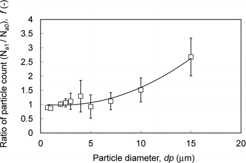
Figure 10 shows the ratio of particle counts, f = N a1/N a0, as a function of particle size, which is necessary to determine particle concentration at the VFAS inlet. This ratio is fairly constant, close to unity when the particle size is smaller than 7 μm, and increases with the particle size and reaches 2.5 at 15 μm.
Particle Detection Performance of VFAS-APS System
The performance of the VFAS-APS system was evaluated by generating a rectangular airflow rate–time profile at the VFAS inlet. shows the reading of APS1 at the branching tube (a0) together with the reading of APS2 at the outlet of VFAS (a4) at 2-s intervals. In the experiments, the flow rate pattern of aerosol at the VFAS inlet was one which corresponds to the flow rate pattern in without a flow constrictor, where Q 1 = 2.6 L/min, Q 3 = 1.6 L/min, Q 4 = 1 L/min, and Q 2 = 2.6 L/min were repeatedly turned on for 2 s and turned off for 8 s. In , which shows the particle count for 1-μm particles, the particle count at the inlet of VFAS (APS1 at a0) was constant at 1777 ± 50 counts/2 s, and the count at the outlet of VFAS was observed repeatedly to rise to a maximum and then return to zero within about 6 s because the test aerosol was introduced into VFAS for 2 s and shut off for 8 s. The corresponding APS-measured count rate-elapsed time profile for the 10-μm aerodynamic particles () had poor reproducibility for each on/off cycle for Q 2. This behavior was attributed to the fact that the particle concentration presented to the VFAS inlet was relatively low compared with that associated with the smaller particles, and fluctuated significantly.
FIG. 13 Particle penetrations of VFAS-APS. (a) Particle diameter 1 μm, and (b) 10 μm. These penetrations are corrected with f shown in .
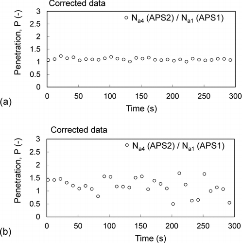
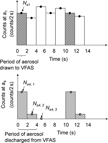
We estimated from the data in that the test aerosol introduced to VFAS for 2 s was discharged from the system within 6 s of entry. is an enlarged image of . As shown in , we calculated the penetrations through the VFAS for each cycle of turning on/off of Q 2 by the following equation:
We observed that the penetration of 1-μm aerodynamic diameter particles was close to the ideal value of unity (), suggesting that VFAS can measure the concentration of 1-μm particles without any deviation from the mainstream concentration, i.e., the concentration at the VFAS inlet. However, we noticed that the measured penetration of the larger 10-μm aerodynamic diameter particles per breath () fluctuated widely when the timing of the particle count at the inlet was not completely synchronized with that at the outlet. However, if the penetrations shown in are averaged over ten measurements, i.e., for 100 s, the average would remain almost constant. Note that the correction factor, f, used in the calculation of the penetration was the one shown in although the flow rates were different (Q 0 = Q 1 = 1 L/min for , and for , Q 1 = 2.6 L/min, Q 3 = 1.6 L/min, Q 4 = 1 L/min, and Q 2 = 2.6 L/min were repeatedly turned on and off).
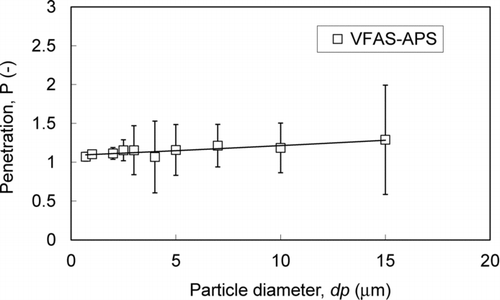
shows the particle penetration through VFAS as a function of particle aerodynamic size. The particle penetration is nearly equal to unity when the particle size is smaller than 4 μm and increases with the particle size. Penetrations larger than unity may be attributed to the larger flow rates at the bifurcation tube for obtaining (Q
0 = 1 L/min and Q
1 = 2.6 L/min) compared to the flow rates for (Q
0 = Q
1 = 1 L/min), i.e., the dependence of the correction factor on the particle size would be different from the one shown in . An increase in Q
1 would make more particles to follow the mainstream exiting at a1 because the residence time of particles in the branching tube would be shorter, so that the extent of the deviation of particles from the streamline due to gravity would be less pronounced, which would lead to an increase in both concentration at ![]() and the correction factor f.
and the correction factor f.
In consequence, if the correction factor f at Q 0 = 1 L/min and Q 1 = 2.6 L/min is determined, the particle penetration to VFAS would be close to unity, confirming that the VFAS-APS system is capable of measuring the particle number concentration in the size range of 0.5–15 μm aerodynamic diameter in a mainstream with variable flow rates.
CONCLUSIONS
An isokinetic measuring system for aerodynamic size of aerosol particles (VFAS) was designed and the performance was evaluated. Aerodynamic Particle sizer® APSTM spectrometer (TSI Inc, model 3321) with measurable size range of 0.5–20 μm was used for measuring the aerodynamic particle size. The major conclusions obtained by the present work are as follows:
| 1. | The VFAS is capable of generating variable sampling flow rates by adjusting the flow resistance of makeup air to produce constant flow rate of aerosol to APS. | ||||
| 2. | The penetrations through the VFAS-APS system for particles with the size range of 0.7–15 μm are close to unity for a rectangular flow rate pattern of sampling air. | ||||
In consequence, the VFAS-APS system may be a powerful tool to measure the size and concentration of powder dispersed by the DPI in the size range of 0.5–15 μm.
REFERENCES
- Brockmann , J. E. 1993 . “ Sampling and Transport of Aerosol ” . In Aerosol Measurement. Principles, Techniques, and Applications, , Edited by: Willeke , K. and Baron , P. A. 77 – 111 . New York : Van Nostrand Reinhold .
- Burnell , P. K. P. , Malton , A. , Reavill , K. and Ball , M. H. E. 1998 . Design, Validation and Initial Testing of the Electronic Lung™ Device . J. Aerosol Sci , 29 ( 8 ) : 1011 – 1025 .
- Chandra , S. and McFarland , A. R. 1997 . Shrouded Probe Performance: Variable Flow Operation and Effect of Free Stream Turbulence . Aerosol Sci. Technol. , 26 : 111 – 126 .
- Cheng , Y. S. , Yazzie , D. , Gao , J. , Muggli , D. , Etter , J. and Rosenthal , G. J. 2003 . Particle Characteristics and Lung Deposition Patterns in a Human Airway Replica of a Dry Powder Formulation of Polylactic Acid Produced Using Supercritical Fluid Technology . J. Aerosol Med. , 16 ( 1 ) : 65 – 73 .
- Chung , K. Y. K. and Ogden , T. L. 1986 . Some Entry Efficiencies of Disklike Samplers Facing the Wind . Aerosol Sci. Technol. , 5 : 81 – 91 .
- Delong , M. , Wright , J. , Dawson , M. , Meyer , T. , Sommerer , K. and Dunbar , C. 2005 . Dose Delivery Characteristics of the AIR® Pulmonary Delivery System Over a Range of Inspiratory Flow Rates . J. Aerosol Med. , 18 : 452 – 459 .
- Finlay , W. H. and Gehmlich , M. G. 2000 . Inertial Sizing of Aerosol Inhaled from Two Dry Powder Inhalers with Realistic Breath Patterns Versus Constant Flow Rates . Int. J. Pharm. , 210 : 83 – 95 .
- Gong , H. , Anand , N. K. and McFarland , A. R. 1993 . Numerical Prediction of the Performance of a Shrouded Probe Sampling in Turbulent Flow . Aerosol Sci. Technol. , 19 : 294 – 304 .
- Hidy , G. M. 1984 . Aerosols. An Industrial and Environmental Science. , 109 London : Academic Press .
- Irshad , H. , McFarland , A. R. and Landis , M. S. 2004 . Wind Tunnel Evaluation of an Aircraft-Borne Sampling System . Aerosol Sci. Technol. , 38 : 311 – 321 .
- Islam , N. and Gladki , E. 2008 . Dry powder inhalers (DPIs)—A review of device reliability and innovation . Int. J. Pharm. , 360 : 1 – 11 .
- John , W. 1993 . “ The Characteristics of Environmental and Laboratory-Generated Aerosols ” . In Aerosol Measurement. Principles, Techniques, and Applications, , Edited by: Willeke , K. and Baron , P. A. 54 – 76 . New York : Van Nostrand Reinhold .
- Lee , S.-G. , Nashimoto , M. , Otani , Y. , Ishizeki , K. and Oki , H. 2004 . Dispersion of Drug Particles by Dry Powder Inhaler under Simulated Condition of Inhalation Pattern . J. Soc. Powder Technol. Japan , 41 : 500 – 507 .
- Mitchell , J. P. and Nagel , M. W. 1999 . Time-of-Flight Aerodynamic Particle Size Analyzers: Their Use and Limitations for the Evaluation of Medical Aerosols . J. Aerosol Med. , 12 ( 4 ) : 217 – 240 .
- Nantel , N. P. and Newhouse , M. T. 1999 . Inspiratory Flow Rates Through a Novel Dry Powder Inhaler (Clickhaler) in Pédiatrie Patients with Asthma . J. Aerosol Med. , 12 ( 2 ) : 55 – 58 .
- Phalen , P. F. 1984 . Inhalation Studies: Foundations and Techniques. , 230 Boca Raton , FL : CRC Press .
- Ragab , D. , Rohani , S. , Samaha , M. W. , El-Khawas , F. M. and El-Maradny , H. A. 2010 . Crystallization of Progesterone for Pulmonary Drug Delivery . J. Pharm. Sci., , 99 ( 3 ) : 1123 – 1137 .
- Tiddens , H. A. , Geller , D. E. , Challoner , P. , Speirs , R. J. , Kesser , K. C. Overbeek , S. E. 2006 . Effect of Dry Powder Inhaler Resistance on the Inspiratory Flow Rates and Volumes of Cystic Fibrosis Patients of Six Years and Older . J. Aerosol Med., , 19 ( 4 ) : 456 – 465 .
- Twohy , C. H. 1998 . Model Calculations and Wind Tunnel Testing of an Isokinetic Shroud for High-Speed Sampling . Aerosol Sci. Technol., , 29 : 261 – 280 .
- von Berg , A , Kremer , H.-J. , Ellers-Lenz , B. , Conrad , F. , Erb , K. , Maus , J. and Hermann , R. 2007 . Peak Inspiratory Flow Rates Generated Through the Novolizer® and the Turbuhaler® Dry Powder Inhaler Devices by Children with Stable Asthma . J. Aerosol Med., , 20 ( 1 ) : 50 – 58 .
