Abstract
Transport and deposition of solid particles in a differentially heated cavity at high Rayleigh numbers up to 108 was studied using an Eulerian–Lagrangian computational method. Two-dimensional Navier-Stokes and energy equations were solved and the motions of particles with diameters in the range of 10 nm to 10 μm were simulated. Effects of drag, lift, thermophoresis and Brownian forces on the particle trajectories were investigated. It was observed that the variation of Rayleigh number can significantly change the flow field and the corresponding particle deposition patterns. In particular, recirculation regions were formed near the corners as the Rayleigh number increased. Furthermore, the effects of changes in the Rayleigh numbers on transport and deposition of particles of different sizes were quite different. Increasing Rayleigh number from 107 to 108 caused a decrease in particles deposition except for 10 μm particles. Smaller particles had a higher probability to deposit on the cold wall as the thermophoresis effect becomes important. Increasing the Rayleigh number decreased the influencing zone of the thermophoresis in the vicinity of the walls.
Copyright 2012 American Association for Aerosol Research
1. INTRODUCTION
Concentration of particulate matter (PM) in indoor air is an important air quality issue (Wallace Citation1996). Numerous studies have reported the effects of inhaling particulate matters on human health such as lead poisoning (Thatcher et al. Citation1996), allergic reactions (Roberts et al. Citation1992) and cardiopulmonary diseases (Pope Citation2000). In addition to serious medical concerns, particle contamination in air could be damaging to museum art collections and soiling of historical monuments exposed to atmosphere (Baer and Banks Citation1985; Nazaroff and Cass Citation1991; Hamilton and Mansfield Citation1992). Particulate micro-contamination has been of serious concern in integrated circuits manufacturing in microelectronic industries (Cooper Citation1986; Bae et al. Citation1994; Weschler et al. Citation1996).
In order to improve indoor air quality, a detailed understanding of the particle behavior in indoor environments is needed. An important aspect of airflow in indoor environments is the formation of circulation due to the natural convection around heated bodies. The magnitude of the temperature gradients formed controls the intensity of these circulations, which significantly affects the transport of particle of different sizes.
Natural convection in enclosures has been the subject of numerous studies. Most of the earlier works can be classified in three main groups, namely, cavities where the flow is due to internal heat generation, cavities heated from below (Rayleigh–Benard configuration), and those heated from the sides (differentially heated cavity) (Thatcher et al. Citation1996; Trias et al. Citation2007, Citation2010a,Citationb; Puragliesi et al. Citation2011). These earlier works have shown, despite the simplicity of cavity geometry, the resulting convective flows and the temperature fields could become quite complex. For Rayleigh numbers less than 106, the flow is laminar, the transition occurs for 106 < Ra < 108, and the flow becomes fully turbulent for Rayleigh numbers larger than1.831×108. Computer simulations of laminar and turbulent natural convections in the differentially heated cavity were reported in (de Vahl Davis and Jones Citation1983; de Vahl Davis Citation1983; Hortmann et al. Citation1990; Le Quéré Citation1991; Dixit and Babu Citation2006; Trias et al. Citation2007, 2009, Citation2010; Puragliesi et al. Citation2011).
Le Quéré (Citation1991) suggested that the two-dimensional numerical simulation of a differentially heated cavity at high Rayleigh numbers may not lead to a physically correct solution. Thatcher et al. (Citation1996) investigated particle deposition mechanism in a closed cavity experimentally. Their cavity had two cold walls (the top and the left walls) and two heated walls (the bottom and the right walls). They studied different particle diameters in the range of 0.1 to 2.5 μm in flows with high Rayleigh numbers in the range of 6 × 10⁸ to 4 × 10⁹. For particles with diameters larger than 0.1 μm they found that the largest deposition rate occurred on the bottom wall due to the gravitational settling. Also they showed that deposition on the cold wall for 0.1 μm particles was at least 3.5 orders of magnitude larger than that on the hot wall. However, for 2.5 μm particles the depositions rate on the cold and hot walls were roughly the same since the thermophoretic effects become quite weak for larger particles. Yarin et al. (Citation1996) studied capability of using non-buoyant particles as tracer inside a differentially heated cavity experimentally and numerically for Ra = 105 and Pr = 1100. The tracer particles had non-spherical shapes with mean diameter of 350 μm. They found that the particles can be trapped in convective recirculation region of the flow while the other parts of the flow are particle-free. Trias et al. (Citation2007), however, performed a series of two- and three-dimensional simulations of a differentially heated air-filled cavity with an aspect ratio of 4 with adiabatic horizontal walls. Their results showed that the differences between two- and three-dimensional simulations become significant only for Rayleigh numbers higher than 6.4 × 10⁸ for which the flow is fully turbulent. Thus, for transitional flows, a two-dimensional simulation is appropriate. Zhang and Chen (Citation2009) proposed an anisotropic particle–eddy interaction model for the Lagrangian method to predict the particle deposition process in a cavity similar to Thatcher et al. (Citation1996) for Ra = 4 × 10⁹. They focused on the performance of v2-f turbulence model and made comparison with the experimental data and DNS results.
Akbar et al. (Citation2009) also performed a numerical study of particle motions in a differentially heated cavity. They investigated transport mechanism of 50 nm to 1 μm particles in laminar flow regimes with the Rayleigh number in the range of 102 to 8 × 10⁵. Trias et al. (Citation2010a,b) investigated the heat transfer and flow dynamics of a differentially heated cavity of aspect ratio 4 for Rayleigh numbers up to 1011 by Direct Numerical Simulation. Puragliesi (Citation2010) numerically investigated the deposition process of particles of the order of 10 micron in two- and three-dimensional cavities at a high Rayleigh number of Ra = 109. He found that the effect of third velocity component on the deposition process is negligible and the settling process is basically two dimensional. In the most recent work, Puragliesi et al. (Citation2011) investigated a two dimensional direct numerical simulation of particle transport in a heated cavity at high Rayleigh numbers of Ra = 109 and 1010. They tracked particles with diameters of 15, 25, 35 μm in a square cavity filled with air. They found that particles with diameters larger than 10 μm deposited preferentially on the bottom wall and the effect of thermophoretic force were negligible under the condition of their simulations. The particles tracked in their work were in the size range that the thermophoretic force does not noticeably affect the particle motion. Although there was a potential for particle deposition on the cold wall for the small particles due to the thermophoresis force, they did not investigate the deposition of small particles. To the best of authors knowledge, there is no publication reporting the experimental or numerical study of particle transport and deposition in the size range of 10 nm to 10 μm in differentially heated cavities for the range of 106 < Ra < 108.
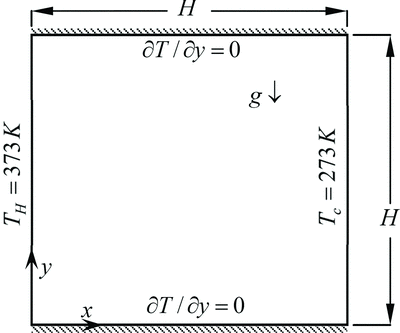
In the present study, a differentially heated cavity filled with air is modeled at different Rayleigh numbers between 105 and 108 by solving the two-dimensional steady state coupled Navier-Stokes and energy equations. Xin and Le Quéré (Citation2006) reported that flows in heated cavities with aspect ratio of 1 are steady and stable as long as the Rayleigh number is less than 1.831 × 10⁸. This Rayleigh number is called critical Rayleigh number. The configuration of the cavity is shown in with the hot wall temperature of Th and the cold wall temperature of Tc . The horizontal upper and lower walls are assumed to be adiabatic. Air is heated along the hot wall and rises, while the cooled air falls along the cold wall. Both laminar and transitional flow regimes are analyzed. For high Rayleigh numbers, a high resolution grid was used to capture the features of the unsteady transitional flows in the cavity. Particles with diameters in the range of 10 nm to 10 μm are studied for each Rayleigh numbers. Effects of drag, lift, thermophoresis and Brownian motion are included in the particle equation of motion. Particles are initially distributed randomly with a uniform distribution and with zero velocities. Effects of temperature gradient and the airflow fields on the particles transport and deposition are studied, and the effects of Rayleigh numbers and particle diameters are analyzed. In particular, the effects of corner vortices, which become larger by increasing the Rayleigh number, on the particle deposition are discussed in detail.
2. MATHEMATICAL MODEL
2.1. Fluid and Thermal Field
In this study, the continuous phase was simulated by solving the coupled continuity, Navier-Stokes and energy equations. Since the maximum Rayleigh number simulated in this study is less than critical Rayleigh number (Xin and Le Quéré Citation2006), the time dependency is ignored and the governing equations for a steady two-dimensional flow and thermal field are used in these simulations:
The corresponding boundary conditions are:
2.2. Particle Trajectory Analysis
The Lagrangian particle equation of motion is given as (He and Ahmadi Citation1998):
The fourth term on the right hand side of EquationEquation (9) is shear induced lift force. Particles in a shear field experience a lift force perpendicular to the direction of the flow. The lift force is modeled based on Li and Ahmadi (Citation1992) that is a generalization of the expression provided by Saffman (Citation1965):
FIG. 2Time variation of fraction of particles of different sizes remaining suspended in the cavity for different Rayleigh numbers.
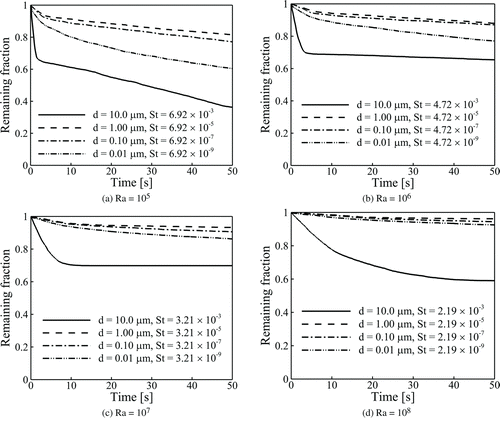
FIG. 4Particle deposition for different Rayleigh numbers and particle diameters: (a) bottom wall; (b) cold wall.
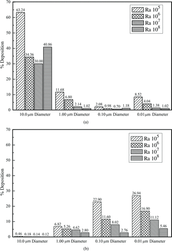
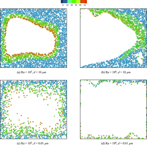
FIG. 5Initial position of deposited particles in the cavity. 10 μm particles deposited on the bottom wall for (a) Ra = 105 and (b) Ra = 108; 0.01 μm particles deposited on the cold (right) wall for (c) Ra = 105 and (d) Ra = 108. Color indicates the deposition time in seconds. (Color figure available online.)
3. NUMERICAL PROCEDURE
A computer code, written in FORTRAN language, was developed and used to solve the governing equations of the fluid flow and thermal field, as well as particle trajectory analysis. The code has two main parts—the first part is the solver for Eulerian analysis of flow and thermal fields and the second part is for Lagrangian particle tracking. The Eulerian solver is an improved version of the program described by Bagheri et al. (Citation2010). The free convection inside the cavity is modeled via the Boussinesq approximation, which implies that the variation of fluid density with temperature is negligible except in the source term of y-momentum EquationEquation (3), ρgβ(T − T0). Additional details of the computational model are available in Part A as online Supplemental Information. When converged solutions for the flow field and thermal conditions are obtained, the simulation results are used for the Lagrangian particle trajectory analysis. In order to find the proper value of the integration time-step for solving particle equation of motion and the total number of injected particles, various independency tests were performed for extreme Rayleigh numbers and particle sizes. Integration time steps between 10−3 and 10−7 s were used in the tests. It was found that the time step for larger than10 and 1 μm particles should be of the order of 10−4 s or smaller (based on their relaxation time). For Brownian particles of the order of 0.1 and 0.01 μm a time step of the order of 10−5 s is appropriate. While this time step is larger than the relaxation time of the nano-particles, it is still acceptable as the inertia of these particles is negligible. Ensembles of 2000 to 20,000 particles were tested and found no significant changes in the results from those for 5000 particles. Therefore, ensembles of 5000 particles with random initial positions and zero initial velocities were tracked over 50 s for different particle diameters.
4. RESULTS AND DISCUSSION
The fluid in the cavity is air and its effective properties at temperature of 323 K are used. In all simulations the particles are assumed to have a density of 2220 [kg m−3] and thermal conductivity of 1.38 Wm−1K−1. Size range of 10 nm to 10 μm particles has been tested. Particle Stokes number (![]() ) is varying between 2.2 ×10⁻⁹ and 6.9 × 10⁻³.
) is varying between 2.2 ×10⁻⁹ and 6.9 × 10⁻³.
A series of benchmark cases are studied by our code to ensure the validity of the results on fluid and temperature fields and Lagrangian particle tracking. The validation results are available in Part B as online supplemental information.
For different Rayleigh numbers, the cavity dimension is evaluated from the following equation:
also shows that, as the particle diameter decreases from 1 μm to 0.01 μm, the fraction of particles that remain suspended decreases. This is because for ultra-fine particles the intensity of Brownian motion increases as the particle size becomes smaller. The increase in Brownian diffusion increases the particle deposition rate.
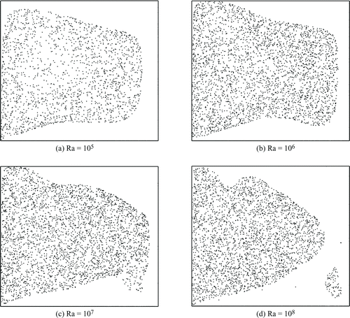
The effects of Rayleigh number on the particle deposition could also be seen in . As the Rayleigh number increases, the fraction of suspended particles increases for all diameters. The exception is for the 10 μm particles for the Rayleigh number of 108 for which the fraction of suspended particle decreases. To understand the reasons for this behavior, spatial distributions of 10 μm particles after 50 s of tracking are shown in . As noted earlier, these particles were initially uniformly distributed. Particles near the bottom wall deposit quickly as gravity moves the 10 μm particles downward. Similarly, particles near the top wall move down towards the center circulations and the top region becomes clear of particles. As the flow stream near the cold wall is downward, the superposition of the gravity and inertia causes the particles near the cold surface to fall towards the bottom wall. Near the hot wall, however, the airflow stream is upward and carries the particles upward despite the opposing gravity. The circulation also moves the bulk of 10 μm particles toward the hot wall as thermophoresis is not strong for these relatively large particles. In the lower part of the hot wall, where the upward circulating flow is rather weak, however, the 10 μm particles fall and deposit. Circulation in the cavity becomes stronger with increasing Rayleigh number; thus, more particles are captured by the circulating flow and stay away from the wall that decreases their deposition chance. This particle trapping in the core circulation region is similar to that observed by Yarin et al. (Citation1996), although their experiment was for different conditions compared to those used in the present simulations. For Rayleigh number of 108, however, the corner vortices also become quite strong and penetrate into the core circulation that cause higher particle deposition compared to the Rayleigh numbers of 106 and 107. Growth of corner vortices captures more particles from the center region and brings the particles near the wall region that increases the deposition chance. It is worth mentioning that, although there is higher particle deposition near the corner vortices for Ra = 107compared to the case for Ra = 106, the total deposition of 10 μm for Rayleigh number of 107 is lower than the case for Ra = 106 because the core circulation is stronger in case of Ra = 107.
Spatial distributions of 0.01, 0.1, and 1.0 μm particles after 50 s of tracking have also been investigated. The simulation results showed that the spatial distributions for other particle sizes after 50 s are almost similar together and particles keep their relatively initial uniform distributions. This is because the particle inertia and gravity effects are not important.
shows the contributions of the bottom (horizontal) and cold (right vertical) walls on particle deposition for different Rayleigh numbers and particle diameters. For all Rayleigh numbers, shows that the deposition on the bottom wall for 10 μm particles is significantly higher than the other diameters. This is due to the gravitational sedimentation effect that increases the deposition rate of the large particles. This is in agreement with the findings of Puragliesi et al. (Citation2011) who reported that the particles with diameters larger than 10 μm mostly deposited on the bottom wall of the heated cavity.
Particle deposition on the cold wall is shown on . It is seen that as the particle size decreases the deposition on the cold wall increases and the deposition rate of 10 μm particles is the lowest. This is due to the combined effect of Brownian motion and thermophoretic effect that move the particles toward the cold wall. On the other hand, for a fixed particle diameter, deposition rate is higher in lower Rayleigh numbers. The reason is that the thermal boundary layer becomes thinner as the Rayleigh number increases and, since the magnitude of the thermophoretic force is related to temperature gradient, thinning of temperature boundary layer reduces the region and the thermophoresis effects become important. As a result, the thinning of thermophoresis effecting zone decreases the chance of particle deposition on the cold wall.
For better understanding of the deposition process, initial position of the deposited particles in extreme sizes of 10 μm and 0.01 μm and Rayleigh numbers of 105 and 108 are plotted in . show the initial position of 10 μm particles, which are deposited on the bottom wall, respectively, for Ra = 105 and 108. Only the deposition on the bottom wall is plotted for 10 μm particles, because most of these particles are deposited on this wall (). It can be seen form these figures that particles near top, bottom, and cold walls deposit on the bottom wall in less than 10 s. For Ra = 105, even particles near hot wall are deposited on the bottom wall after they are transported by the circulating core flow near the left-bottom corner. The exception is for the case of Ra = 108 because the circulation is quite strong and the particles cannot escape the circulating region. For Ra = 108, however, a second phase of deposition occurs when the particles in the outer ring of the core circulation region reach to the corner circulation and deposit on the bottom wall.
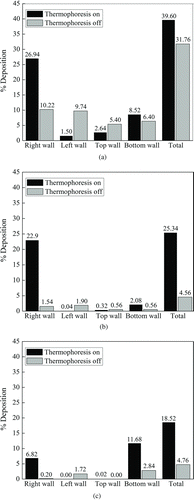
FIG. 6 Particle deposition on different walls in the absence and presence of thermophoresis for Ra = 105 after 50 s of tracking for particle diameters of: (a) 0.01 μm, (b) 0.1 μm, (c) 1 μm.
Similarly, show that the initial position of 0.01 μm particles on the cold wall, respectively, for Ra = 105 and 108. Since the majority of deposition for these ultra-fine particles occurs on the cold wall (), only the deposition on this wall is plotted. shows the effect of Brownian motion that result in escaping of 0.01 μm particles even from the middle of the core circulation region in low Rayleigh numbers. This figure also shows that particles with initial position near any of the cavity walls have the chance for depositing. The chance for deposition, however, is higher for the particles initially released near the top or the bottom walls. shows that for Rayleigh number of 108, unlike Rayleigh of 105, 0.01 μm particles cannot escape from the high intensity core circulation region and deposit on the walls.
Thermophoresis effects generally become stronger as particle diameter decreases. displays the effect of thermophoresis on the deposition of 0.01, 0.1, and 1 μm particles on different surfaces of the cavity by comparing the deposition on different walls in the absence and presence of thermophoresis in the simulations for Rayleigh number of 105. It is observed that the maximum deposition of particles for Rayleigh number of 105 on the right cold wall occurs for 0.01 μm particles. However, the maximum effect of the presence of thermophoresis shows itself for 0.1 μm particles. When thermophoresis is considered in the analysis, the total deposition rate of 0.1 μm particles is more than 5.5 times than that when the thermophoresis is neglected. This ratio for 1 and 0.01 μm particles are, respectively, 3.9 and 1.2 times. It is seen that when the thermophoresis is on, the deposition on the right cold wall and the bottom wall increases and the trend is reverse for the other two walls. Because the temperature decreases with the distance from the left and top walls, the thermophoresis force direction is away from these walls and tend to move the particles away and thus decreasing their deposition rates. Additional results about the vectors and counters of thermophoretic force and its effects on the particle deposition are available in Part C as online Supplemental Information.
Previous simulations by Marchioli et al. (Citation2007) for particle transport in a turbulent vertical channel flow showed that the lift force is the major mechanism that can increase the deposition of particles on the cold wall and decrease deposition on the hot wall. They found that this effect is more pronounced for particles with the Stokes numbers in the range of 0.2 to 5. In order to examine the effect of lift force on the deposition of particles in the present heated cavity on particles with Stokes numbers much less than 0.2 studied by Marchioli et al. (Citation2007), some simulations were performed by neglecting this force and the results are compared with the case that the lift force is present. The results showed that no difference is observed when the lift force is considered or neglected. That is the lift force is not important for the Stokes numbers less than 0.2 studied in the present case.
5. CONCLUSIONS
The particles' behavior in a deferentially heated cavity was studied numerically. Both laminar and transitional regimes were considered and the Navier-Stokes and continuity was used for fluid flow simulation in the two-dimensional cavity. The computational model for analyzing fluid flow and particle trajectories were validated by comparison with the earlier published numerical studies in the literature. Ensembles of 5000 solid particles with diameters of 0.01, 0.1, 1, and 10 μm were tracked for up to 50 s from their random initial distributions. Gravity, thermophoresis, Brownian, and lift and drag forces are included in the particle equation of motion. Particular attention was given to the effects of Rayleigh number, gravity, thermophoresis, and particle diameter on the deposition of particles. On the basis of the presented results, the following conclusions are drawn:
| • | Increasing the Rayleigh number decreased the deposition rate of small particles for which the gravitational sedimentation is not important. | ||||
| • | Increasing Rayleigh number from 107 to 108 increased the deposition of 10 μm particles on the bottom wall. This is because of formation of corner circulations region and weakening the main central circulation. | ||||
| • | Thermophoresis increases the particle deposition on the vertical cold wall as the particle diameter decreases. | ||||
| • | Particles in the range of 1 μm to 0.1 μm have low deposition rate as they typically follow the flow streamlines. The thermophoresis and Brownian effects, however, increase the deposition of these particles. | ||||
| • | Thinning of thermal boundary layer at high Rayleigh numbers reduces the deposition rate of small particles due to the reduction of the region that thermophoresis force becomes important. | ||||
| • | Thermophoresis could be used for the removal of the particle from a warm gas stream by increasing the deposition of small particles on cold walls. | ||||
| • | Effect of lift force on the deposition of particles in all cases (d < 10 μm and St < 0.219) is negligible. | ||||
NOMENCLATURE
| Cc | = |
Cunningham's factor |
| CD | = |
Drag coefficient |
| Cm | = |
Constant in EquationEquation (17) (= 1.14) |
| cp | = |
Fluid specific heat |
| Cs | = |
Constant in EquationEquation (17) (= 1.17) |
| Ct | = |
Constant in EquationEquation (17) (= 2.18) |
| d | = |
Particle diameter |
| dij | = |
Deformation tensor =(u i,j +u j,i )/2 |
| F L,i | = |
Lift force in the i direction |
| F Th,i | = |
Thermophoretic force in the i direction |
| g | = |
Gravity acceleration |
| Gi | = |
Gaussian random numbers |
| H | = |
Cavity dimension (height and width) |
| K | = |
Constant in EquationEquation (15) (= 2.594) |
| kB | = |
Boltzmann constant (=1.38×10⁻²³) |
| K | = |
Fluid thermal conductivity |
| kP | = |
Particle thermal conductivity |
| Kn | = |
Knudsen number (=2λ/d) |
| N | = |
Number of particles |
| ni (t) | = |
Brownian force |
| p | = |
Fluid pressure |
|
| = |
Prandtl number (=cp μ/k) |
| R | = |
Universal gas constant |
| Ra | = |
Rayleigh number ( |
|
| = |
Relative Reynolds number (=ρd|up −u|/μ) |
| S | = |
Relative density (=ρ p /ρ) |
| St | = |
Stokes number ( |
| T | = |
Fluid temperature |
| T 0 | = |
Reference temperature (=(Th +Tc )/2) |
| T | = |
time |
| u | = |
Fluid velocity in the x direction |
| ui | = |
Fluid velocity in the i direction |
| u i,j | = |
∂ui /∂xj |
| u P,i | = |
Particle velocity in the i direction |
| v | = |
Fluid velocity in the y direction |
| x | = |
Horizontal direction of Cartesian coordinates (see ) |
| y | = |
Vertical direction of Cartesian coordinates (see ) |
Greek Symbols
| ρ | = |
Fluid density |
| ρ P | = |
Particle density |
| β | = |
Thermal expansion coefficient |
| λ | = |
Mean free path of the fluid |
| μ | = |
Dynamic viscosity |
| υ | = |
Kinematic viscosity |
| τ | = |
Particle relaxation time (EquationEquation (12)) |
| α | = |
Thermal diffusivity |
| Δ | = |
Gradient |
Subscripts
| c | = |
Cold |
| H | = |
Hot |
| i | = |
Vector axis indicators |
| L | = |
Lift |
| p | = |
Particle |
|
| = |
Thermophoresis |
| x, y | = |
Axis indicators |
uast_a_716550_sup_27885566.zip
Download Zip (3.9 MB)Acknowledgments
[Supplementary materials are available for this article. Go to the publisher's online edition of Aerosol Science and Technology to view the free supplementary files.]
REFERENCES
- Akbar , M. K. , Rahman , M. and Ghiaasiaan , S. M. 2009 . Particle Transport in a Small Square Enclosure in Laminar Natural Convection . J. Aerosol Sci. , 40 : 747 – 761 .
- Baer , N. S. and Banks , P. N. 1985 . Indoor Air Pollution: Effects on Cultural and Historic Materials . Int. J. mus. manage. Curatorship. , 4 : 9 – 20 .
- Bae , G. N. , Lee , C. S. and Park , S. O. 1994 . Measurement of Particle Deposition Velocity Toward a Horizontal Semiconductor Wafer by Using a Wafer Surface Scanner . Aerosol Sci. Technol. , 21 : 72 – 82 .
- Bagheri , G. H. , Mehrabian , M. A. and Hooman , K. 2010 . Numerical Study of the Transient Behaviour of a Thermal Storage Module Containing Phase-Change Material . Proc. Inst. Mech. Eng., A, J. Power Energy , 224 ( 4 ) : 505 – 516 .
- Cooper , D. W. 1986 . Particulate Contamination and Microelectronics Manufacturing: An Introduction . Aerosol Sci. Technol. , 5 : 287 – 299 .
- deVahl , D. G. 1983 . Natural Convection of Air in a Square Cavity: A Benchmark Numerical Solution . Int. J. Numer. Meth. Fluids , 3 ( 3 ) : 249 – 264 .
- deVahl , D. G. and Jones , I. P. 1983 . Natural Convection in a Square Cavity: A Comparison Exercise . Int. J. Numer. Meth. Fluids , 3 ( 3 ) : 227 – 248 .
- Dixit , H. N. and Babu , V. 2006 . Simulation of High Rayleigh Number Natural Convection in a Square Cavity Using the Lattice Boltzmann Method . Int. J. Heat Mass Transf. , 49 : 727 – 739 .
- Hamilton , R. S. and Mansfield , T. A. 1992 . The Soiling of Materials in the Ambient Atmosphere . Atmos. Environ. , 26 : 3291 – 3296 .
- He , C. and Ahmadi , G. 1998 . Particle Deposition with Thermophoresis in Laminar and Turbulent Flows . Aerosol Sci. Technol. , 29 : 525 – 546 .
- Hortmann , M. , Peric , M. and Scheuerer , G. 1990 . Finite Volume Multigrid Prediction of Laminar Natural Convection: Bench-mark Solutions . Int. J. Numer. Meth. Fluids , 11 ( 2 ) : 189 – 207 .
- Le Quéré , P. 1991 . Accurate Solutions to the Square Thermally Driven Cavity at High Rayleigh Number . Comput. Fluids , 20 : 29 – 41 .
- Li , A. and Ahmadi , G. 1992 . Dispersion and Deposition of Spherical Particles from Point Sources in Turbulent Channel Flow . Aerosol Sci. Technol. , 16 : 209 – 226 .
- Marchioli , C. , Picciotto , M. and Soldati , A. 2007 . Influence of Gravity and Lift on Particle Velocity Statistics and Transfer Rates in Turbulent Vertical Channel Flow . Int. J. Multiphase Flow , 33 : 227 – 251 .
- Nazaroff , W. W. and Cass , G. R. 1991 . Protecting Museum Collections from Soiling Due to the Deposition of Airborne Particles . Atmos. Environ. , 25 : 841 – 852 .
- Pope , C. A. III. 2000 . Review: Epidemiological Basis for Particulate Air Pollution Health Standards . Aerosol Sci. Technol. , 32 : 4 – 14 .
- Puragliesi , R. 2010 . Numerical Investigation of Particle-Laden Thermally Driven Turbulent Flows in Enclosure , Lausanne, Switzerland : École Polytechnique Fédérale de Lausanne . Ph.D. thesis, No. 4600
- Puragliesi , R. , Dehbi , A. , Leriche , E. , Soldati , A. and Deville , M. O. 2011 . DNS of Buoyancy-Driven Flows and Lagrangian Particle Tracking in a Square Cavity at High Rayleigh Numbers . Int. J. Heat Fluid Flow , 32 : 915 – 931 .
- Roberts , J. W. , Budd , W. T. , Ruby , M. G. , Camann , D. E. , Fortmann , R. C. Lewis , R. G. 1992 . Human Exposure to Pollutants in the Floor Dust of Homes and Offices . J. Exposure Anal. Environ. Epidemiol. , 1 : 127 – 146 .
- Saffman , P. G. 1965 . The Lift on a Small Sphere in a Slow Shear Flow . J. Fluid Mech. , 22 : 385 – 400 .
- Talbot , L. , Cheng , R. K. , Schefer , R. W. and Willis , D. R. 1980 . Thermophoresis of Particles in a Heated Boundary Layer . J. Fluid Mech. , 101 : 737 – 758 .
- Thatcher , T. L. , Fairchild , W. A. and Nazaroff , W. W. 1996 . Particle Deposition from Natural Convection Enclosure Flow onto Smooth Surfaces . Aerosol Sci. Technol. , 25 : 359 – 374 .
- Trias , F. X. , Gorobets , A. , Soria , M. and Oliva , A. 2010a . Direct Numerical Simulation of a Differentially Heated Cavity of Aspect Ratio 4 with Rayleigh Numbers up to 1011 – Part I: Numerical Methods and Time-Averaged Flow . Int. J. Heat Mass Tran. , 53 : 665 – 673 .
- Trias , F. X. , Gorobets , A. , Soria , M. and Oliva , A. 2010b . Direct Numerical Simulation of a Differentially Heated Cavity of Aspect Ratio 4 with Rayleigh Numbers up to 1011– Part II: Heat Transfer and Flow Dynamics. . Int. J. Heat and Mass Tran. , 53 : 674 – 683 .
- Trias , F. X. , Soria , M. , Oliva , A. and Pérez-Segarra , C. D. 2007 . Direct Numerical Simulations of Two- and Three-Dimensional Turbulent Natural Convection Flows in a Differentially Heated Cavity of Aspect Ratio 4 . J. Fluid Mech. , 586 : 259 – 293 .
- Wallace , L. 1996 . Indoor Particles: A Review . J. Air Waste Manage. Assoc. , 46 : 98 – 126 .
- Weschler , C. J. , Shields , H. C. and Shah , B. M. 1996 . Understanding and Reducing the Indoor Concentration of Submicron Particles at a Commercial Building in Southern California . J. Air Waste Manage. Assoc. , 46 : 291 – 299 .
- Xin , S. and Le Quéré , P. 2006 . Natural-Convection Flows in Air-Filled, Differentially Heated Cavities with Adiabatic Horizontal Walls . Numer. Heat Tr. A-Appl. , 50 : 437 – 466 .
- Yarin , A. L. , Kowalewski , T. A. , Hiller , W. J. and Koch , S. 1996 . Distribution of Particles Suspended in Convective Flow in Differentially Heated Cavity . Phys. Fluids , 8 : 1130 – 1140 .
- Zhang , Z. and Chen , Q. 2009 . Prediction of Particle Deposition onto Indoor Surfaces by CFD with a Modified Lagrangian Method . Atmos. Environ. , 43 : 319 – 328 .
