Abstract
We report the design of a small optical particle counter with high sensitivity and low construction cost for atmospheric aerosol measurements. Particle sensing is based on the detection of the forward scattering of laser light. The separation of the laser beam and scattered light is achieved with a novel yet simple optical system. A laboratory prototype system with a 405-nm laser and photomultiplier tube detector has successfully detected polystyrene latex particles as small as 125 nm in diameter with unit efficiency. Theoretical calculations suggest that a lower detectable size limit of 100 nm can be achieved with reduction of background scattered light. The new counter will be useful in a variety of ground-based as well as small balloon-borne applications such as vertical profiling and in situ measurement of particles from explosive volcanic eruptions.
Copyright 2013 American Association for Aerosol Research
INTRODUCTION
Atmospheric aerosol plays an important role in Earth's climate (Haywood and Boucher Citation2000; IPCC Citation2007). Aerosol scatters sunlight, thus directly exerting a negative radiative forcing on climate (Anderson et al. Citation2003). A fraction of aerosol mass absorbs sunlight and causes a positive direct radiative forcing (Chung et al. Citation2010). Indirectly, aerosol affects cloud formation and evolution, leading to changes of cloud albedo, lifetime, and rainfall (Twomey Citation1974; Albrecht Citation1989; Pincus and Baker Citation1994). At ground level, high aerosol loadings have been shown to negatively impact the human respiratory system (Keeler et al. Citation2005; Curtis et al. Citation2006).
The concept of using scattered light to measure particle sizes arose over a century ago. The basic theory was developed in the early 1900s (Mie Citation1908), followed by the development of early optical particle counters (OPCs; Patterson and Whytlaw-Gray Citation1926). The first modern OPC was built in the 1940s (Gucker et al. Citation1947). Lasers, due to their high intensity, were used in OPCs soon after they became available (Schleusener Citation1968; Knollenberg Citation1970). Steady improvements in performance and size have been achieved since then. The expanded use of unmanned aircraft systems in atmospheric science in recent years has increased interest in small, high-performance aerosol instruments.
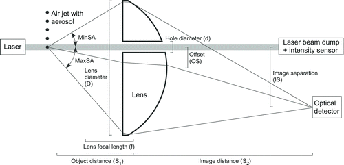
FIG. 1 Conceptual design of the new OPC. A laser beam crosses an imaging lens parallel to its optical axis via a hole drilled on the lens. The hole is offset from the lens optical axis. A particle-containing air jet transects the laser beam outside the lens focal plane. Laser light forward scattered by a particle is imaged to a point that is offset from the laser beam. An optical detector is used to measure the scattered light at the image spot. The optical detector signal can be related to the particle size given knowledge of refractive index.
There are scientific needs for accurate and size-resolved profiles of aerosol particle number and mass as a function of altitude into the lower stratosphere carried out routinely over a wide range of geographic locations. A safe means to measure the particle burden in the atmosphere perturbed by volcanic eruptions is needed for aviation management and could have a large economic impact. For example, Iceland's Eyjafjallajökull eruption on 14 April 2010 caused massive flight cancellations and airspace closures. A huge problem encountered during the event was the lack of reliable in situ volcanic-ash measurements. Small weather balloons are excellent platforms for temperature, ozone, and water vapor profile measurements. However, only a few particle sensors suitable for balloon deployment have been described in the literature (Hofmann et al. Citation1975; Hayashi et al. Citation1998; Sugita et al. Citation1999; Deshler et al. Citation2003; Kasai et al. Citation2003; Iwasaki et al. Citation2007; Hill et al. Citation2008). Most of these sensors are not capable of measuring particles below 150-nm diameter and/or are not suitable for disposable sondes. Since the aerosol accumulation mode in remote continental and free troposphere aerosol peaks at 100 and 250 nm, respectively, an instrument with a detection limit lower than 150 nm is highly desirable (Jaenicke Citation1993). Here, we report a low-cost, high-sensitivity OPC design that is suitable for balloon-borne as well as ground-based measurements and is capable of measuring particles smaller than 150 nm.
BASIC DESIGN CONCEPT
We have designed a novel OPC that detects the forward scattered light from individual particles. Since scattered light is generally the most concentrated at forward angles, this design optimizes collection of forward scattered light to achieve high sensitivity for small particle measurements. The critical issues of forward scattering detection are the separation of laser and scattered light and the collection of scattered light. We address both by using a modified, plano-convex, plastic lens as the imaging lens as shown in . The laser beam is aligned perpendicular to the imaging lens and offsets from the center of the lens by a small fraction of the lens radius. A small hole drilled in the lens allows the laser beam to pass through unimpeded. An air jet intersects the laser beam upstream of the lens back focal plane. When a particle in the jet enters the laser beam, it scatters laser light, mostly in the forward direction. The lens focuses the scattered light to a spot that is off-axis from the lens center on the opposite side of the drilled hole, leading to clear physical separation of the laser beam and focused scattered light.
Kiselev et al. (Citation2005) have reported a similar design. Instead of the modified lens in our design, they used a pair of custom-designed off-axis elliptical mirrors. The main advantages of our design are simplicity and low cost, making it suitable for a disposable or semi-disposable sonde instrument. A disadvantage to our design is that the angular range of light collection is limited by the numerical aperture of the lens.
Two types of lenses are suitable for the counter: an aspheric Fresnel lens (Edmund Optics, part number NT43-023) and an aspheric lens (Edmund Optics, part number NT66-013). Both have their respective advantages and disadvantages. The former has a larger numerical aperture and is physically thin. However, the numerous concentric rings of the Fresnel reduce the image quality. The latter provides good image quality and has an anti-reflection coating for efficient light collection. However, its smaller numerical aperture limits design flexibility. Both types of lens were tested for laser/scattered light separation and were found to produce satisfactory results. For the results presented here, only the aspheric lens was used.
Most of the parameters shown in are interdependent and collectively determine the performance and size of the counter. For example, placing the particle-containing air jet closer to the focal plane (i.e., decreasing S1) increases the amount of light collected by the lens and increases image separation from the laser beam (IS). However, image distance (S2) increases as well, leading to a larger instrument length dimension. The set of parameters in was chosen to ensure good light collection and reasonably small instrument size.
TABLE 1 Instrument parameters ()
The diameter of the hole drilled on the lens is an independent parameter. It defines the minimum light collection angle by the lens. The selection of its value is discussed in the next section.
PERFORMANCE ESTIMATE
Our targeted size range for detectable ambient aerosol is 100–2500 nm diameter, which covers the accumulation mode found in many places (Seinfeld and Pandis Citation1998) and has an upper limit that coincides with that of PM2.5 defined by the US Environmental Protection Agency. To build a useful instrument using our design, three critical issues must be addressed: (1) the instrument must be sensitive enough to detect particles at the lower size limit, (2) the optical sensor must have an adequate dynamic range for the entire size range, and (3) the instrument signal background from scattered light must be low enough for field and laboratory measurements of small particles. The first two issues are addressed theoretically in this section and the third issue is evaluated with the instrument prototype described in the following section.
Once the instrument geometry is set, the instrument sensitivity is determined by the wavelength and power density of the laser and the sensitivity of the optical sensor at that wavelength. To estimate sensitivity to a 100-nm particle, we assume a laser wavelength of 405 nm and a power density of 12 W cm−2, which corresponds to a 100-mW laser with a beam diameter of 1 mm. (Note that the real laser beam profile is nearly Gaussian. The 12 W cm−2 value is an approximation chosen for simplicity.) The relatively short wavelength of 405 nm is chosen for two reasons. First, at the lower end of the size range of interest (100 nm), scattered light intensity increases with decreasing wavelength in the visible and infrared region, so a shorter wavelength leads to higher instrument sensitivity. Second, inexpensive yet powerful diode lasers at 405 nm are readily available (). The scattering cross-section for a 100-nm diameter particle with an index of refraction of 1.52 (i.e., ammonium sulfate aerosol, commonly found in the troposphere) is 7 × 10⁻¹² cm2 according to Mie theory. With the optical geometry set as in and , approximately 12% of the scattered light is collected by the lens and focused onto the sensor. The power of the scattered light projected onto the detector through the lens is, therefore, about 1 × 10⁻¹¹ W. The radiant sensitivity of a typical photomultiplier tube (PMT) is 1.5 × 10⁵ A W−1 (Hamamatsu H10721-110) or higher. The resulting signal current is at least 1.4 μA, which is easily measurable with simple electronics. Thus, our design is theoretically sensitive enough to detect a 100-nm particle.
The dynamic range of the optical signal (defined as the ratio of the largest and smallest detectable peak heights) for a given particle size range can also be calculated using Mie theory. The relative amount of scattered light reaching the detector as a function of particle size is determined by the optical geometry. One example is given in (solid lines) using the geometry shown in with parameters listed in . Scattered light increases as a function of particle diameter to the sixth power when the particle diameter is less than about 400 nm. Above 400 nm, oscillations caused by Mie resonances (van de Hulst Citation1981) are apparent. These oscillations do not affect the detection of particles in this size range, but create ambiguity in the determination of particle diameter. As a consequence, wide size bins are typically chosen to include sizes that do not uniquely correspond to signal strengths as shown in .
FIG. 2 Relative scattering amplitude calculated using Mie theory as a function of particle diameter shown in (a) linear and (b) logarithmic scales. The laser wavelength is 405 nm and the index of refraction of particles is 1.52. Solid lines are calculated using the geometry shown in Figure 3 with a 4-mm hole diameter and with other parameters as listed in Table 1. Dashed and dotted lines correspond to Lens 2 hole diameters of 1 and 9 mm, respectively. Oscillations above 400 nm are due to Mie resonances. Vertical line pairs indicate diameter ranges where a scattering amplitude does not correspond to a unique particle diameter.
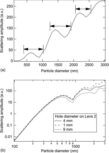
FIG. 3 Schematic of the laboratory prototype OPC. Drawing (except laser, lenses, and PMT) is to scale. Lens 1 specifications are 4-mm focal length and 0.6 numerical aperture (Edmund Optics, part number NT64-808). Lens 2 specifications are 17.5-mm focal length and 25.4-mm diameter (Edmund Optics, part number NT66-013).

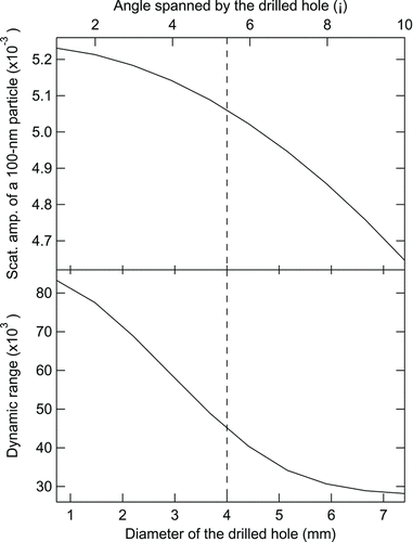
For a fixed geometry, the signal range depends on the particle size range and the diameter of the lens hole. As the particle size increases, the fraction of light scattered at near-forward angles increases. As the hole diameter increases, more of the near-forward scattered light is lost. This decreases the signal for large particles fractionally more than that for small particles, with the consequence that the dynamic range of the instrument decreases (, lower panel). Note that sensitivity for small particles also decreases as the hole diameter increases, albeit less strongly than for large particles (, upper panel). The selection of the hole diameter, therefore, is a compromise between sensitivity and signal dynamic range. The hole diameter also affects the appearance of Mie oscillations. Because of these oscillations, the actual upper limit of the detection range is about 2600 nm instead of 2500 nm. Below about 4.5-mm hole size, the curve minima and maxima locations are mostly hole-size independent. Above 4.5 mm, the curve minima and maxima locations become very hole-size dependent (). The signal dynamic range for the 100–2600 nm size range is shown in the bottom panel in as a function of the lens hole diameter. The dynamic range decreases substantially as hole diameter increases for holes smaller than about 5 mm. The reduction becomes insignificant when the hole diameter increases beyond about 5 mm. In this work, the diameter is set at 4 mm for good sensitivity, somewhat smaller signal dynamic range, and predictable Mie curve. As a result, the signal dynamic range is approximately 4.5 × 10⁴. This is smaller than the typical linear range of a PMT (1 × 10⁵ or larger) as defined by the ratio of its maximum output current to its dark current for a given gain setting. In practice, the linear range of the chosen sensor must also cover the entire peak of the smallest signal, which is about a factor of 10 (see the next section). With this consideration, the linear range of a PMT (or a combination of two detectors, see Jonsson et al. Citation1995) must be about 4.5 × 10⁵.
FIG. 4 Relative scattering amplitude and signal dynamic range (ratio of signal from 2600 nm particle to signal from 100 nm particle) as functions of the diameter of the drilled hole on the image lens for the configuration in Figure 3. The vertical dashed line indicates the diameter used in the prototype instrument.
Stratospheric aerosol is a mixture of sulfuric acid and water, with an index of refraction of 1.44–1.45 (Rosen and Hofmann Citation1986). Scattering from these aerosol particles is weaker than ammonium sulfate particles of equal size (∼27% less). The lower detection limit of the proposed instrument will be degraded (increased) by about 10%, if it is used for sulfuric acid aerosol measurements.
LABORATORY PROTOTYPE TESTS
In the previous section, our design was shown theoretically to be sensitive enough for detection of 100-nm particles. To achieve this, however, the instrument background noise must be below a certain threshold. Noise in an optical setup as shown in is usually dominated by laser light scattered by optical components and other surfaces, which is difficult to estimate. Since the laser beam spatial profile is usually close to a Gaussian, the time series of the optical signal induced by a particle transecting the laser beam at constant velocity is also close to Gaussian in shape. Particle diameter information is obtained from the signal waveform by fitting the peak and the background immediately before and after the peak with a Gaussian function. The signal-to-noise ratio (S/N) in the detection of a particle is defined in this work as the ratio of the Gaussian peak to the standard deviation of the instrument background noise. When the S/N is 10 or greater, the signal peak value and, hence, the particle size, can be reliably extracted via a Gaussian fit.
A laboratory prototype counter based on the schematic shown in and the key parameters listed in was built to test the S/N of the design. A 405-nm diode laser with output power rated at 100 mW was extracted from a laser module and used as the instrument light source. The laser could be operated at 75 mW without significant overheating by using a simple heat sink. The manufacturer's power supply did not supply a constant current to the laser, causing a ripple in the laser intensity on the order of a few percent. The power supply was replaced with a linear constant-current source (112 mA, 6.2 V across the laser, 8.5 V total). Lens 1 focuses the laser light to a point approximately 95 mm away on the optical axis. An accurate determination of the focal point location is difficult due to the large length/beam diameter ratio in this design. Two apertures, 1.8 and 1.3 mm in diameter, were placed ∼17 mm from the lens and at the approximate focal point, respectively. The first aperture acts as a spatial filter of the laser beam shape, and the second aperture is used to baffle the light scattered and refracted from the first aperture.
The laser beam diverges after the focal point near the second aperture, passes through the hole drilled on the imaging lens (Lens 2), and ends in a beam dump. An air jet containing particles is configured to intersect the laser beam approximately 25 mm away from the second aperture. The laser beam diameter at the intersection is about 0.5 mm based on the geometry shown in , but may be significantly smaller if the laser focal point is closer to the intersection point than the second aperture. The object-to-image distance ratio is approximately 5, leading to a separation of the laser beam from the image at the detector of about 18 mm. For simplicity, the air-jet nozzle is fixed on the instrument enclosure wall with no lateral adjustability (into and out of the paper in ). To ensure that the air jet crosses the laser beam, the nozzle is placed such that its tip is about 3 mm from the laser beam. The jet, expanding radially after exiting the nozzle, has a diameter larger than that of the laser beam when it intersects the beam. The flow rate of the air jet was 2–4 cm3 s−1. A significant disadvantage of this setup is that the scattering signals show much greater variability for a given particle size (Jonsson et al. Citation1995) than would occur with a narrow air jet transecting only the center portion of the laser beam. The variability is due to fact that the radial intensity distribution in a laser beam is close to a Gaussian. Thus, a particle transecting the center of the laser beam experiences a more intense light field than one transecting the beam edge.
TABLE 2 Estimated cost of a complete aerosol balloon instrument () in US dollars
A Hamamatsu H10720-01 PMT module (with similar performance characteristics to a Hamamatsu H10721-110 listed in ) was used for light sensing. The sensitivity of the PMT was set at approximately 1.5 × 10³ A W−1 (200 times lower than the recommended maximum value 3 × 10⁵) at 405 nm to suit the particle scattered light intensity. The PMT output current was converted to a voltage (range: −5 to 5 V, conversion factor: 1 V corresponds to 3.9 × 10⁻⁶ A) and digitized by a 12-bit digitizer. With the given electronic conversion factors, 1 V of output signal is equal to 4.1 × 10⁻⁶ A of the PMT output current and 2.9 × 10⁻⁹ W of laser power scattered onto the PMT by a particle. Note that the latter is estimated based on the PMT gain setting, which has not been calibrated. The PMT cathode is 8 mm in diameter, large enough that precise focusing of particle images onto the PMT cathode is not necessary.
For convenience, polystyrene latex (PSL) spheres were used for all of our experiments. The index of refraction of PSL spheres is 1.59, higher than our target value of 1.52. Near 100-nm diameter, PSLs scatter approximately 26% more light than spheres of the same size and index of refraction of 1.52. Although significant, this difference does not affect our conclusions concerning performance based on the experimental results presented below.
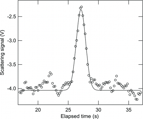
PSLs with diameters of 125 and 100 nm were nebulized, dried in low-humidity zero air, and passed through a differential mobility analyzer set at the same size as the PSLs in order to reduce the incidence of doublets. A typical signal for a 125-nm PSL is shown in along with a Gaussian fit. The peak-to-peak noise in the background is about 0.61 V, with a standard deviation of 0.12 V. At this noise level, the S/N for 125-nm PSLs is about 14 and, therefore, yields a reliable measurement. The S/N for a 125-nm particle with an index of refraction of 1.52 would be about 11 and should also be measured reliably. The noise in the signal is almost entirely due to scattered laser light. With the laser off, the detector noise is reduced to ±1 count.
FIG. 5 A time series of the optical signal produced by a 125-nm PSL particle and corresponding Gaussian fit.
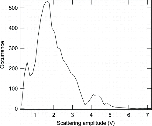
The distribution of 125-nm PSL peak heights is shown in . The distribution is quite broad, a consequence of the broad air jet transecting the entire laser beam (see above), with a peak at about 1.6 V. Peaks at 0.59 V and 4.1 V have much lower occurrence frequencies. The 0.59-V peak is an artifact related to background noise, which is occasionally high enough to pass as a particle signal. The origin of the 4.1-V peak is not clear. One possibility is doubly charged doublets. In the instrument calibration for measurement applications, the counts from the additional smaller peaks would be disregarded.
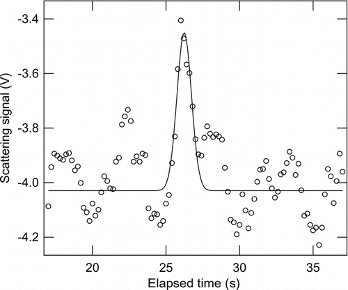
According to Mie theory, the scattering signal of a 100-nm particle is about four times smaller than that of a 125-nm particle of the same material. Indeed the most frequently observed peak heights from 100-nm PSLs are about 0.48 V, with an example peak shown in . Although the PMT is sensitive enough for 100-nm particle detection, retrieval of peak height frequency is not reliable with an S/N of only about 4. Similarly, 100-nm particles with an index of refraction of 1.52 (1.44, for an H2SO4/H2O mixture) would not be reliably detected based on an estimated S/N ∼ 3 (2.5).
FIG. 7 A time series of the optical signal produced by a 100-nm PSL particle and corresponding Gaussian fit.
The peak height of 0.48 V for a 100-nm PSL translates to a 660 W cm−2 average power density in the laser beam at the particle location. This value is 22 times higher than the value calculated from the laser power (75 mW) and estimated laser diameter at the aerosol–jet intersection (0.5 mm). The difference may be due to two causes. First, the PMT sensitivity used above is not based on a calibration and, hence, may be underestimated. Second, the laser power density at the aerosol–jet intersection strongly depends on the location of the laser focal point. As mentioned above, the focal point is not well determined in this prototype.
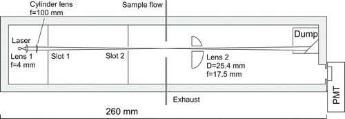
FIG. 8 Schematic of an OPC with design modification to address the mismatch in size between the laser beam and expanding aerosol jet at the point of intersection. The drawing (except laser, lenses, and PMT) is to scale. Lenses 1 and 2 are the same as in Figure 3. The cylinder lens specifications are 100-mm focal length and 12.5-mm diameter (Edmund Optics, part number NT48-356). The exhaust tubing diameter is reduced (Figure 3) to minimize aerosol jet expansion.
The prototype instrument is physically robust, in part due to the simplicity of the design. There are no spring-loaded components. All components that need to be movable for optical adjustment are secured with screws after adjustments. During 4 weeks of tests, the optical alignment remained unchanged after the components had been changed and modified and the instrument had been accidentally dropped several times from several centimeters.
The prototype is only intended for testing the optical design performance. The data presented here were taken by adapting the prototype to a commercially available Single Particle Soot Photometer (Schwarz et al. Citation2006), which provided an aerosol jet, fast digitizer (5 MHz), and associated data acquisition system. For a stand-alone instrument, a separate digitizer, a data system, and a pump with flow regulation are needed. For balloon applications, the data system will require in-flight data reduction to accommodate the limited communication bandwidth (i.e., the instrument will send size distributions to the ground instead of individual particle sizes). The power consumption of the prototype optical system is less than 2 W. Power estimates for the other major components are pump (1.2 W, Parker E134-11-120), data system (<5 W), flow control (∼3 W), and transmitter (0.5 W, iMet-1, International Met Systems, Grand Rapids, MI, USA). Additional power may also be needed for environmental control. Three C-size lithium batteries can provide 20 W of power for about 4 h, sufficient for all power needs including heating.
The gain of the PMT in the prototype used in these experiments was set intentionally high for a clear demonstration of the achievable S/N. If the device were to be used for ambient measurements, the gain of the PMT used would be reduced such that the signal of a 100-nm particle is about 0.024 V to maximize the size dynamic range.
The weight of the prototype optical system is 1 kg and can be easily halved by reducing the weight of the 6.35-mm thick aluminum enclosure walls. Additional weight will come from a small pump, flow controller, electronics, and transmitter for a balloon instrument. Overall, it is possible to limit the total weight to 2.5 kg, which is suitable for small weather balloon launches.
As mentioned above, one major shortfall of the prototype is that the air jet has a diameter larger than that of the laser beam. Although simple in construction, the current configuration requires significant effort of characterization and calibration (Jonsson et al. Citation1995). shows a proposed design that eliminates this shortfall. In this design, Lens 1 is used to collimate the diode laser output into a parallel beam with a diameter of about 2.5 mm. A cylinder lens placed after Lens 1 focuses the circular laser beam into one with a rectangular cross-section that is about 0.1 mm thick and 2.5 mm wide at the air nozzle. The inner diameter of the nozzle is 0.5 mm. Sample air existing the nozzle will expand somewhat, but should still be much narrower than the laser sheet width. The cost estimate for this design is given in . Laser beam-shaping apertures shown in will be replaced with two slots to accommodate the noncircular shape of the laser beam.
NOISE REDUCTION
The results shown in and indicate that noise must be reduced by a factor of about 3 to achieve reliable measurements of 100-nm particles. In the prototype instrument, the background noise arises from two principal sources: scattered light from the apertures and the beam dump. It is not clear which source dominates. Both are painted black to absorb light and reduce scattering. The optical reflectance of the paint used in this work is rated at 4% (MH2200 Black Paint, Alion Science and Technology, McLean, VA, USA). There are a number of ways to further reduce the light noise level. First, better light absorbing coatings are available. For example, Laser Black (Epner Technology, Inc., Brooklyn, NY, USA) has a reflectance of 1.5% at 405 nm. National Aeronautics and Space Administration (NASA) has developed a new coating with a reflectance of only 0.5% (http://www.nasa.gov/topics/technology/features/new-nano.html). Second, the current diameter of the second aperture was chosen for ease of alignment. It can be reduced by at least a factor of 2 and possibly more. With the diameter halved, the noise will be reduced by a factor of 2 (if reflection from the rim of the second aperture dominates) to 4 (if light from the first aperture dominates). Third, the beam dump can be improved. A commercial beam dump (Newport Corp model PL15) reduced the noise by 20% from the level shown in and , thus increased the S/N number reported in the previous section by 25%. However, even with this, new dump diffusive reflection of the laser light can still be seen by the naked eye in a fully lit room. This suggests that there is significant room for the improvement of the beam dump. If all three improvements are implemented, background noise should be reduced by a factor of 5–24, sufficient for measurements of 100-nm particles (S/N ∼ 15–72). It is worth noting that if instrument size (and, therefore, weight) is not limited (such as in ground-based applications), simply doubling the optical path lengths by using a 50-mm lens may reduce the noise by a factor of 4. This is due to the fact that the intensity of the light noise decreases as the square of the distance between the light noise sources and the detector. If the 50-mm lens (such as Edmund Optics, part number NT32-589) has a numerical aperture similar to that of the 25-mm lens in the prototype, the change of the image magnification will be small. The requirement of active area of the PMT therefore remains unchanged.
CONCLUSIONS
A novel OPC has been designed and a prototype constructed and evaluated. The design incorporates a powerful and inexpensive laser operating at 405 nm. Scattered light from sampled particles is collected with an off-axis lens that has a hole drilled to pass the laser beam to a dump. This provides the needed physical separation between the laser beam and detected particle signal. The prototype demonstrated that PSL particles as small as 125-nm diameter can be reliably measured. A theoretical estimate indicates a lower detection limit near 100 nm. This limit may be achieved with further reduction in background noise from scattered laser light. A principal limitation of this design is the need for a detailed calibration of the detection efficiency due to the small size of the laser beam compared with the ambient air jet at the point of intersection with the laser beam. A modified design is proposed to mitigate this limitation.
Principal objectives of the design were simplicity, low weight, and low cost, thereby making the instrument suitable for disposable or semi-disposable balloon-borne applications in the troposphere and stratosphere. The maximum dimension of the prototype is about 30 cm including the PMT, but without thermal insulation. The power requirement is estimated to be less than 25 W. Total instrument weight is less certain, but could likely be below 2.5 kg. These parameters make the proposed instrument small and light enough for hand-launch balloons that could be used to measure particle distributions and trends in the background atmosphere. Our proposed instrument is ideal for in situ volcanic-ash measurements. Since the ash mass is concentrated at large sizes (∼10 μm; Schumann et al. Citation2011), a PMT is not necessary, leading to a significant reduction in cost.
Acknowledgments
This work was supported by the National Oceanic and Atmospheric Administration (NOAA) Atmospheric Composition and Climate Program and the NOAA Health of the Atmosphere Program. We thank J. A. Ogren and K. K. Kelly for insightful discussions.
REFERENCES
- Albrecht , B. A. 1989 . Aerosols, Cloud Microphysics, and Fractional Cloudiness . Science , 245 : 1227 – 1230 .
- Anderson , T. L. , Charlson , R. J. , Schwartz , S. E. , Knutti , R. , Boucher , O. Rodhe , H. 2003 . Climate Forcing by Aerosols-A Hazy Picture . Science , 300 : 1103 – 1104 .
- Chung , C. E. , Ramanathan , V. , Carmichael , G. , Kulkarni , S. , Tang , Y. Adhikary , B. 2010 . Anthropogenic Aerosol Radiative Forcing in Asia Derived from Regional Models with Atmospheric and Aerosol Data Assimilation . Atmos. Chem. Phys. , 10 : 6007 – 6024 .
- Curtis , L. , Rea , W. , Smith-Willis , P. , Fenyves , E. and Pan , Y. 2006 . Adverse Health Effects of Outdoor Air Pollutants . Environ. International , 32 : 815 – 830 .
- Deshler , T. , Hervig , M. E. , Hofmann , D. J. , Rosen , J. M. and Liley , J. B. 2003 . Thirty Years of in Situ Stratospheric Aerosol Size Distribution Measurements from Laramie, Wyoming (41° N), Using Balloon-Borne Instruments . J. Geophys. Res. , 108 ( D5 ) : 4167
- Gucker , F. T Jr. , O’Konski , C. T. , Pickard , H. B. and Pitts , J. N., Jr. 1947 . A Photoelectronic Counter for Colloidal Particles . J. Am. Chem. Soc. , 69 : 2422 – 2431 .
- Hayashi , M. , Iwasaka , Y. , Watanabe , M. , Shibata , T. , Fujiwara , M. Adachi , H. 1998 . Size and Number Concentration of Liquid PSCs Balloon-Borne Measurements at Ny-Aalesund, Norway in Winter of 1994/95 . J. Meteorol. Soc. Japan , 76 : 549 – 560 .
- Haywood , J. and Boucher , O. 2000 . Estimates of the Direct and Indirect Radiative Forcing Due to Tropospheric Aerosols: A Review . Rev. Geophys. , 38 : 513 – 543 .
- Hill , M. K. , Brooks , B. J. , Norris , S. J. , Smith , M. H. , Brooks , I. M. and De Leeuw , G. 2008 . A Compact Lightweight Aerosol Spectrometer Probe (CLASP) . J. Atmos. Ocean. Tech. , 25 : 1996 – 2006 .
- Hofmann , D. J. , Rosen , J. M. , Pepin , T. J. and Pinnick , R. G. 1975 . Stratospheric Aerosol Measurements, I, Time Variations at Northern Midlatitudes . J. Atmos. Sci. , 32 : 1446 – 1456 .
- Intergovernmental Panel on Climate Change . 2007 . Climate Change 2007: The Physical Science Basis, in Contribution of Working Group I to the Fourth Assessment Report of the Intergovernmental Panel on Climate Change , Edited by: Solomon , S. 996 Cambridge , , U.K. : Cambridge Univ. Press .
- Iwasaki , S. , Maruyama , K. , Hayashi , M. , Ogino , S.-Y. , Ishimoto , H. Tachibana , Y. 2007 . Characteristics of Aerosol and Cloud Particle Size Distributions in the Tropical Tropopause Layer Measured with Optical Particle Counter and Lidar . Atmos. Chem. Phys. , 7 : 3507 – 3518 .
- Jaenicke , R. 1993 . “ Tropospheric Aerosols ” . In Aerosol-Cloud-Climate Interactions , Edited by: Hobbs , P. V. 1 – 31 . San Diego , CA : Academic Press .
- Jonsson , H. H. , Wilson , J. C. , Brock , C. A. , Knollenberg , R. G. , Newton , R. Dye , J. E. 1995 . Performance of the Focused Cavity Aerosol Spectrometer for Measurements in the Stratosphere of Particle Size in the 0.06–2 Micrometer Diameter Range . J. Atmos. Oceanic Technol. , 12 : 115 – 129 .
- Kasai , T. , Tsuchiya , M. , Takami , K. , Hayasi , M. and Iwasaka , Y. 2003 . Balloon Borne Optical Particle Counter for Stratospheric Observation . Rev. Sci. Instrum. , 74 : 1082 – 1092 .
- Keeler , G. J. , Morishita , M. and Young , L.-H. 2005 . Characterization of Complex Mixtures in Urban Atmospheres for Inhalation Exposure Studies . Exp. Toxic. Path. , 57 : 19 – 29 .
- Kiselev , A. , Wex , H. , Stratmann , F. , Nadeev , A. and Karpushenko , D. 2005 . White-Light Optical Particle Spectrometer for in Situ Measurements of Condensational Growth of Aerosol Particles . Appl. Opt. , 44 : 4693 – 4701 .
- Knollenberg , R. G. 1970 . The Optical Array: An Alternative to Scattering or Extinction for Airborne Particle Size Determination . J. Appl. Met. , 9 : 86 – 103 .
- Mie , G. 1908 . Beiträge zur Optik trüber Medien, speziell kolloidaler Metallösungen, Leipzig . Ann. Phys. , 330 : 377 – 445 .
- Patterson , H. S. and Whytlaw-Gray , R. 1926 . The Scattering of Light by Individual Particles in Smoke . Proc. R. Soc. Lond., Ser. A. , 113 : 312 – 322 .
- Pincus , R. and Baker , M. 1994 . Precipitation, Solar Absorption, and Albedo Susceptibility in Marine Boundary Layer Clouds . Nature , 372 : 250 – 252 .
- Rosen , J. and Hofmann , D. J. 1986 . Optical Modeling of Stratospheric Aerosols: Present Status . Appl. Opt. , 25 : 410 – 419 .
- Schleusener , S. A. 1968 . Automatic High Speed Particle Sizing Using a Gas Laser . Rev. Sci. Instrum. , 39 : 1916 – 1919 .
- Schumann , U. , Weinzierl , B. , Reitebuch , O. , Schlager , H. , Minikin , A. Forster , C. 2011 . Airborne Observations of the Eyjafjalla Volcano Ash Cloud Over Europe During Air Space Closure in April and May 2010 . Atmos. Chem. Phys. , 11 : 2245 – 2279 .
- Schwarz , J. P. , Gao , R. S. , Fahey , D. W. , Thomson , D. S. , Watts , L. A. Wilson , J. C. 2006 . Single-Particle Measurements of Midlatitude Black Carbon and Light-Scattering Aerosols from the Boundary Layer to the Lower Stratosphere . J. Geophys. Res. , , 111:C00E03
- Seinfeld , J. H. and Pandis , S. N. 1998 . Atmospheric Chemistry and Physics (Chapter 7) , New York : John Wiley & Sons . pp. 431–439
- Sugita , T. , Kondo , Y. , Koike , M. , Kanada , M. , Toriyama , N. Nakajima , H. 1999 . Balloon-Borne Optical Counter for in Situ Aerosol Measurements . J. Atmos. Chem. , 32 : 183 – 204 .
- Twomey , S. 1974 . Pollution and the Planetary Albedo . Atmos., Environ. , 8 : 1251 – 1256 .
- van de Hulst , H. C. 1981 . Light Scattering by Small Particles (Chapter 10.52) , New York : Dover Publications, Inc . p. 155
