Abstract
Multiplexed electrospray is a promising aerosol generation technique to produce high throughput quasi-monodisperse droplets in the nanometer and micron size range. Here we report the design, fabrication, analysis, and performance of a linear electrospray (LINES) system. The fabrication of the nozzle array is based on a precision computer numerical control (CNC) micromachining platform with 1-micron resolution. This rapid prototyping approach offers the flexibility of creating devices from a wide range of materials including metals and polymers with packing densities on par with silicon microfabrication at 20 sources/cm for LINES devices and 460 sources/cm2 for the two-dimensional array. The LINES device uses a slot extractor design to simplify alignment and enhance operation robustness. We also used dummy nozzles (posts without fluidic channels) to offset edge effect on electric field and improved droplet size uniformity. We derived the approximate spray expansion model from charge conservation and Gauss’ law. We applied the line-of-charge approximation to establish scaling laws for prescribing operating conditions. The devices show excellent droplet size uniformity from source to source, with relative standard deviation (RSD) of primary droplets <3%.
Copyright 2013 American Association for Aerosol Research
1. INTRODUCTION
Electrospray (ES) is a simple approach to generate aerosol of quasi-monodisperse, electrically charged droplets. The range of droplet sizes that can be produced by ES is from hundreds of microns in diameter to molecular dimensions. In addition, the droplet size can be tightly controlled by adjusting operating parameters such as liquid flow rate and electrical conductivity. While operating in the so-called cone-jet mode (Cloupeau and Prunet-Foch Citation1989), the ES exhibits an unmatched ability to produce an aerosol containing quasi-monodisperse particles, especially in the nanometer size range (Fernandez de la Mora et al. 1990; Tang and Gomez Citation1994; Chen et al. 1995). However, the size of the droplets generated is monotonically dependent on the flow rate used to establish the cone-jet (Rosell-Llompart and Fernandez de la Mora Citation1994; Tang and Gomez Citation1994; Chen and Pui Citation1997). Therefore, in applications demanding smaller droplets, the mass flow-rate consequently becomes minuscule (Gomez et al. Citation1998). Thus, multiplexed electrospray (MES) devices become indispensable in overcoming the bottleneck of low throughput ES systems while preserving the small and uniform droplet size. In addition, the high aspect ratio micron sized features of typical ES emitters pose significant manufacturing challenges in meeting these tolerances. Thus, a reliable design with a flexible fabrication process for MES devices is needed.
The primary design constraints of the device are the need for equal electric and flow fields at each cone-jet site. Published work on MES devices can be broadly categorized by electrode configuration and fabrication approach. There are two main electrode configurations for MES devices: emitter-collector and distributor-extractor-collector (Borra et al. Citation1997, Citation1999). The three electrode configuration is crucial to enable operation of high nozzle packing densities in the cone-jet mode, effectively dividing the device into two electric field regions so that space charge can be mitigated to provide equal electric fields at each cone-jet site (Deng and Gomez Citation2007). To date, at least four various fabrication routes to MES have been attempted: (1) “brute force,” where multiple individual stainless steel (Snarski and Dunn Citation1991; Rulison and Flagan Citation1993; Regele et al. Citation2002; Hubacz and Marijnissen Citation2003; Jaworek et al. Citation2006; Si et al. Citation2007) or fused silica (Kelly et al. Citation2008) capillaries are integrated together into a single device; (2) silicon microfabrication (Xue et al. Citation1997; Tai et al. Citation2002; Xiong et al. Citation2002; Deng at al. Citation2006; Velazquez-Garcia et al. Citation2006; Kim et al. Citation2007; Mao et al. Citation2011); (3) soft lithography (Kim et al. Citation2001; Wang et al. Citation2004; Choi et al. Citation2011); and (4) conventional machining (Almekinders and Jones Citation1999; Tang et al. Citation2001; Bocanegra et al. 2006; Duby et al. Citation2006; Si et al. Citation2010; Arnanthigo et al. Citation2011; Lhernould and Lambert Citation2011).
We previously demonstrated a silicon microfabricated multiplexed electrospray emitter array with a packing density up to 10,000 sources/cm2 (Deng et al. Citation2009), as well as an increase in throughput by two orders of magnitude while preserving the monodispersity (Deng et al. 2006). Recently, the charged droplets interaction in a densely packed electrospray array has been numerically studied (Yang et al. Citation2012) using a supercomputer based on Graphics Processing Units (GPU).
Despite those progresses, only handful applications have been reported based on MES microfabricated from silicon. Those application examples include: a high power-density liquid fuel micro-combustor (Deng et al. Citation2007), synthesis of biodegradable PLGA micro- and nanoparticles (Almeria et al. Citation2010, 2011), high efficiency cooling for microelectronics (Deng and Gomez 2011), and an ion thruster for compact space propulsion (Lenguito et al. Citation2010). The slow adoption of silicon based MES is due to several limitations brought by silicon. First of all, successful fabrications of silicon nozzles require expensive capital equipments, dedicated clean room facilities, and steep learning curves for aerosol scientists. Second, the fabrication process (deep reactive ion etching, or DRIE) makes the silicon chip extremely fragile, with high rate of failure during packaging and even ultrasonication cleaning. Lastly, different applications require non-silicon materials. For example, Teflon may be preferred for certain conditions because it is chemically inert and shows large contact angle for many fluids; transparent materials such as polycarbonate may be desired for optofluidics devices (Erickson et al. Citation2011); strong metals such as stainless steel may become the materials of choice when high stress and high temperature are present.
Here we report a simple, rapid, and low-cost approach of fabricating compact MES emitter array using a lab-built precision CNC machining platform. In comparison with silicon micro fabrication, the precision CNC machining process offers the flexibility of fabricating high packing density devices from a wide range of materials beyond silicon, including metals and polymers. Moreover, we adopted the slot-extractor design that makes the operation more stable and robust. Experimentally, we reached packing density of 460 sources/cm2, with uniform primary droplet diameter from source to source. Numerically, this article used the numerical code developed in (Yang et al. Citation2012) and studied the spray evolution of a linear array.
2. DEVICE DESIGN, FABRICATION, MODELING, AND CHARACTERIZATION
2.1. Electrode and Fluidic Design
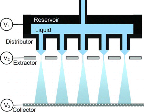
To attain identical operation from source to source, localized and equal electric field around each emitter is crucial. Previous successful MES devices (Bocanegra et al. 2005; Deng et al. Citation2006) achieved operation in the cone-jet mode at high source packing densities by using the distributor-extractor-collector configuration (Borra et al. Citation1997, Citation1999), effectively separating the MES device into two isolated electric field regions: the cone-jet forming region and spray region (). The distributor is the nozzle-bearing electrode which initiates the spray by uniformly dividing the flow to each nozzle tip where cone-jets form. The extractor is an electrostatic barrier electrode between the distributor and collector that protects the vulnerable cone-jet forming region from the space charge created by droplets in the spray region. The collector is the electrode furthest downstream where droplets are collected.
FIG. 1 The distributor-extractor-collector configuration of multiplexed electrospray (Deng et al. Citation2006). (Color figure available online.)
A good electrode design should also address the “edge effect” (Deng et al. Citation2006), which refers to the fact that the nozzles at the edge of the array experience more intense electric filed and “pull” more liquid flow rates at the edge nozzles. The higher flow rates at the edge will lead to significantly larger droplet diameters and should be avoided. The strategy we used in this work is to introduce extra dummy nozzles (posts without a microfluidic channels) on the edge, which offset the edge effect and further improve the electric field uniformity.
We focused on creating compact linear arrays, because numerical simulation has shown that to achieve uniform deposition using MES, it is best to use a linear array combined with linear motion of the substrate (Yang et al. Citation2012).
For the extractor electrode, we adopted slot geometry (Velazquez-Garcia et al. Citation2006; Lhernould and Lambert Citation2011) over hole geometry for simpler alignment and better resistance to liquid flooding at the extractor.
The fluidic design was guided by the design rule established in Deng et al. Citation2009. Briefly, this rule states that if approximately equal flow fields are desired for all nozzles, the viscous pressure drop through the channel (governed by the Hagen-Poiseuille flow solution), must be comparable to the electrohydrodynamic pulling pressure, which is comparable to γ/OD, where γ is the surface tension coefficient of the liquid, and OD is the nozzle outer diameter. Meanwhile, the fluidic design needs to be compatible with the geometry of the machining tools. Commercial tungsten carbide drills and endmills are available in the micron size range with aspect ratios up to 10:1. Here we chose nozzle inner diameter ID = 50 μm, micro-channel length L = 500 μm, and outer diameter OD = 120 μm. We have verified that those geometries satisfy the above mentioned design rule with ethanol running at ∼1 mL/h/nozzle.
2.2. Device Fabrication
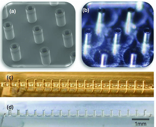
To expedite the prototyping cycle and reduce the cost associated with silicon microfabrication, we developed a precision machining platform and process specifically for MES fabrication. Three linear stages (Newport TS-series) were retrofit with 36:1 geared stepper motors, and assembled into an XYZ configuration with 1 μm space resolution. A precision high-speed spindle (NSK) capable of 25,000 RPMs was mounted onto the platform. Fifty micrometer (50 μm) diameter microdrills and 250 μm diameter endmills (Kyocera) were used to machine the inner and outer nozzle diameters, respectively. The MES device was first designed using SolidWorks and then the CAD model was converted to machine-readable g-code using CAMWorks. The g-code was executed using the open-source CNC control software (EMC2). After machining, nozzles were post-treated by etching in a dilute HCl solution to assist removal of any remaining burrs that would cause irregularities in the electric and flow fields. Finally the components were cleaned in ethanol ultrasonication bath. Several examples of finished devices are shown in .
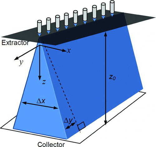
2.3. Approximate Spray Profile Model
shows a schematic of the LINES device illustrating the orientation of the axes. We derived a spray profile model (Yang et al. Citation2012) to describe how the spray from a linear nozzle source expands along the x direction. We make the following assumptions to simplify the real problem into a manageable one:
| i. | The spray consists of monodisperse, mutually charged droplets. In other words, we only consider the primary droplets and neglect the satellite droplets, which typically account for only ∼1% or less of the total spray mass. The droplet inertia is negligible, therefore the droplet motion is dictated by | ||||
| ii. | The axial velocity of the droplet, u, is constant (Deng and Gomez Citation2007). | ||||
| iii. | The volumetric charge density ρ does not vary along the radial direction, i.e., ∂ρ/∂r=0. | ||||
| iv. | The x component of the space charge field, | ||||
At steady state, the law of charge conservation is ![]() . Using
. Using ![]() and Gauss's law
and Gauss's law ![]() , and notice ∂ρ/∂x≈0, we reach Zρ2/ϵ0+u∂ρ/∂z=0. The solution to this equation is:
, and notice ∂ρ/∂x≈0, we reach Zρ2/ϵ0+u∂ρ/∂z=0. The solution to this equation is:
The y-expansion is primarily determined by the spray axis bending, caused by the repelling force exerted by other sprays (Snarski and Dunn Citation1991). By approximating the spray as a line-of-charge (Deng and Gomez Citation2007), we can treat axis bending of the spray at the edge as the result of E y, which is the radial component of the electric field introduced by all other line-of-charge:
The spray axis separation velocity is:
2.4. Modeling of Minimum Driving Field
To avoid droplet fly-back (Deng and Gomez Citation2007), the driving field Ed applied between the extractor and collector must exceed a critical value Ec , otherwise droplets will accumulate and eventually flood the extractor, inhibiting operation. The value of Ec is equal to the maximum space charge field that appears in the “critical zone” right after the spray passes through the extractor (x ∼ 0, z ∼ 0) at close proximity to the center of the spray. Again, we use the line-of-charge approximation, and note the center spray as the 0th spray (assuming an odd number of nozzles) while the ith pair includes the two sprays at a distance iP0 from the center. The z component field Ec,i near the “critical zone” caused by the ith group is
2.5. Numerical Simulation
The numerical simulation of the spray interaction was conducted using a Lagrangian droplet tracking model executed on a GPU supercomputer (Yang et al. Citation2012). The model simulates the trajectory of all droplets just after jet break-up. Lagrangian method has been well-documented previously (Ganan-Calvo et al. Citation1994; Hartman et al. Citation1999; Wilhelm et al. 2003; Deng and Gomez Citation2007; Oh et al. Citation2008) and the details will not be repeated here.
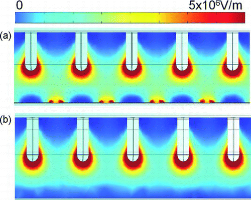
The electric fields generated by different electrode design were simulated using COMSOL Multiphysics. To model the nozzle geometry, cylinders with the same height, and outer diameter as the nozzles in the 51 nozzle device were used, but spherical caps were superimposed at the tip to simulate a conductive liquid meniscus.
2.6. Device Characterizations
The fluid used in this work was 200 proof ethanol with electric conductivity of 1.6 × 10⁻⁵ S/m. The working flow rate range tested for pure ethanol through a single nozzle in the cone-jet mode was 0.2–1 mL/h. The operating environment was air at atmospheric pressure. No charge neutralization mechanism was introduced.
The droplet size at each individual electrospray source across the 51 nozzle array was measured using Phase Doppler Interferometry (Artium). To measure the size and velocity of the droplets emanating from each nozzle, the device was mounted on a 3-axis micrometer to position the spray cloud in the PDI probe volume. For each spray, we positioned the laser probe volume at or near the spray axis. Although the point measurement only gave the size of the primary droplets, this size is representative because the primary droplets have dominant mass in a cone-jet electrospray. We took 2,000 primary droplet samples and recorded the simply averaged droplet diameter D10.
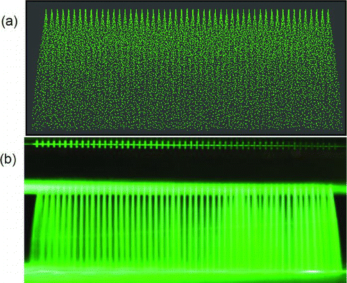
The spray was visualized by shining a 532 nm laser sheet on the x-z or y-z plane. The images of the spray profile were taken using a digital camera (Canon T2) with a macro lens (Sigma) at relatively long exposure time to trace the droplet trajectory.
3. RESULTS AND DISCUSSION
3.1. Electric Fields Comparison between Hole and Slot Extractors
Two simulations were performed using extractors spaced 375 μm away from the tip of the nozzles. One used an extractor with 500 μm diameter holes and another with a slot of 500 μm opening width. The boundary condition at the extractor surface was ground potential and high potential at the nozzle surface. The simulation results () show that nozzles at potential of 1.2 kV using a hole extractor produces almost identical electric field as those nozzles at 1.3 kV using a slot extractor. The modest increase in required voltage for slot configuration is acceptable because the slot extractor brings the benefits of alignment ease and higher tolerance to accidental flooding.
3.2. Spray Profiles
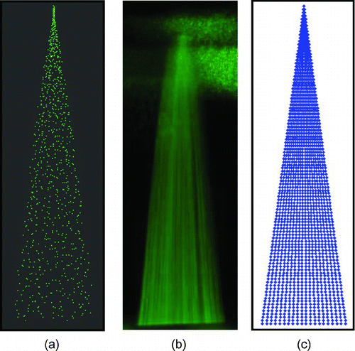
shows the spray profile on the x-z plane from numerical simulation, experiment, and profile model EquationEquation (5). All results are in good agreement, showing the profile on x-z plane resembles an isosceles triangle.
FIG. 5 The x-z spray profile from (a) numerical simulation, (b) experiment, and (c) EquationEquation (3). (Color figure available online.)
shows the spray profile on the y-z plane from numerical simulation and experiment. The dark region in is caused by the blockage of the extractor structure. The experiment result agrees well with the simulation, showing the profile on y-z plane resembles an isosceles trapezoidal. Moreover, for N = 51, P 0 = 0.5 mm, the typical value of Δy is 1.7 mm, which is insignificant compared to the value of original total spray width (NP 0 = 25.5 mm).
3.3. Droplet Size Uniformity
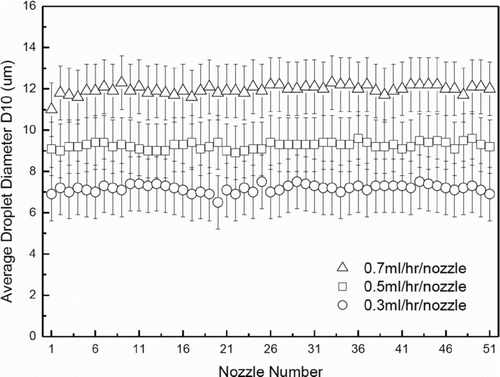
shows the primary droplet diameter data at each individual spray of the 51-nozzle array at 0.3, 0.5, and 0.7 mL/h/nozzle. The uncertainty of the PDI diameter measurement is ±1.3 μm. Clearly, the average droplet diameter for each source remained uniform across the array, showing a maximum relative standard deviation of 3% at 0.3 mL/h/nozzle. The data confirmed that the high performance in terms of droplet size uniformity across all nozzles for the LINES device.
4. CONCLUSION
We report the design, fabrication, analysis and performance of a linear electrospray (LINES) system. The nozzle array is fabricated on a precision CNC micromachining platform, which produces packing densities on par with silicon microfabrication at 20 sources/cm for LINES devices and 460 sources/cm2 for the two-dimensional array. The devices show excellent primary droplet size uniformity from source to source, with RSD <3% at flow rates from 0.3 to 0.7 mL/h/source.
More importantly, a wide range of CNC machinable materials can be processed by this approach. For example, metals such as aluminum or brass can be used to ease the device handling because silicon is relatively fragile. Polymers such as polycarbonate can be used when the working fluid is acidic which prevents the use of metals. In addition, CNC machinable stock materials do not have the thickness limit faced by silicon wafers (∼1 mm), therefore, the device can be designed and machined for more compact systems level packaging.
We note that the CNC machining is a series process instead of parallel fabrications such as lithography. The machining time of the entire nozzle array is the product of number of nozzles and the time needed for each nozzle. It takes about 2 min for our in-house built CNC to machine a single nozzle, and about 2 h to machine the 51-nozzle array. This relatively long machining time is due to the low speed of our inexpensive linear stages (∼$2,000 each axis) based on lead screws and stepper motors. The machining time can be reduced by at least an order of magnitude by using high-speed, high-precision piezo linear stages, which cost about $10,000 per axis. The smallest nozzle inner diameter is limited by the finest drill commercially available (currently 25 μm). The packing density is limited by the smallest endmill available (currently 100 μm). It is also worth noticing that it is very convenient for CNC to fabricate tapered nozzles, because the 45° end mills are commercially available. A tapered nozzle effectively makes the tip outer diameter nearly identical to the inner diameter, which can help suppress evaporation when volatile liquids or very low flow rates are required (Lenguito et al. Citation2010).
Because of the uniform primary droplet diameter, rapid fabrication process, ease of alignment, robust operation, and a wide selection of materials, we expect the LINES devices be an emerging aerosol generation tool in many important applications such as thin film deposition, roll-to-roll manufacturing, and materials synthesis.
Acknowledgments
We thank Professor Alessandro Gomez for his advice on the post-treatment of the machined nozzles; we also thank Dr. Jian Liu for his help regarding precision micromilling. Financial support from the Office of Research and Commercialization at the University of Central Florida is appreciated.
REFERENCES
- Almekinders , J. C. and Jones , C. 1999 . Multiple Jet Electrohydrodynamic Spraying and Applications . J. Aerosol Sci. , 30 : 969 – 971 .
- Almería , B. , Deng , W. , Fahmy , T. M. and Gomez , A. 2010 . Controlling the Morphology of Electrospray-Generated PLGA Microparticles for Drug Delivery . J. Colloid Interf. Sci. , 343 : 125 – 133 .
- Arnanthigo , Y. , Yurteri , C. U. , Biskos , G. , Marjinissen , J. C. M. and Schmidt-Ott , A. 2011 . Out-Scaling Electrohydrodynamics Atomization Systems for the Production of Well Defined Droplets . Powder Technol. , 214 : 382 – 387 .
- Bocanegra , R. , Galan , D. , Marquez , M. , Loscertales , I. G. and Barrero , A. 2005 . Multiple Electrosprays Emitted from an Array of Holes . J. Aerosol Sci. , 36 : 1387 – 1399 .
- Borra , J. P. , Camelot , D. , Marijnissen , J. C. M. and Scarlett , B. 1997 . A New Production Process of Powders with Defined Properties by Electrohydrodynamic Atomization of Liquids and Post-Production Electrical Mixing . J. Electrostat. , 40–41 : 633 – 638 .
- Borra , J. P. , Camelot , D. , Chou , K. L. , Kooyman , P. J. , Marijnissen , J. C. M. and Scarlett , B. 1999 . Bipolar Coagulation for Powder Production . J. Aerosol Sci. , 30(7) : 945 – 958 .
- Chen , D. and Pui , D. Y. H. 1997 . Experimental Investigation of Scaling Laws for Electrospraying: Dielectric Constant Effect . Aerosol Sci. Tech. , 27 ( 3 ) : 367 – 380 .
- Chen , D. , Pui , D. Y. H. and Kaufman , S. L. 1995 . Electrospraying of Conducting Liquids for Monodisperse Aerosol Generation in the 4 nm to 1.8 μm Diameter Range . J. Aerosol Sci. , 26 : 963 – 977 .
- Choi , K. H. , Rahman , K. , Khan , A. and Kim , D. S. 2011 . Cross-Talk Effect in Electrostatic Based Capillary Array Nozzles . J. Mech. Sci. Technol. , 25 ( 12 ) : 3035 – 3062 .
- Cloupeau , M. and Prunet-Foch , B. 1989 . Electrostatic Spraying of Liquids in Cone-Jet Mode . J. Electrostat. , 22 ( 2 ) : 135 – 159 .
- Deng , W. , Klemic , J. F. , Li , X. , Reed , M. and Gomez , A. 2006 . Increase of Electrospray Throughput Using Multiplexed Microfabricated Sources for the Scalable Generation of Monodisperse Droplets . J. Aerosol Sci. , 37 : 696 – 714 .
- Deng , W. and Gomez , A. 2007 . Influence of Space Charge on the Scale-up of Multiplexed Electrosprays . J. Aerosol Sci. , 38 : 1062 – 1078 .
- Deng , W. , Klemic , J. F. , Li , X. , Reed , M. and Gomez , A. 2007 . Liquid Fuel Combustor Miniaturization via Microfabrication . Proc. Combustion Inst , 31 : 2239 – 2246 .
- Deng , W. , Waits , C. M. , Morgan , B. and Gomez , A. 2009 . Compact Multiplexing of Monodisperse Electrosprays . J. Aerosol Sci. , 40 : 907 – 918 .
- Deng , W. and Gomez , A. 2011 . Electrospray Cooling for Microelectronics . Int. J. Heat Mass Tran. , 54 : 2270 – 2275 .
- Duby , M. H. , Deng , W. , Kim , K. , Gomez , T. and Gomez , A. 2006 . Stabilization of Monodisperse Electrosprays in the Multi-Jet Mode via Electric Field Enhancement . J. Aerosol Sci. , 37 : 306 – 322 .
- Fernández de la Mora , J. , Navascués , J. , Fernándes , F. and Rosell-Llompart , J. 1990 . Generation of Submicron Monodisperse Aerosol by Electrosprays . J. of Aerosol Sci. , 21(S) : S673 – S676 .
- Erickson , D. , Serey , X. , Chen , Y.-F. and Mandal , S. 2011 . Review: Nanomanipulation Using Near Field Photonics . Lab-on-a-Chip , 11 : 995 – 1009 .
- Ganan-Calvo , A. M. , Lasheras , J. C. , Davila , J. and Barrero , A. 1994 . Electrostatic Spray Emitted from an Electrified Conical Meniscus . J. Aerosol Sci. , 25 : 1121 – 1142 .
- Gomez , A. , Bingham , D. , De Juan , L. and Tang , K. 1998 . Production of Protein Nanoparticles by Electrospray Drying . J. Aerosol Sci. , 29 ( 5–6 ) : 561 – 574 .
- Hartman , R. P. A. , Borra , J. P. , Brunner , D. J. , Marijnissen , J. C. M. and Scarlett , B. 1999 . Evolution of Electrohydrodynamic Sprays Produced in Cone-Jet Mode, A Physical Model . J. Electrostat. , 47 : 143 – 170 .
- Hubacz , A. N. and Marijnissen , J. C. M. 2003 . The Scale-up of Electrohydrodynamic Atomization . J. Aerosol Sci. , 33 : 1471 – 1479 .
- Jaworek , A. , Lackowski , M. , Krupa , A. and Czech , T. 2006 . Electrostatic Interaction of Free EHD Jets . Exp. Fluids , 40 : 568 – 576 .
- Kim , J. S. and Knapp , D. R. 2001 . Miniaturized Multichannel Electrospray Ionization Emitters on Poly(dimethylsiloxane) Microfluidic Devices . Electrophoresis , 22 : 3993 – 3999 .
- Kim , W. , Guo , M. , Yang , P. and Wang , D. 2007 . Microfabricated Monolithic Multinozzle Emitters for Nanoelectrospray Mass Spectrometry . Anal. Chem. , 79 : 3703 – 3707 .
- Kelly , R. T. , Page , J. S. , Zhao , R. , Qian , W. J. , Mottaz , H. M. Tang , K. 2008 . Capillary-Based Multi Nanoelectrospray Emitters: Improvements in Ion Transmission Efficiency and Implementation with Capillary Reversed-Phase LC-ESI-MS . Anal. Chem. , 80 : 143 – 149 .
- Lhernould , M. S. and Lambert , P. 2011 . Compact Polymer Multi-Nozzles Electrospray Device with Integrated Microfluidic Feeding System . J. Electrostat. , 69 ( 4 ) : 313 – 319 .
- Lenguito , G. , Fernandez de la Mora , J. and Gomez , A. 2010 . Multiplexed Electrospray for Space Propulsion Applications, 46th AIAA Joint Propulsion Conference . AIAA-2010–6521, July 25–28.
- Mao , P. , Wang , H. T. , Yang , P. and Wang , D. 2011 . Multinozzle Emitter Arrays for Nanoelectrospray Mass Spectrometry . Anal. Chem. , 83 : 6082 – 6089 .
- Oh , H. , Kim , K. and Kim , S. 2008 . Characterization of Deposition Patterns Produced by Twin-Nozzle Electrospray . J. Aerosol Sci. , 39 ( 9 ) : 801 – 813 .
- Regele , J. D. , Papac , M. J. , Rickard , M. J. A. and Dunn-Rankin , D. 2002 . Effects of Capillary Spacing on EHD Spraying from an Array of Cone Jets . J. Aerosol Sci. , 33 : 1471 – 1479 .
- Rosell-Llompart , J. and Fernandez de la Mora , J. 1994 . Generation of Monodisperse Droplets 0.3 to 4 mm in Diameter from Electrified Cone-Jets of Highly Conducting and Viscous Liquids . J. Aerosol Sci. , 52 : 1093 – 1119 .
- Rulison , A. J. and Flagan , R. C. 1993 . Scale-up of Electrospray Atomization Using Linear Arrays of Taylor Cones . Rev. Sci. Instrum. , 64 : 683 – 686 .
- Si , B. Q. T. , Byun , D. and Lee , S. 2007 . Experimental and Theoretical Study of a Cone-Jet for an Electrospray Microthruster Considering the Interference Effect in an Array of Nozzles . J. Aerosol Sci. , 38 : 924 – 934 .
- Si , B. Q. T. , Byun , D. , Nguyen , V. D. , Yudistira , H. T. , Yu , M. J. Lee , K. H. 2010 . Polymer-based electrospray device with multiple nozzles to minimize end effect phenomenon . J. Electrostat. , 68 : 138 – 144 .
- Snarski , S. R. and Dunn , P. E. 1991 . Experiments Characterizing the Interaction between Sprays of Electrically Charged Liquid Droplets . Exp. Fluids , 11 : 268 – 278 .
- Tai , Y. C. , Xie , J. , He , Q. , Liu , J. and Lee , T. 2002 . Integrated Micro/Nano Fluidics for Mass-Spectrometry Protein Analysis . Int. J. Nonlin. Sci. Num. Simul. , 3 : 739 – 741 .
- Tang , K. and Gomez , A. 1994 . On the Structure of an Electrostatic Spray of Monodisperse Droplets . Physics of Fluids , 6 : 2317 – 2332 .
- Tang , K. , Lin , Y. , Matson , D. W. , Kim , T. and Smith , R. D. 2001 . Generation of Multiple Electrosprays Using Microfabricated Emitter Arrays for Improved Mass Spectrometric Sensitivity . Anal. Chem. , 73 ( 8 ) : 1658 – 1663 .
- Velásquez-García , L. F. , Akinwande , A. I. and Martínez-Sánchez , M. 2006 . A Micro-Fabricated Linear Array of Electrospray Emitters for Thruster Applications . J. Microelectromech. Sys., , 15 ( 5 ) : 1260 – 1271 .
- Wang , Y. X. , Cooper , J. W. , Leec , C. S. and DeVoe , D. L. 2004 . Efficient Electrospray Ionization from Polymer Microchannels Using Integrated Hydrophobic Membranes . LabChip. , 4 : 363 – 367 .
- Wilhelm , O. , Mädler , L. and Pratsinis , S. E. 2003 . Electrospray Evaporation and Deposition . J. Aerosol Sci. , 34 : 815 – 836 .
- Xiong , J. , Zhaoying , Z. , Xiongying , Y. , Xiaohao , W. , Feng , Y. and Lib , Y. 2002 . A Colloid Micro-Thruster System . Microelectron Eng. , 61–62 : 1031 – 1037 .
- Xue , Q. , Foret , F. , Dunayevskiy , Y. M. , Zavracky , P. M. , McGruer , N. E. and Karger , B. L. 1997 . Multichannel Microchip Electrospray Mass Spectrometry . Anal. Chem. , 69 : 426 – 430 .
- Yang , W. , Lojewski , B. , Wei , Y. and Deng , W. 2012 . Interactions and Deposition Patterns of Multiplexed Electrosprays . J. Aerosol Sci. , 46 : 20 – 33 .
