Abstract
Aircraft-based aerosol sampling in clouds is complicated by the generation of shatter artifact particles from aerodynamic or impaction breakup of cloud droplets and ice particles in and around the aerosol inlet. Aerodynamic breakup occurs when the Weber number of a droplet, which primarily depends on the droplet size and the magnitude of the relative motion of the droplet and the local air mass, exceeds a critical value. Impaction breakup of a droplet occurs when the droplet's impaction breakup parameter, K, which is a combination of Weber and Ohnesorge numbers, exceeds a critical value. Considering these two mechanisms, the critical breakup diameters are estimated for two aerosol inlets of different designs—a conventional forward-facing solid diffuser inlet (SDI) and a cross-flow sampling sub-micron aerosol inlet (SMAI). From numerical simulations, it is determined that cloud droplets of all sizes will experience impaction breakup in SDI, while only droplets larger than ∼16 μm will experience impaction breakup in SMAI. The relatively better in-cloud sampling performance of SMAI is because of its cone design that slows the flow just upstream of the sample tube. The slowing upstream flow, however, causes aerodynamic breakup of drops larger than ∼100 μm. The critical breakup diameters determined from analysis of field data largely validate numerical predictions. The cross-flow sampling design of SMAI is seen to ensure that shatter artifacts in the inlet are minimal even when there are a significant number of particles larger that the critical breakup size. The study results, thus, suggest that the SMAI design presents an effective approach to sample interstitial particles from aircraft.
© 2013 American Association for Aerosol Research
1. INTRODUCTION
Aerosol role in cloud formation and the subsequent interaction of cloud droplets with the incoming solar radiation, i.e., the aerosol indirect effect, must be well understood to accurately determine the global radiative budget (Seinfeld and Pandis Citation2006; Denman et al. Citation2007; Andreae and Rosenfeld Citation2008). The aerosol indirect effect is modulated by the properties of the cloud system, i.e., the number concentration and the mean size of the cloud droplets formed, which in turn are dependent on the properties of the aerosol population initially present in the cloud-forming air mass (Rogers and Yau Citation1989; Seinfeld and Pandis Citation2006). Aerosol–cloud interaction can also determine the lifetime and fate of a cloud system. The contact of sub-freezing aerosol particles with super-cooled cloud droplets can trigger ice formation through contact nucleation and initiate precipitation and, thus, alter the cloud system (Lohmann Citation2002). Also, as aerosols repeatedly activate and pass through cloud events, aqueous-phase processing and photochemical reactions can alter the nature of the aerosol population (Ervens et al. Citation2008). The ability to model the formation and evolution of cloud systems and the transformation of aerosol populations during cloud events is critical for large-scale global climate and regional air quality studies. The development and validation of such models requires data from a wide range of aerosol–cloud systems and such data can, often, only be obtained from aircraft-based measurements.
Complete characterization of aerosol particles and cloud droplets from aircraft require the deployment of a large number of instruments. Cloud droplet instruments are located outside the aircraft, where they sample passively from the freestream. The large sizes of the cloud droplets make in situ passive measurements both necessary, because these particles cannot be sampled efficiently through any length of tubing, and sufficient, because physical characterization is possible with relatively open instruments. Aerosol measurements, however, often require large instruments that can only be located inside the fuselage. Accurate aerosol measurements are, therefore, dependent on the ability to representatively sample particles from outside the aircraft and efficiently transport them to the cabin. While reasonably error-free sampling is possible in clear air, in-cloud sampling is complicated by the interaction of cloud droplets with aerosol inlets. The shatter of cloud droplets in and around an aerosol inlet can result in the generation of a large number of shatter artifact particles and contamination of the aerosol sample (Hudson and Frisbie Citation1991; Hudson Citation1993; Weber et al. Citation1998; CitationCraig et al. in press). Thus, aircraft-based analysis of interstitial particle population properties has largely been impossible.
The extent of the shatter artifact problem has been seen to depend on droplet properties, inlet geometry, and aircraft conditions. By comparing aerosol measurements from two forward-facing aerosol inlets of different sizes, Weber et al. (Citation1998) determined that shatter artifacts were larger for an inlet with a smaller leading-edge diameter. From wind tunnel tests, Twohy et al. (Citation2003) established that the number of shatter particles generated increased with airspeed. With most aerosol inlets, the extent of the shatter problem is different in warm and cold clouds, with the shatter problem, generally, less significant with ice particles than liquid droplets (Weber et al. Citation1998; CitationCraig et al. in press). Droplet shatter has also been a problem for cloud and precipitation measurements (Gardiner and Hallett Citation1985; Field et al. Citation2003; Korolev and Isaac Citation2005; Jensen et al. Citation2009), but advances in cloud probe tip designs and introduction of new high-speed data analyses approaches have helped alleviate some of these problems related to size distribution measurements of activated droplets (Korolev and Isaac Citation2005; Lawson Citation2011). There have, however, been very limited efforts to address the problems related to aircraft-based aerosol measurements in clouds.
FIG. 1 Schematic diagram of shatter artifact generation for different liquid cloud droplet breakup mechanisms (cross-section of SMAI).
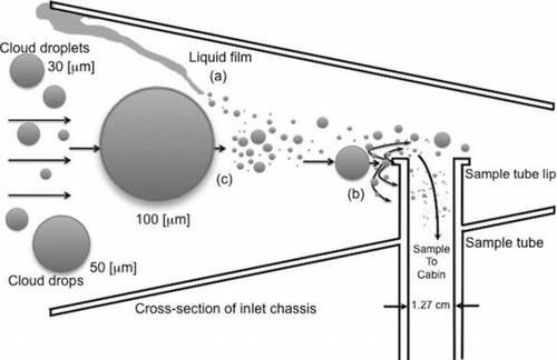
An illustration of the different liquid cloud droplet shatter mechanisms relevant to aerosol inlet sampling is shown in . Droplets can breakup upon impaction on solid surfaces or because of adverse aerodynamic forces in the freestream. When a liquid droplet impacts on a surface, it may rebound, spread over the surface, or shatter (Rein Citation1993; Mao et al. Citation1997; Rioboo et al. Citation2002; Yarin Citation2006). The exact nature of the droplet response upon impaction depends on droplet properties (e.g., surface tension, viscosity, and size), impaction velocity, and surface conditions (Mundo et al. Citation1995; Yarin and Weiss Citation1995; Mao et al. Citation1997; Rioboo et al. Citation2001; Yarin Citation2006). A droplet impacting on a surface will begin to spread out radially from the point of impaction (Mao et al. Citation1997; Rioboo et al. Citation2002) and, depending on the contact angle, the liquid layer may recoil back to the impaction point and rebound (nonwetting surfaces), or for low contact angles (wetting surfaces), stay on the surface as a film (Mao et al. Citation1997; Rioboo et al. Citation2001). The size of the film increases with increasing impaction velocity and droplet size and decreases with increasing droplet viscosity (Mao et al. Citation1997; Rioboo et al. Citation2002). For surfaces with finite dimensions, the film could move toward the edge of the surface, where it can eventually become unattached and spray into secondary droplets (; Gardiner and Hallett Citation1985; Lawson and Cooper Citation1990; Emery et al. Citation2004). Additionally, when a droplet impacts with high momentum, the film may become unstable as it spreads out (Lin and Reitz Citation1998) and break up, producing secondary droplets (; Mundo et al. Citation1995; Yarin and Weiss Citation1995; Rioboo et al. Citation2001; Yarin Citation2006). For aircraft-based measurements, this impaction breakup case is the most relevant.
The impaction breakup of liquid droplets is governed by the droplet Weber and Reynolds numbers. If the impacting surface is wet, the presence of the film suppresses secondary droplet generation relative to a dry surface case (Cossali et al. Citation1997; Wang and Chen Citation2000; Rioboo et al. Citation2003). A surface can be considered dry, if the ratio of the surface film thickness to the droplet diameter (H) is small (<∼0.1; Wang and Chen Citation2000). For aerosol inlets on aircraft, because of the large droplet impaction velocities and the low concentrations of the impacting activated droplets, the surface is expected to remain dry after droplet impaction (Povarov and Rastorguev Citation1986).
From experiments of individual liquid droplets impacting on a dry surface, Mundo et al. (Citation1995) determined that the fate of impacting droplets depended on the value of their impaction parameter, K, defined as
If the K value of droplets impacting on a surface is more than the critical value (K crit) of 57.7, then the droplets will shatter; else they will just deposit on the surface and form a liquid film (Mundo et al. Citation1995). Corresponding to the K crit value, a critical wall impaction breakup diameter, D crit,wall, i.e., the critical diameter for wall impaction breakup, can be calculated for known inlet dimensions and sampling conditions. Only droplets larger than this critical size will shatter on impaction. For K > K crit, the number of secondary particles generated from droplet shatter increases highly nonlinearly with the value of K (O’Rourke and Amsden Citation2000), and the mean size and standard deviation of the size distribution of the secondary droplets decreases (Mundo et al. Citation1995).
Cloud droplets traveling toward an inlet may shatter even without impacting on a surface. When the velocities of a droplet and the local air flow are mismatched, the resulting shear on the droplet surface could generate instabilities (Pilch and Erdman Citation1987; Hsiang and Faeth Citation1992) causing droplet breakup and secondary particle generation, as illustrated in . This aerodynamic breakup process is governed by the droplet's aerodynamic Weber number defined as
In addition to impaction and aerodynamic breakup, other possible cloud droplet breakup mechanisms are multi-stage breakup process in which in-coming cloud droplets collide with shattered droplets, which are then subject to further breakup; and aerodynamic breakup after the cloud drop has impacted and shattered on the surface. These shatter mechanisms are likely to be important only under conditions of very high cloud concentrations or when aircraft speeds are much higher, and are not relevant for the current analysis.
In this study, critical cloud droplet breakup sizes, considering aerodynamic and wall impaction breakup mechanisms, are determined from numerical simulations for two aerosol inlets of different designs—a conventional forward-facing aerosol inlet, the Solid Diffuser Inlet (SDI), and a cross-flow inlet, the Sub-Micron Aerosol Inlet (SMAI), which has recently shown promise for interstitial aerosol sampling. The model results are validated with aircraft data obtained from simultaneous operation of the two inlets.
2. FIELD DATA FOR ANALYSIS
The SMAI and SDI aerosol inlets were both simultaneously deployed on the NSF/NCAR C-130 aircraft during the VAMOS Ocean-Cloud-Atmosphere-Land Study (VOCALS) field project during Summer 2008, off the coast of Chile, South America. Analysis of the aerosol number concentration measurements made with the two inlets during this project provides a good basis to assess the relative performance of the two inlets. The schematic diagrams of the SMAI and SDI inlets are shown in . The SDI () is a forward-facing, one-stage diffusing aerosol inlet, with a shroud to align the flow entering the inlet. The diameter of the shroud is 3.14 cm and the entrance diameter of the inlet is 0.51 cm, which then expands to a diameter of 4.47 cm at an angle of 4.5° (Huebert et al. Citation2004; McNaughton et al. Citation2007). The sampling efficiency of this inlet has been characterized by Huebert et al. (Citation2004) and McNaughton et al. (Citation2007), and inlet cut size was determined to be ∼3–5 μm, aerodynamic diameter. During VOCALS, the SDI was mounted on the side of the aircraft, extending 30.5 cm from the surface of the aircraft skin. The inlet flow was actively controlled to ensure isokinetic-sampling conditions.
FIG. 2 Size comparison of the two aerosol inlets flown on the C-130 during VOCALS: (a) SDI and (b) SMAI. The drawings are not to scale.
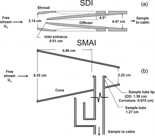
The main feature of the SMAI () design is a flow-through cone facing the freestream flow, with the cone entrance diameter (6.35 cm) being significantly larger (∼12×) than that of the SDI. Inside the cone, a perpendicular sampling tube of inner diameter of 1.27 cm is located at a distance of 6.86 cm from the entrance. The perpendicular sampling tube contains a flat-plate sample tube lip that is oriented largely parallel to the bulk flow in the cone. The sample tube lip has an outer diameter of 1.59 cm and a radius of curvature of 0.875 cm. A sample flow rate of 20 lpm is drawn through the perpendicular sample tube, of which 5 lpm is sub-sampled to the instruments in the cabin and the excess flow is expelled out through a scarf tube (Beaton and Spowart Citation2012; CitationCraig et al. in press). The SMAI sampling characteristics were numerically determined by CitationCraig et al. (in press) and the inlet cut size was determined to be ∼3 μm. The SMAI was placed on the belly of the aircraft, just ahead of the back-bay doors, with the center of the cone located ∼46 cm from the aircraft skin. Condensation nuclei (CN) measurements were made downstream of the SDI and SMAI by identical condensation particle counters (CPCs; TSI 3760a; TSI Inc., St. Paul, MN, USA). In clear air (i.e., in the absence of clouds), the CN measurements made by the two inlets—SDI and SMAI—were seen to be very consistent (CitationCraig et al. in press).
To characterize the performance of the two aerosol inlets in clouds, specific cloud events were identified from measurements of two wing-mounted in situ cloud probes: the Cloud Droplet Probe (CDP; Droplet Measurement Technologies (DMT), Inc., Boulder, CO, USA) and the 2-Dimensional Cloud probe (2D-C; Particle Measuring Systems [PMS], Inc., Boulder, CO, USA). The CDP cloud droplet number concentration (CDNCCDP) was used to identify small cloud droplet events with sizes ranging between 2 and 50 μm, while the 2D-C concentration (CDNC2DC) was used to derive large cloud droplet events with droplet sizes between 62.5 and 1537.5 μm. During VOCALS, the CDP measurements were in good agreement with that of the Forward Scattering Spectrometer Probe (FSSP-100; PMS, Inc.). Full range bead calibrations of the in situ cloud probes and flow calibrations of the TSI CN counters were conducted pre- and post-project. A summary of the aerosol and cloud instrumentation discussed in this article is provided in .
TABLE 1 Aerosol inlets and cloud probes flown on the C-130 during VOCALS
3. COMPUTATIONAL FLUID DYNAMIC (CFD) DROPLET BREAKUP PREDICTIONS
To evaluate the critical breakup diameters for aerosol inlets considering aerodynamic and wall impaction mechanisms, knowledge of the flow field in and around the inlets is required. As the SDI operates isokinetically and isoaxially, the streamlines can be assumed to be straight lines headed straight toward the inlet and the droplet velocities can be assumed to be the same as that of the flow. Droplets headed toward the inlet can impact on the shroud and the leading edge of the inlet (i.e., the inlet tip). The impaction of droplets on the shroud can be ignored, because any secondary particles generated there will largely remain close to the shroud, and away from the sample flow streamlines. Only shatter particles generated from droplet impaction breakup at the inlet tip will likely contaminate the aerosol sample. The critical impaction droplet diameter will, thus, be determined based on the entrance tip dimensions. In the isokinetic-sampling SDI, the particle and the flow velocities will be matched and hence no aerodynamic droplet breakup is expected upstream of the inlet. It is, however, possible for large droplets that enter the SDI to breakup aerodynamically when the flow slows down inside the inlet. The critical aerodynamic breakup diameters for SDI will, thus, be estimated considering the inlet diffuser section.
3.1. SMAI Flow Pattern
The SMAI flow field is more complicated than the SDI's and the knowledge of the exact flow field is critical for accurate determination of critical breakup diameters. The CFD software, FLUENT® (ANSYS, Inc., Lebanon, NH, USA) is used to calculate the three-dimensional flow field in and around the SMAI, with the flow treated as steady, compressible, and turbulent. The turbulence in the flow was modeled using the two-equation standard k-ϵ turbulence model (the Reynolds number based on the average SMAI cone diameter of 4.3 cm is ∼105). A large, external hemisphere of radius 51 cm was selected as the extent of the modeling domain around the SMAI. At the finest grid resolution, the domain was divided into a total of ∼1.3 million tetrahedral cells. The boundary conditions far from the SMAI were typically chosen to match typical C-130 flight conditions during VOCALS: i.e., an ambient pressure of 875 mb, a static temperature of 283 K, and Mach number of 0.325 (108 m s−1). In addition to these conditions, to determine the effect of aircraft velocities on the inlet performance, the simulations were repeated for Mach numbers of 0.3 (100 m s−1) and 0.4 (135 m s−1).
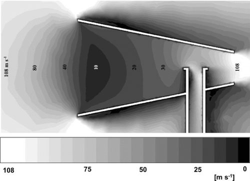
The CFD results of the velocity field in and around the SMAI for the Mach number case of 0.325 are shown in . The combination of a small flow through the SMAI (relative to that directed toward the inlet) and the large size of the cone entrance results in a region of high pressure just upstream of the inlet. The cone, therefore, acts as a virtual blunt body that decelerates the flow upstream of the inlet, with the gas velocity reaching a minimal value of ∼10 m s−1 just after the cone entrance. Inside the cone, the velocity increases and the flow reaches a velocity of ∼40 m s−1 at the location of the sample tube.
FIG. 3 CFD calculations of velocity magnitude in and around the SMAI (cross-sectional view) for the Mach number case of 0.325.
3.1.1. Breakup Predictions
In order to determine the critical breakup diameters for each mechanism, the trajectories of liquid water droplets over a size range of 1–500 μm were tracked from the freestream to the sample tube. The droplets were injected far upstream of the inlet with velocities matched to the local flow conditions. Because of their large sizes, cloud droplets traversing through regions of large gas velocity gradients have finite Reynolds numbers and thus, a Reynolds-number-dependent particle drag coefficient is used for the droplet trajectory calculations (Hinds Citation1999; Baron and Willeke Citation2005). The combination of small residence time of the droplets in the vicinity of the inlet surface and their large sizes makes turbulent dispersion unimportant for the current simulations. The trajectories are, therefore, calculated only considering the mean-flow velocities. The density of the tracked droplets was increased until the results remained invariant with the number of injections.
3.1.1.1. Aerodynamic breakup
To characterize aerodynamic breakup in SMAI, the aerodynamic Weber numbers, Weaero, were calculated along the droplet trajectories, starting from a location well upstream of the cone entrance (−30 cm) to downstream of the sample tube (+8 cm) and these values were compared against the critical breakup value. Upstream of the cone, the Weaero numbers were calculated within the area bounded by the diameter of the cone entrance, while inside the inlet, the spatial extent of the calculations were restricted by the cone geometry.
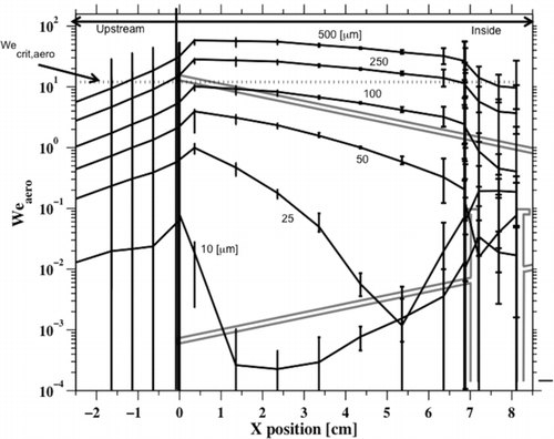
At a selected axial location (X) within the bounded area, drops of a given size will have a range of Weaero numbers corresponding to the radial variation in the flow velocities. The average, minimum, and maximum Weaero numbers at an axial location are calculated for different drop sizes and are shown in . For a selected droplet diameter, Weaero increases as the droplet approaches the inlet entrance. This is because, as the gas decelerates upstream of the inlet, the finite relaxation times of the large droplets will result in significant relative velocities for the particles compared to that of the local air mass. Proportional to the particle relaxation times, the Weaero numbers increase with particle diameters. The maximum droplet Weaero number is at the entrance to the cone, where the gas velocity is the lowest. Thus, the smallest droplet diameter that will shatter, i.e., D crit,aero, must be determined from the Weaero values at the cone entrance. From the CFD flow field calculations, the D crit,aero value for SMAI is determined to be ∼100 μm, with droplets smaller than this size able to enter the inlet without experiencing aerodynamic breakup. The Weber number of droplets larger than 100 μm will exceed the critical value upstream of the cone entrance and these particles will, thus, shatter prior to entering the inlet and contribute to shatter artifacts in the sample flow. At higher aircraft velocities, the critical droplet sizes decrease, and making it more likely for even smaller droplets to shatter aerodynamically. For SDI, the aerodynamic breakup region is inside the inlet where the flow slows down and the critical size calculated assuming freestream droplet velocities and an average sample flow velocity inside the inlet is ∼100 μm, similar to the SMAI.
FIG. 4 Weaero values calculated as a function of liquid cloud droplet diameters in the regions upstream of the cone entrance and inside the cone. Negative X locations indicate upstream of the SMAI, while positive X locations indicate inside the SMAI. For a selected X location, maximum, minimum, and average droplet Weaero numbers were determined. The outline of the SMAI is also shown to help visualize the aerodynamic breakup region. The critical Weber number, Wecrit,aero, of 12 is indicated for reference.
3.1.1.2. Wall impingement
While droplets smaller than 100 μm will enter the SMAI without shattering aerodynamically, some of these droplets may breakup when they impact on the inlet walls, if their K value exceeds K crit. Possible impaction surfaces include the outer rim of the cone, inside walls of the cone, and the sample tube lip. The only shatter-generated secondary droplets likely to be aspired into the perpendicular sample tube are those generated from impaction on the sample tube lip. The D crit,wall values for SMAI are, therefore, calculated based on conditions at this location. For SDI, considering isoaxial- and isokinetic-sampling conditions, the K values are calculated assuming that the droplets impact with the freestream velocity at the critical impaction area, the leading edge of the inlet (i.e., the inlet tip). The K values as a function of droplet diameter for the SMAI and SDI are shown in .
FIG. 5 Wall impaction parameter (K) as a function of droplet diameter (D d) for SDI and SMAI. For SDI, the impaction velocities for droplets were set as 108 m s−1. For the SMAI, the error bar for each droplet diameter represents the range of K values corresponding to the different impaction locations around the sample tube lip. Note that the x-component of the droplet velocity was used as the orthogonal impaction velocity, U d. The critical K value, K crit, of 57.7 is indicated.
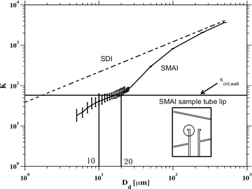
The impaction K values increase with droplet diameter because larger droplets impact with greater kinetic energies and, thus, breakup more easily. The presence of the high pressure region upstream of the SMAI helps droplets relax to the slowing flow conditions, and lowers their momentum prior to reaching the sample tube lip, i.e., lowers the droplet K values. Thus, compared to the SDI, the critical impaction diameters for the SMAI are much larger. The D crit,wall value for SDI is ∼2 μm, while for SMAI it is ∼10–20 μm. For the SMAI, a range of critical droplet diameters exists, because the impaction velocities of the droplets vary over the different sample tube lip locations.
As almost all cloud droplets will impact and shatter on the SDI, the SDI sample will always be contaminated in clouds. For SMAI, CFD predictions suggest droplets as large as 100 μm can enter the inlet without experiencing aerodynamic breakup, though droplets in the diameter range of 20–100 μm may impact on the sample tube lip and generate shatter artifacts.
4. EXPERIMENTAL RESULTS
The CFD predictions of critical breakup diameters for the two inlets can be validated from analysis of aircraft measurements of aerosol number concentrations made with the two inlets during the VOCALS campaign. The in-cloud sampling performance of the inlets will be characterized using an enhancement factor, E, defined as (CitationCraig et al. in press)
In clouds, because of the activation of some background particles to form droplets, the interstitial aerosol concentration should be lower than the background CN concentration, and, thus, in the absence of shatter artifacts, the measured enhancement factors should be <1. The enhancement factors are used to determine the in-cloud sampling performance of SMAI and SDI for two distinct cloud cases: (1) small cloud droplet events, when only droplets smaller than 50 μm were present and (2) large cloud drop events, when the only drops present were larger than 50 μm.
4.1. Small Cloud Droplet Events
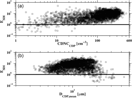
The performance of the SDI in cloud systems where the mean droplet sizes are only in the range of 2–50 μm (i.e., when no drops are recorded by 2D-C) is shown in . For all CDP cloud concentrations, the SDI enhancements, E SDI, are greater than 1 and enhancements are seen to increase with the mean cloud droplet diameter, D CDP,mean (obtained from CDP measurements). Consistent with CFD predictions, aerosol concentrations measured by the SDI inside clouds are significantly enhanced for all cloud droplet sizes. Thus, in-cloud aerosol measurements are not possible with the SDI and other similar forward-facing isokinetic aerosol inlets.
FIG. 6 The calculated E SDI for cloud systems containing only small cloud droplets (i.e., no drizzle). The enhancements are shown as a function of (a) cloud droplet number concentration from the CDP, CDNCCDP, and (b) mean CDP cloud droplet diameter, D CDP,mean. The points represent 1 s data.
For the case of small cloud droplet events, the SMAI enhancements, E SMAI, are shown in . The SMAI enhancements are significantly reduced compared to that of the SDI. The E SMAI values decrease with increasing cloud concentrations, consistent with the expectation of reduced interstitial aerosol in clouds as the concentration of activated particles is increased. The E SMAI values are seen to increase with increasing D CDP,mean.
FIG. 7 The calculated E SMAI for cloud systems containing only small cloud droplets (i.e., no drizzle) as a function of (a) CDP cloud droplet number concentration and (b) CDP mean cloud droplet diameter. The points represent 1 s data.
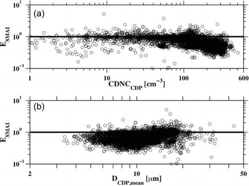
At a selected mean cloud droplet diameter, a significant variability in the E SMAI values is observed () and this can be attributed to (1) possible inaccuracies in the estimation of CNbg values, and/or (2) statistical fluctuations in incident drop sizes. Accurate estimate of CNbg will require knowledge of cloud base CN concentrations and consideration of possible dilution of CN concentrations because of mixing of in-cloud and out-of-cloud air masses and entrainment of descending air mass. Thus, E values greater than 1 may represent an under prediction of CNbg concentrations rather than shatter from the inlet. In addition, for the same mean size, a range of different cloud droplet size distributions are possible, particularly with variable number of large particles in the tail of the distribution. Thus, in an inlet sample volume, the likelihood of encountering large sized droplets that could shatter will differ with the cloudy air mass, resulting in variable inlet enhancement values. Relative to the differences in the magnitude of the E values for the two inlets, the variability in the values is insignificant and, hence, can be ignored.
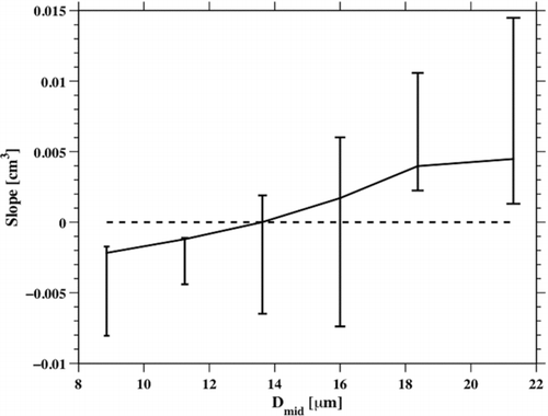
To predict the critical breakup diameter from experimental data, time periods corresponding to a narrow range of total CDP concentration (say, 54 cm−3 ± 10%) were identified. During these time periods, while the total CDP concentrations are nearly constant, the size distributions could be quite variable. The variation in SMAI enhancements during these time periods was correlated with CDP concentrations in different size bins (mid-point bin diameters, D mid, of 8.88, 11.25, 13.63, 16.00, 18.38, and 21.30 μm). The resultant slopes of a linear fit to this correlation (E SMAI vs. CDP bin concentration) were determined and are shown in . The uncertainty bars in the plot correspond to the range of slope values obtained at the different total cloud concentrations (54, 110, 130, 200, 230, 300, and 340 cm−3 ± 10%). When the mean cloud droplet sizes are smaller than ∼14 μm, the expected relationship of decreasing SMAI CN concentration with increasing cloud concentration (i.e., negative slope) is observed. When the mean cloud droplet sizes are larger than ∼18 μm, increasing the cloud concentrations is seen to result in increasing SMAI CN concentration for all cloud concentrations (i.e., positive slope). This analysis suggests that the critical cloud droplet diameter for breakup is ∼16 μm, and with bigger droplets likely to contribute to shatter artifacts, largely consistent with CFD simulations.
4.2. Large Cloud Drop Events
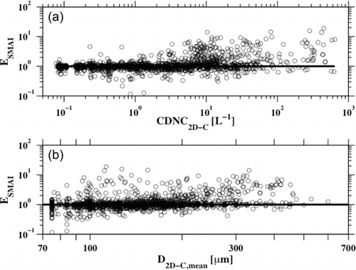
The performance of SMAI when only drizzle was present (i.e., drops were detected by 2D-C, but no droplets were detected by the CDP) is shown in . In general, SMAI CN enhancements are seen to increase with cloud concentration, but no clear trend with cloud drop size is observed, and no obvious evidence of aerodynamic breakup is visible. Even in the presence of drops much larger than the critical impaction and aerodynamic size, enhancement values less than 1 are observed. To explain these observations, a Monte Carlo-based simulation was conducted to determine the number of cloud drops intercepted by the critical impaction and aerodynamic breakup zones as a function of cloud number concentration. For impaction breakup, the critical zone was considered as the area of the central part of the sample tube lip (1.6e-2 cm2), over which most of the sample flow passed through. For the aerodynamic breakup, the critical zone was considered as the area at the cone entrance through which the sample flow streamlines passed through (∼1.3e-1 cm2 for a sample flow of ∼20 lpm; Beaton and Spowart Citation2012).
FIG. 9 The calculated E SMAI for cloud systems containing only drizzle drops. The enhancements are shown as a function of (a) 2D-C cloud droplet number concentration, CDNC2D-C and (b) 2D-C mean cloud diameter, D 2D-C,mean. Each point represents 1 s data.
To calculate the flux of drops through the two critical breakup areas, the number of drops in the volume swept by SMAI in 1 s was determined, and these particles were then distributed randomly over the SMAI cone entrance area. The number of drops in the two critical areas was then calculated. The random distribution of particles was repeated several times, and the mean particle flux rate was determined as a function of cloud drop concentration, as shown in . As expected, the number of drops intercepted by the aerodynamic breakup zone is significantly higher than that by the impaction breakup zone. Thus, aerodynamic breakup should become important at much lower concentrations than impaction breakup.
FIG. 10 Number of droplets impacting the SMAI wall impaction zone (sample tube lip) and the aerodynamic breakup zone (sample flow area at cone entrance). The aircraft velocity used in the simulation was 108 m s−1.
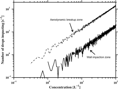
In the 1 Hz CN concentration data set, observation of a consistent enhancement due to aerodynamic breakup will require at least 1 drop per second being present in the critical flow volume. The cloud concentration corresponding to a freestream velocity of 108 m s−1 and the projected area of the sample tube lip (relevant for impaction) is ∼7 L−1, while the concentration corresponding to the aerodynamic breakup zone is 0.8 L−1. Based on these critical concentrations, it can be hypothesized that when the cloud drops present are all smaller than D crit,aero, enhancement in CN concentrations requires impaction breakup of these drops and, thus, cloud drop concentrations must be ≥7 L−1; and when cloud drops larger than D crit,aero are present, CN enhancements should become apparent at lower cloud concentrations (≥0.8 L−1).
TABLE 2 Critical breakup diameters for SDI and SMAI
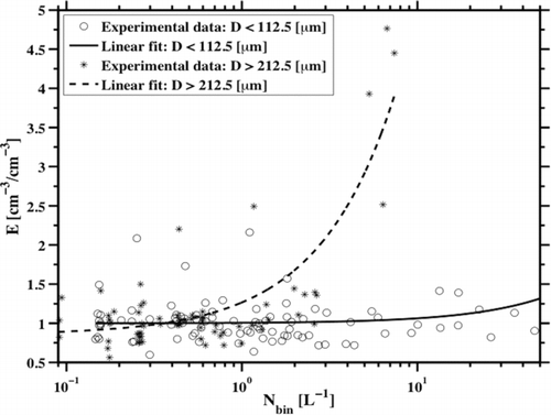
To identify aerodynamic breakup in the SMAI, sampling times were identified when only drizzle drops were present (i.e., no droplets detected by CDP) and the drop number concentrations (N bin) were calculated in two size bins: diameters, D ≤ 112.5 μm and D ≥ 212.5 μm. The CN enhancements as a function of cloud drop number concentrations for the two size ranges are shown in . For D ≤ 112.5 μm, the SMAI enhancements start to increase above 1 only for large concentrations (>10 L−1), largely consistent with the predicted critical impaction number concentration for SMAI. Thus, these drops do not shatter aerodynamically. For D ≥ 212.5 μm, CN enhancements increase significantly at concentrations >1 L−1, consistent with the prediction of aerodynamic breakup. These results provide the first direct evidence of aerodynamic breakup in airborne inlets.
FIG. 11 SMAI enhancement as a function of cloud drop concentration (N bin) in different size bins, D ≤ 112.5 μm and D ≥ 212.5 μm. In selecting data points for D ≤ 112.5 μm, a constant concentration of D > 112.5 μm was maintained (1 ± 0.25 L−1). Similarly for D ≥ 212.5 μm, the data points were selected such that the concentrations of D < 212.5 μm were constant (1 ± 0.25 L−1). Note that the exact choice of the bin concentrations did not affect the analysis.
4.2.1. Uncertainties
As the SMAI was located in the belly, for a cruise pitch of ∼ 4°, the SMAI is not expected to be in a droplet shadow region (King Citation1984). The SDI is at a distance of 30.5 cm from the skin of the aircraft and is located on the side of the aircraft, upstream of the wing. Following the analysis of King (Citation1984), it can be predicted that at the SDI location, a shadow region for droplets in the size range of 100–500 μm might exist. This shadow region, however, does not affect our analysis of SDI performance, which is largely based on impaction breakup of droplets in the size range of 10–50 μm.
For the SMAI enhancement data shown in and , the average uncertainties in E SMAI values calculated using the analysis of error propagation (Bevington and Robinson Citation2003) and assuming Poisson uncertainty in the particle number count values of the inlet and background CN are ∼4% for small cloud droplet cases () and ∼8% for drizzle cases (). Neglecting these uncertainties will, therefore, not have any bearing on the final determination of critical breakup diameters.
5. CONCLUSIONS
In summary, the critical sampling characteristics of two aerosol inlets, the SDI and SMAI, are analyzed and listed in . A conventional aerosol inlet sampling in warm clouds will experience significant cloud droplet breakup at the inlet entrance, resulting in CN measurements overwhelmed with shatter artifact particles for almost all cloud droplet sizes. The use of forward-facing diffuser type inlets that sample isokinetically is, thus, not appropriate for in-clouds measurements.
Analysis of the performance of the new SMAI inlet design suggests that this inlet is largely unaffected by the presence of cloud droplets when the mean sizes are smaller than ∼16 μm. Even when significant concentrations of droplets larger than the critical size are present, the cross-flow design of the inlet ensures that the enhancements in SMAI CN concentrations are minimal. The SMAI design provides two advantages for in-cloud sampling: its flow field is such that the critical impaction diameter is significantly increased over that of the SDI, and using a perpendicular sub-sampling tube minimizes the critical impaction area of the inlet, and thus minimizes the number of droplets impacting on the inlet. The critical impaction breakup diameter was determined from CFD simulations to be ∼20 μm, and the experimental results largely match predictions. The CFD calculations predict that the SMAI design will induce aerodynamic breakup of cloud drops larger than 100 μm and preliminary analysis of the field data confirms the role of aerodynamic breakup for droplets larger than 100 μm. The critical sampling area for aerodynamic breakup is large enough that this breakup mechanism becomes important even for low drizzle concentrations.
As the SMAI samples are seen to be shatter free or minimally impacted by shatter in the absence of drizzle, SMAI measurements can be analyzed for size distribution and composition measurements of the nonvolatile component of interstitial aerosol in a wide range of nonprecipitating cloud systems. Thus, sensitive aerosol–cloud closure studies may finally be possible. To fully establish the in-cloud sampling performance of SMAI, its measurements must be compared against other inlet designs and under different cloud conditions. Toward that goal, the SMAI was flown during a recent Ice in Clouds Experiment–Tropics (ICE-T; July 2011) campaign and its performance during those tests are compared against that of a new interstitial aerosol sampler, called the Blunt-body Aerosol Sampler (BASE), and those results will be published elsewhere (CitationMoharreri et al. in press).
Acknowledgments
The authors acknowledge funding support from NASA's Graduate Student Research Fellowship (GSRP; Cooperative agreement number: NNX09AJ08H) and NSF (AGS-1044989 and AGS-1121915). We would also like to thank Antony Clarke for the SDI data.
REFERENCES
- Andreae , M. O. and Rosenfeld , D. 2008 . Aerosol-Cloud-Precipitation Interactions. Part I. The Nature and Sources of Cloud-Active Aerosols . Earth-Sci. Rev. , 89 : 13 – 41 .
- Baron , P. A. and Willeke , K. 2005 . Aerosol Measurement: Principles, Techniques, and Applications (2nd ed.) , 1131 New Jersey : John Wiley & Sons Inc. .
- Beaton , S. P. and Spowart , M. 2012 . UV Absorption Hygrometer for Fast-Response Airborne Water Vapor Measurements . J. Atmos. Oceanic Technol. , 29 : 1295 – 1303 .
- Bevington , P. R. and Robinson , D. K. 2003 . Data Reduction and Error Analysis for the Physical Sciences (3rd ed.) , New York : McGraw-Hill .
- Cossali , G. E. , Coghe , A. and Marengo , M. 1997 . The Impact of a Single Drop on a Wetted Solid Surface . Exp. Fluids , 22 : 463 – 472 .
- Craig , L. , Schanot , A. , Moharreri , A. , Rogers , D. and Dhaniyala , S. in press . Design and Sampling Characteristics of a New Airborne Aerosol Inlet for Aerosol Measurements in Clouds . J. Atmos. Oceanic Technol. , DOI: 10.1175/JTECH-D-12-00168.1
- Denman , K. L. , Brasseur , G. , Chidthaisong , A. , Ciais , P. , Cox , P. M. , Dickenson , R. E. , Hauglustaine , D. , Heinze , C. , Holland , E. , Jacob , D. , Lohmann , U. , Ramachandran , S. , da Silva Dias , P. L. , Wofsy , S. C. and Zang , X. 2007 . “ Couplings Between Changes in the Climate System and Biochemistry ” . In Climate Change 2007: The Physical Science Basis , Edited by: Solomon , S. , Qin , D. , Manning , M. , Chen , Z. , Marquis , M. , Averyt , K. B. , Tignor , M. and Miller , H. L. Cambridge , , UK : Cambridge University Press .
- Emery , E. F. , Miller , D. R. , Plaskson , S. R. , Strapp , W. and Lillie , L. 2004 . Ice Particle Impact on Cloud Water Content Instrumentation . 42nd AIAA Aerospace Sciences Meeting and Exhibit, Jan. 2004, AIAA-2004-0731
- Ervens , B. , Carlton , A. G. , Turpin , B. J. , Altieri , K. E. , Kreidenweis , S. M. and Feingold , G. 2008 . Secondary Organic Aerosol Yields from Cloud-Processing of Isoprene Oxidation Products . Geophys. Res. Lett. , 35 : L02816
- Field , P. , Wood , R. , Brown , P. , Kaye , P. , Hirst , E. Greenaway , R. 2003 . Ice Particle Inter-Arrival Times Measured with a Fast FSSP . J. Atmos. Oceanic Technol. , 20 : 249 – 261 .
- Fluent© Inc. 2006 . “ Manual ” . Lebanon, NH,USA : ANSYS Inc. .
- Gardiner , B. A. and Hallett , J. 1985 . Degradation of In-Cloud Forward Scattering Spectrometer Probe Measurements in the Presence of Ice Particles . J. Atmos. Oceanic Technol. , 2 : 171 – 180 .
- Hinds , W. C. 1999 . Aerosol Technology: Properties, Behavior, and Measurement of Airborne Particles (2nd ed.) , 483 New Jersey : John Wiley & Sons Inc .
- Hsiang , L. P. and Faeth , G. M. 1992 . Near-Limit Drop Deformation and Secondary Breakup . Int. J. Multiphase Flow , 18 : 635 – 652 .
- Hudson , J. G. and Frisbie , P. 1991 . Cloud Condensation Nuclei Near Marine Stratus . J. Geophys. Res. , 96 : 20795 – 20808 .
- Hudson , J. G. 1993 . Cloud Condensation Nuclei Near Marine Cumulus . J. Geophys. Res. , 98 : 2693 – 2702 .
- Huebert , B. J. , Howell , S. G. , Covert , D. , Bertram , T. , Clarke , A. and Anderson , J. R. 2004 . PELTI: Measuring the Passing Efficiency of an Airborne Low Turbulence Aerosol Inlet . Aer. Sci. Technol. , 38 : 803 – 826 .
- Jensen , E. , Lawson , P. , Baker , B. , Pilson , B. , Mo , Q. and Heymsfield , A. J. 2009 . On the Importance of Small Ice Crystals in Tropical Anvil Cirrus . Atmos. Chem. Phys. , 9 : 5519 – 5537 .
- King , W. 1984 . Air Flow and Particle Trajectories around Aircraft Fuselages. I: Theory . J. Atmos. Oceanic Technol. , 1 : 5 – 13 .
- Korolev , A. and Isaac , G. 2005 . Shattering During Sampling by OAPs and HVPS. Part I: Snow Particles . J. Atmos. Oceanic Technol. , 22 : 528 – 542 .
- Lawson , R. P. 2011 . Effects of Ice Particles Shattering on the 2D-S Probe . Atmos. Meas. Tech. , 4 : 1361 – 1381 .
- Lawson , R. P. and Cooper , W. A. 1990 . Performance of Some Airborne Thermometers in Clouds . J. Atmos. Oceanic Technol. , 7 : 480 – 494 .
- Lin , S. P. and Reitz , R. D. 1998 . Drop and Spray Formation from a Liquid jet . Annu. Rev. Fluid Mech. , 30 : 85 – 105 .
- Lohmann , U. 2002 . Possible Aerosol Effects on Ice Clouds via Contact Nucleation . J. Atmos. Sci. , 59 : 647 – 656 .
- Mao , T. , Kuha , D. and Tran , H. 1997 . Spread and rebound of liquid droplets upon impact on flat surfaces . AIChE J. , 43 : 2169 – 2179 .
- McNaughton , C. S. , Clarke , A. D. , Howell , S. G. , Pinkerton , M. , Anderson , B. and Thornhill , L. 2007 . Results form the DC-8 Characterization Experiment (DICE): Airborne Versus Surface Sampling of Mineral Dust and Sea Salt Aerosols . Aer. Sci. Technol. , 41 : 136 – 159 .
- Moharreri , A. , Craig , L. , Rogers , D. and Dhaniyala , S . in review . A New Aircraft Inlet for Sampling Interstitial Aerosol: Design Methodology, Modeling and Wind Tunnel Tests . Aer. Sci. Technol. ,
- Mundo , C. H. R. , Sommerfeld , M. and Tropea , C. 1995 . Droplet-Wall Collisions: Experimental Studies of the Deformation and Breakup Process . Int. J. Multiphase Flow , 21 : 151 – 173 .
- O’Rourke , P. J. O. and Amsden , A. A. 2000 . A Spray/Wall Interaction Submodel for the KIVA-3 Wall Film Model . SAE Technical Paper 2000-01-0271 ,
- Pilch , M. and Erdman , C. A. 1987 . Use of Breakup Time Data and Velocity History Data to Predict the Maximum Size of Stable Fragments for Acceleration-Induced Breakup of a Liquid Drop . Int. J. Multiphase Flow , 13 : 41 – 757 .
- Povarov , O. A. and Rastorguev , V. F. 1986 . Liquid Drop Impact Against a Solid Surface . AIAA/ASME Joint Fluid mechanics, Plasma Dynamics, and Lasers Conference, Atlanta
- Rein , M. 1993 . Phenomena of Liquid Drop Impact on Solid and Liquid Surfaces . Fluid Dynamics Res , 12 : 61 – 93 .
- Rioboo , R. , Bauthier , C. , Conti , J. , Voue , M. and Coninck , J. 2003 . Experimental Investigation of Splash and Crown Formation During Single Drop Impact on Wetted Surfaces . Exp. Fluids , 35 : 648 – 652 .
- Rioboo , R. , Marengo , M. and Tropea , C. 2002 . Time Evolution of Liquid Drop Impact onto Solid, Dry Surfaces . Exp. Fluids , 33 : 112 – 124 .
- Rioboo , R. , Tropea , C. and Marengo , M. 2001 . Outcomes from a Drop Impact on Solid Surfaces . Atomization Sprays , 11 : 155 – 165 .
- Rogers , R. and Yau , M. 1989 . A Short Course in Cloud Physics , (3rd ed.) , 290 Pergamon Press, MA .
- Seinfeld , J. H. and Pandis , S. N. 2006 . Atmospheric Chemistry and Physics: From Air Pollution to Climate Change , (2nd ed.) , 1203 New Jersey : John Wiley & Sons Inc .
- Twohy , C. H. , Strapp , J. W. and Wendisch , M. 2003 . Performance of a Counterflow Virtual Impactor in the NASA Icing Research Tunnel . J. Atmos. Oceanic Technol. , 20 : 781 – 790 .
- Wang , A. B. and Chen , C. C. 2000 . Shattering Impact of a Single Drop onto Very Thin Liquid Films . Phys. Fluids , 12 : 2155 – 2158 .
- Weber , R. J. , Clarke , A. D. , Litchy , M. , Li , J. , Kok , G. Schillawski , R. D. 1998 . Spurious Aerosol Measurements when Sampling from Aircraft in the Vicinity of Clouds . J. Geophys. Res. , 103 ( D21 ) : 28337 – 28346 .
- Wierzba , A. 1990 . Deformation and Breakup of Liquid Drops in a Gas Stream at Nearly Critical Weber Numbers . Exp. Fluids , 9 : 59 – 64 .
- Yarin , A. L. 2006 . Drop Impact Dynamics: Shattering, Spreading, Receding, Bouncing . Ann. Rev. Fluid Mech , 38 : 159 – 192 .
- Yarin , A. L. and Weiss , D. A. 1995 . Impact of Drops on Solid Surfaces: Self-Similar Capillary Waves, and Shattering as a New Type of Kinematics Discontinuity . J. Fluid Mech. , 283 : 141 – 173 .
