Abstract
A methodology to characterize particle penetration characteristics of individual protective equipment (IPE) under elevated wind conditions was developed. Performance of a complete IPE system can be determined from the knowledge of the performance characteristics of the IPE subsystems, or components. Here, particle penetration characteristics of a cylindrical-shaped component, consisting of an outer fabric sleeve enclosing an inner appendage, were studied as a function of particle size and ambient wind conditions. A component particle penetration model was developed by combining a potential flow model to calculate flow through and around a component with a filtration model. The filtration model combines classical filtration theory with simple bench-top experiments to determine net particle penetration. The component model predictions of particle penetration through a cylindrical component suggest that its filtration performance is strongly dependent on particle size and ambient wind velocities. To test model predictions, wind-tunnel experiments were conducted over an ambient wind velocity range of 10–80 mph (5–40 m s−1) and particle diameter range of 10 nm to 2 μm. The experimental results validated model predictions of particle penetration through a cylindrical component. The component model can be extended to model the integrated IPE system considering it to be composed of a combination of cylindrical components.
Copyright 2013 American Association for Aerosol Research
INTRODUCTION
Aerosolized chemical warfare agents (CWAs) are of special concern due to their ability to be transported long distances by weather systems (Kukkonen et al. Citation2001). Harmful agents such as sarin, VX, and mustard gas can be encountered not only in their traditional gas phase, but also in a liquid aerosol phase. An additional aerosol threat is the so-called “dusty agents” which involves coating submicron sized silica particles with CWAs such as VX (Matsumoto Citation2003). These submicron aerosol CWAs can be deployed fairly easily and have small enough particle sizes to penetrate standard air-permeable protective fabrics. In addition to chemical agents, harmful biological substances such as anthrax also exist in aerosol form.
To protect against harmful aerosols, any air-permeable protective fabric must act as a particulate filter. The individual protective equipment (IPE) fabric studied for this research consists of an outer tightly woven layer backed by an activated carbon inner layer, which is designed to filter out harmful vapors. The fibers, primarily in the outer woven layer of fabric, provide majority of the air flow resistance and particulate filtration. The interaction of the IPE fabric with particles is similar to that of filter media and, thus, traditional filtration theory can be used to analyze the performance of IPE fabric in filtering out particles directed toward them.
Although aerosol filtration is an extremely important factor pertaining to the design of the IPE fabric, since harmful biological and chemical substances could be deployed as aerosols, little research has been performed to quantify the filtration performance of this material. The man-in-stimulant test (MIST) (Dugway Proving Ground Citation1996) tests the entire IPE system on a person, simulating a real life scenario. The MIST procedure is an overall IPE performance standard; subsystem tests, also known as component tests, are, however, needed to quantify the performance of individual pieces of the IPE for design analysis. Previously, swatch tests were used to quantify aerosol penetration of IPE fabric (U.S. Army Dugway Proving Ground Citation1997). In a swatch test, a piece of fabric is placed in a closed environment and air is forced through the material. The drawback of this method is that in a real world environment, air has the ability to flow around and is not forced though the fabric.
Here, a simple approach to model the filtration characteristics of a component is presented and an experimental method to test component performance is established. Three main sets of experiments were performed to aid development and testing of the component particle penetration model; a bench-top filter-holder test to establish the filtration efficiency and permeability of the IPE fabric; a swatch test to determine the performance of the fabric piece in a wind tunnel; and finally a sleeve component test to validate model predictions.
MODELING APPROACH
An IPE system must provide protection for an individual from airborne agents under a range of wind conditions. A full IPE system may be composed of individual components or subsystems such as, body suit, face mask, gloves, etc. as illustrated in . A capability to predict the protective ability of the entire IPE system as a function of the IPE fabric material and ambient conditions will help determine the threat level to an individual or group on exposure to airborne agents. Also, such a capability will enable optimization of the design of the components or their fabric material properties for best protective performance.
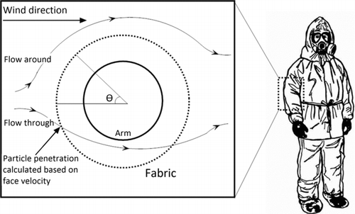
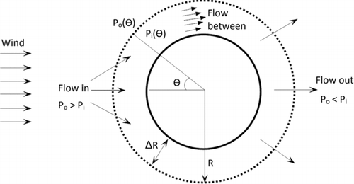
In this study, particle penetration characteristics of a sleeve component as a function of the directed ambient wind speed was investigated (illustrated in ). To model this system, the sleeve was idealized as a rigid, permeable cylinder, and the appendage on the inside as a solid cylinder. The component test was modeled in two steps. First, the flow through the fabric caused by the wind was predicted as a function of the angular (θ) locations. From the prediction of the local normal velocity (i.e., face velocity at any, angular location, Vf (θ)), particle penetration was estimated as a function of particle diameter using filtration theory. This approach is consistent with that of nonuniform filtration theory of Dhaniyala and Liu (Citation2001a,Citationb).
If fabric deformation can be ignored, potential flow assumption can be used to determine static pressure on the fabric surface of the simple cylindrical sleeve component geometry flow [Po(θ)]. To relate the flow inside the fabric sleeve to the external pressure distribution, the flow in the gap (ΔR) between the fabric and the inner cylinder was assumed to have a parabolic flow profile, and from mass conservation for the flow through the fabric and the flow in the gap and considering momentum conservation along the θ direction, the following equations were obtained:
(1)
(2) where Pi(θ) is the pressure inside the fabric, μ is gas viscosity, α is fabric permeability, and R is the radius of the fabric cylinder. This formulation is based on the approach of Li et al. (Citation2001) and is illustrated in . The pressure drop across the fabric at circumferential location θ was obtained as:
(3) where V∞ is the free stream velocity, and ρ is the gas density.
To calculate air flow characteristics through and around the component test geometry, flow simulations using a computational fluid dynamics (CFD) approach can be used. Such simulations will help account for complex geometries and a range of media properties. But such simulations are complicated and will require significant computational time.
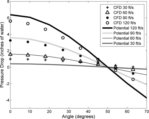
CFD calculations using the software FLUENT 6.3.26 (Fluent Inc., NH, USA) were used to test the predictions of the simple potential flow model. In the CFD simulations, a porous jump boundary condition was used to represent the fabric media, and the component was located in a wind-tunnel with velocity inlet and outflow conditions at the entrance and exit, respectively. For the porous jump boundary condition, the permeability of the media must be input, and this was obtained from experimental measurement of fabric pressure drop as a function of face velocity, as described later.
The pressure drop (Po–Pi) across the fabric at four different free stream velocities were calculated using the potential flow model and compared with CFD simulations in . For angles smaller than ∼50o on the upstream side of the cylinder, where the flow enters the component, the potential flow and CFD results were in reasonable agreement (), with the small differences being insignificant with respect to particle penetration calculation. The maximum pressure drop, and hence flow rate, was at the fore of the fabric cylinder due to the dynamic pressure component of the free stream flow. For angles larger than 50o, i.e., where the flow exits the component, the potential flow predictions begin to differ from CFD results. As penetration predictions only require accurate characterization of flow entering the component, the potential flow model should suffice for this case.
The component particle penetration model was developed by combining potential flow calculations with a particle filtration model. In this approach, bench-top tests were used to obtain particle penetration data for the fabric media of interest for a range of operating conditions. The single fiber filtration efficiency (EΣ) can be obtained from the classical filtration theory (Davies Citation1973), as:
(4) where, Vf is face velocity, Dp is particle diameter, B1–4 are media-dependent constants, ER, EI, ED, and EDR (Equation (5)) are filtration efficiencies due to interception (Stechkina and Fuchs Citation1966), impaction (Langmuir Citation1948), diffusion (Davies Citation1973), and diffusion-enhanced interception (Stechkina and Fuchs Citation1966), EΣ is the net single fiber filtration efficiency. The single fiber efficiencies due to the different mechanisms were calculated as:
(5) where Pe is the Peclet number, Stk is particle Stokes number, R is the interception parameter, and Ku is the Kuwabara constant. The interception parameter is the ratio of the particle diameter to the fiber diameter and the Kuwabara constant (Liu and Rubow Citation1986; Matteson and Orr Citation1987) can be calculated as:
(6) The total filter efficiency (η) can then be calculated as:
(7) where α is packing density, t is the media thickness, and df is the average fiber diameter of the filter media.
Flow through woven media has often been modeled on two different fiber scales, the multifiber yarns and the intrayarn fibers. Goodings (Citation1964), Breard et al. (Citation2003) and Wang et al. (Citation2006) all model flow through the fabric with varying pore sizes. The filtration model of Benesse et al. (Citation2006), uses two different single fiber efficiencies for the yarn and the fibers. The IPE material is, however, very tightly woven, making any flow between the yarns negligible and the entirety of the flow can be assumed to pass through the yarns and between the fibers (Gibson et al. Citation1999). For the fabric media under test, an estimate of the fiber diameter was obtained from scanning electron microscope (SEM) analysis. Based on the measured fiber diameter, the packing density (α) can be calculated using fabric permeability (Davies Citation1973), or other theoretical approaches (Dhaniyala and Liu Citation1999b). For known fabric media properties, the constants B1–4 can be calculated from bench-top experimental results of fabric penetration as a function of particle size and face velocity using a multivariate analysis. Thus, an expression for the net filter efficiency or penetration can be obtained as a function of particle size and flow velocity for a selected media.
The local pressure drop across the fabric located on the cylindrical component holder can be calculated using the potential flow model and the local face velocity [Vf (θ)] can be obtained from the pressure drop calculations assuming constant local media permeability. For uniform upstream particle concentration, the net particle penetration through the component (1-η) can then be obtained as the ratio of net particle flux passing through the fabric media to the particle flux directed toward the component holder:
(8) where θ1 and θ2 are the angles corresponding to the limits of the region through which the flow enters the cylindrical component. In EquationEquation (8)
(8) , the numerator represents the net particle penetration flux accounting for local filtration efficiencies and local flow flux. For a selected particle diameter and a known local velocity, the local penetration [1−η(Vf(θ), Dp)], can be obtained from bench-top measurements of fabric efficiency (EquationEquation (7)
(7) ). The net penetration can then be calculated as a function of face velocities and particle sizes and compared with experimental results.
EXPERIMENTAL PROCEDURE
Bench-Top Tests
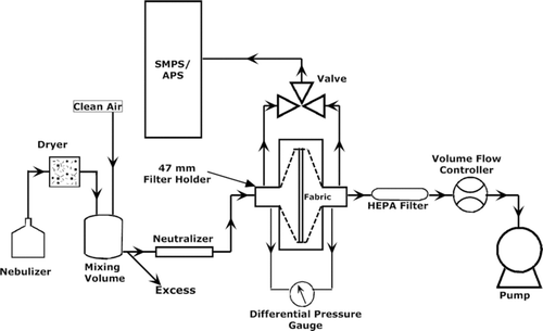
To develop the fabric filtration model described above, the variables B1–4 (EquationEquation (4)(4) ) must be obtained from bench-top penetration data. A schematic diagram of the experimental setup used for these tests is shown in . Aerosol particles were generated by nebulizing a solution of dioctyl sebacate in isopropanol. The aerosol particles were passed through a desiccant dryer and into a 5-gallon mixing chamber. In the mixing chamber, clean air was introduced to dry the aerosol and dilute the concentration. The large volume of the mixing chamber allowed for temporal stability of the aerosol source, critical for accurate penetration measurements. After exiting the mixing chamber, the aerosol was passed through a Kr-85 neutralizer (TSI 3077) to charge neutralize the particles before they were passed to the filter holder. The test fabric was located in the 47 mm filter holder, and penetration measurements were obtained from particle concentration measurements made upstream and downstream of the fabric. Particle concentrations were measured using two instruments: a scanning mobility particle sizer (SMPS) for particles in the size range of 10–500 nm; and an aerodynamic particle sizer (APS; TSI 3321) for particles in the size range of 500 nm to 2 μm. The face velocity through the fabric was controlled using a volume flow controller and a vacuum pump downstream of the filter holder. The pressure drop across the filter was monitored to ensure that the filter was not loaded during the measurements.
The experimental setup shown in was used for both penetration and permeability measurements. To measure penetration, upstream and downstream particle concentration measurements were made as a function of particle size and face velocity. For the permeability measurements, the aerosol generation and sampling systems were removed from the setup and only the differential pressure was monitored with varying flow rates trough the filter holder. The fabric permeability was determined from pressure drop measurements across the fabric as a function of face velocity.
Swatch Tests
Prior to running a full component test in the wind tunnel, it was critical to validate the performance of the wind-tunnel aerosol injection and sampling systems. For this, a small piece of fabric (swatch) was located perpendicular to the flow in the tunnel cross-section, upstream of a chamber that is designed to control the face velocity through the fabric. This test, called the swatch test, was similar to the bench-top experiments with the face velocity through the fabric being controlled with a pump rather than the wind. Consistent results from the swatch-holder and bench-top experiments provide confidence in the injection and sampling systems used for wind-tunnel experiments.
A schematic diagram of the experimental setup used for the swatch tests is shown in . Similar to the bench-top experiments, test aerosol particles were generated using nebulizers. Four nebulizers were used in parallel to ensure that the particle number concentrations in the tunnel were sufficient for penetration measurements. A mixing chamber was used to ensure temporal concentration uniformity of the generated aerosol. Particles were injected into the wind tunnel using an array of 12 injection ports, spread over an area of 3″ × 3″. The injection grid was covered with a coarse screen to facilitate turbulent mixing, and hence spatial uniformity, of the injected aerosol in the wind tunnel. The particles were then carried to the swatch by the wind, and particle concentrations upstream of the fabric holder were measured using a ¼″ O.D stainless steel tube placed ½″ in front of the swatch.
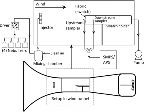
The swatch holder consisted of a 3′ long, 3½″ I.D tube with the fabric sample attached at the front of the holder. Internal circumferential pressure ports allowed monitoring of pressure drop across the fabric, to ensure that particle loading was not a factor in the penetration measurements. At the rear of the swatch holder, a vacuum pump was connected to draw a required flow rate consistent with the desired face velocity. For downstream concentration measurements, flow was sampled from inside the swatch holder using a ¼″ O.D sample tube 6″ downstream of the swatch. Subsequent testing revealed that the exact location of the downstream sample port inside the swatch holder was not important in determining downstream concentrations. Similar to the bench-top test, upstream and downstream particle size distributions were measured using a SMPS and an APS.
Component Tests
The wind-tunnel aerosol generation and sampling systems for the component tests were identical to that used in the swatch tests. The component holder consisted of a cylindrical fabric sleeve holder of 4⅜″ diameter, which is the standard sleeve size for the IPE, surrounding a solid inner cylinder of diameter 3¼″, representing a human arm (). In the component holder, two sampling tubes were located in the ![]() ″ gap between the cylinders for particle concentration measurements—one flush with the inner cylinder surface and the other located midpoint between the inner cylinder and the fabric. These sample tubes were used to determine the effect of radial sampling location on the measurement of downstream particle concentration. Pressure measurement ports were also located just inside and outside of the sleeve for pressure-drop measurements. The pressure ports were oriented vertically, flush against the fabric to measure static pressures at the desired locations. The pressure drop measurements across the fabric were used to calculate local face velocities for varying ambient wind conditions and angular positions on the fabric cylinder.
″ gap between the cylinders for particle concentration measurements—one flush with the inner cylinder surface and the other located midpoint between the inner cylinder and the fabric. These sample tubes were used to determine the effect of radial sampling location on the measurement of downstream particle concentration. Pressure measurement ports were also located just inside and outside of the sleeve for pressure-drop measurements. The pressure ports were oriented vertically, flush against the fabric to measure static pressures at the desired locations. The pressure drop measurements across the fabric were used to calculate local face velocities for varying ambient wind conditions and angular positions on the fabric cylinder.
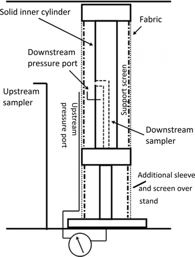
Under realistic scenarios, a fabric sleeve in wind will deform and flutter. Thus, particle penetration through the sleeve under such conditions will be a combination of the spatial and temporal distribution of the penetrating flow fields and the resulting particle paths. While the eventual goal is to model such a system, a preliminary model that explains the interaction of ambient wind and particle paths must first be established. To prevent fabric deformation and fluttering at high wind speeds, a support screen just inside the fabric sleeve cylinder was used (). This artificial constraint on the fabric geometry provided a simple baseline case for comparison of experiment results with the CFD and potential flow modeling predictions. To eliminate any three-dimensional flow effect in the wind tunnel, the stand at the bottom of the component holder was also covered with a fabric and a support screen ().
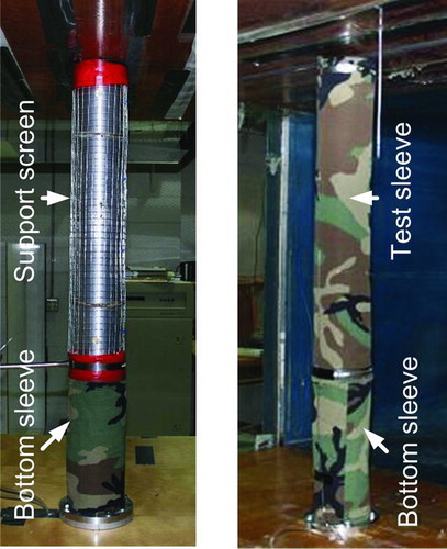
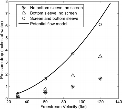
To determine the effect of the support screen and the bottom sleeve covering the stand, pressure drop measurements were made across the fabric at the front of the cylinder (θ = 0°) for different configurations (). The presence of the screen and extension of the sleeve over the entire height of the cylinder was seen to result in pressure drop measurements that matched modeling results. Penetration measurements were then made with this configuration for a range of wind speeds and particle sizes.
RESULTS AND DISCUSSIONS
Bench-Top Tests
Bench-top filter holder tests were performed at four different fabric face velocities, ranging from 6.5 to 27 cm s−1. The range of face velocities represented the limits of the experimental setup. The minimum flow rate required by the sampling instruments (without external dilution for measurements) resulted in the minimum face velocity of 6.5 cm s−1, and for face velocities greater than 27 cm s−1, the pressures in the filter holder were too low for the sampling instruments. The penetration measurement results for the four different face velocities are plotted in . From the general shape of the penetration curves, the IPE fabric was seen to behave similar to traditional filtration media (Dhaniyala and Liu Citation1999a).
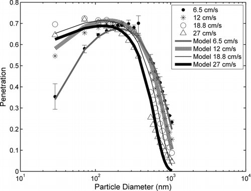
Increasing the face velocity increased the penetration of small particles and decreased the penetration of larger particles. This is because, at higher face velocities particle capture by diffusion becomes less important, permitting more small particles to pass through the fabric. Also, at higher face velocities, the particle Stokes numbers increase, and the capture of larger particles (those with Stokes number > ∼ 1) by inertial impaction is enhanced. Based on least squares analysis of the bench-top experimental data, the expressions for variables B1–4 were obtained as:
(9) The variables B1 and B2 are seen to be constant, while B3 and B4 are dependent on face velocity. Combining EquationEquations (4)
(4) and Equation(7)
(7) , the particle penetration through a selected fabric media can be expressed as a function of particle diameter and fabric face velocity. A simple comparison of the predictions of the fabric penetration model with the bench-top experimental data for the four different face velocities is shown in . As expected, the filtration model agreed well with the experimental data that were used to generate the model.
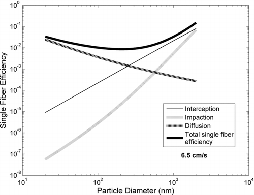
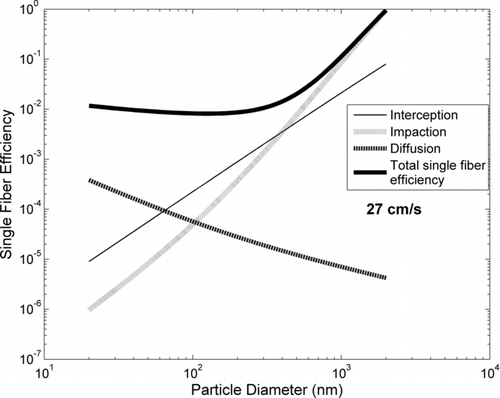
The contributions of diffusion, interception, and impaction on the total single fiber efficiency of the fabric media are illustrated in and . For a low face velocity (6.5 cm s−1), diffusion was the main capture mechanism for small particles and interception was the main mechanism for large particles. With increasing face velocity, the particle residence time in the media decreased and hence the diffusional capture of small particles decreased. When the face velocity was increased to 27 cm s−1, the Stokes number increased and impaction played a much larger role.
Swatch Tests
The swatch tests were conducted to establish the wind-tunnel injection and sampling systems, and to investigate if fabric penetration characteristics at a constant face velocity were independent of free stream velocity. Initial penetration tests were performed at near isokinetic conditions with no swatch (fabric) in the swatch holder. The objective of this test was to determine if there were any systematic differences in the upstream and downstream measurement systems. Because of the upper limit of our vacuum pump capacity and the lower limit of the wind-tunnel operation, exact isokinetic conditions could not be achieved. The vacuum pump was able to provide a maximum swatch holder face velocity of approximately 0.3 m/s, and the wind tunnel was able to provide a minimum stable free stream velocity of 0.6 m/s (2 ft/s). In these experiments, for 15 particle diameters ranging from 30 to 300 nm, an average penetration of 0.97 with a standard deviation of 0.04 was observed, providing initial validation of the wind-tunnel injection system.
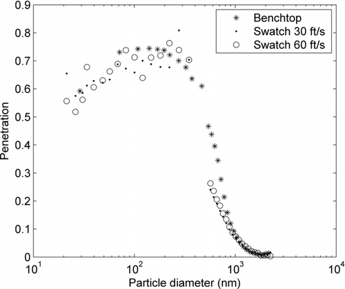
The next tests were with the swatch in place at the entrance of the swatch holder. The swatch penetration measurement results for two different free stream wind speeds (30 and 60 ft/s) are shown in . Also shown in are bench-top results for the equivalent face velocity (27 cm s−1). The results suggest that there was no discernible effect of free stream wind velocity on particle penetration when the fabric face velocity was constant. The independence of penetration on free stream velocity was consistent with the small Stokes numbers of the test particles, calculated based on the fiber diameter and free stream velocity. The swatch-holder test results, therefore, provided further validation of the wind-tunnel injection and sampling systems.
Component Tests
The LLC potential flow model was used to determine face velocities through the component cylindrical fabric sleeve as a function of angular position, and the face velocities were combined with the filtration model to determine the net particle penetration Equation(Equation (8))(8) through the component as a function of free stream velocity. The model predictions in comparison with experimental results of particle penetration for the component model are shown in for four free stream velocities ranging from 30 to 120 ft/s.
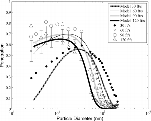
Particle penetration characteristics of the IPE component sleeve depended significantly on free stream velocities. At low wind speeds, the diffusional capture mechanism dominated and particles smaller than 50 nm were efficiently captured, but larger particles (∼1 μm) penetrated through the fabric as they were not effectively captured either by diffusion or inertial impaction. Particles larger than 2 μm were effectively captured by the IPE fabric over the entire range of wind speeds studied (30–120 ft/s) due to their large size and Stokes numbers by the mechanisms of interception and impaction. As wind speeds were increased, the inertial capture of particles shifted to smaller sizes. At high wind speeds, however, the residence time of particles in the region closest to the fibers was reduced, and thus diffusional capture efficiency decreased. For the fabric media studied, the model suggests that peak particle penetration occurs for wind velocity in the range of 90–120 ft/s. However, considering the air flow rate through the fabric, the total particle flux passing through the fabric increased with increasing wind speed.
To validate the results of the model, penetration measurements of the component sleeve were made at free stream velocities of 30, 60, 90, and 120 ft/s in the wind tunnel. For valid experimental results, it was important to ensure that the flow flux and particle penetration through the component fabric was only dependent on the ambient wind velocities and not on the sampling flow rate of the particle instruments downstream of the swatch. For this, penetration measurements were obtained with different flow rates through the downstream sample probe and it was observed that there was no change in particle concentrations downstream of the fabric, suggesting that the instrument sample flow rates were significantly smaller than the ambient wind-driven flow flux. The effect of the θ location of the downstream sampler was also investigated. It was found that the location angle of the sampler made a difference in the measurement of downstream particle concentration, suggesting the air volume between the outer fabric cylinder and the inner cylinder was not well mixed. As there are no likely mechanisms for enhancement of particle concentration inside the component holder, the final location of the probe was chosen based on where the maximum penetration value was obtained (θ = ∼30o–60o).
The uncertainty in the penetration measurements was maximal for small particles due to the choice of generated aerosol size distribution and the measurement technique. To ensure sufficient aerosol concentration over the entire test size range, the test aerosol was generated with a mean size ∼300–500 nm, resulting in fewer particles in the smaller size range. Also, for fast measurement, the SMPS scan time was set to 2 min and 10 diameter channels, resulting in only a 12 s sampling time per diameter channel. For larger particles, measurement with the APS was made over a 1 min interval, resulting in better counting statistics of these particles. The error estimates based on counting statistics were also consistent with the variability in the measurements.
Over the entire size range, the experimental results compared well with the predictions of the component penetration model that was obtained by combining the potential flow and the filtration models. As predicted, because of diffusional capture, particle capture efficiency was greater at lower wind speeds. Maximum penetration was seen to occur at a wind speed of 90 ft/s, with capture by impaction causing the penetration to decrease from 90 to 120 ft/s.
SUMMARY AND CONCLUSIONS
The use of IPE for protection against particle exposure requires the knowledge of their performance over a range of operating conditions. Here, we present a simple approach to model the performance of an IPE fabric component as a function of particle diameter and directed wind velocity. Bench-top experiments suggest that the IPE fabric behaves like standard filtration media, and that its performance can be modeled using traditional single fiber efficiency theory. The nonstandard characteristics of the fabric, such as the woven structure and the multiple layers, were accounted for as media-specific parameters in the penetration equation, which were determined from simple bench-top experiments. For experimental tests of the IPE component performance, a wind-tunnel aerosol injection system was developed and this system was seen to provide temporally and spatially uniform particle concentration in the test section, which allowed for accurate penetration measurements.
A component sleeve model was developed by combining a potential flow model with nonuniform filtration theory. The flow model is simple and idealized, and was used to determine local pressure drops, and hence local face velocities, across the cylindrical component fabric sleeve based on experimentally determined permeability values. The nonuniform filtration model, with parameters obtained from a small number of bench-top experiments, can then be combined with the potential flow model to calculate net particle penetration through the component fabric sleeve caused by ambient winds. The model predictions of particle penetration through a component sleeve, as a function of particle size and face velocity, matched well with wind-tunnel measurements. The experimental and theoretical approaches can be extended to characterize particle penetration through full suit IPE systems.
The authors kindly acknowledge funding from the Defense Threat Reduction Agency (DTRA; Agreement # SEA 139).
REFERENCES
- BreardJ.HenzelY.TrochuF.GauvinR.2003243391408
- BenesseM.CoqL.L.SolliecC.200637974989
- DaviesC.N.Air Filtration Academic Press New York 1973 ISBN 0-12-205660-4
- DhaniyalaSLiuB.Y. H.1999a4213240
- DhaniyalaS.LiuB.Y. H.1999b30333348
- DhaniyalaS.LiuB.Y. H.2001a342161169
- DhaniyalaS.LiuB.Y. H.2001b342170178
- GibsonP.DonaldR.CyrusK.HeidiS.-G.199969311317
- GoodingsA.C.196434713724
- KukkonenJ.RiikonenK.NikmoJ.JappinenA.NieminenK.2001853165179
- LangmuirI.19485175192
- LiL.LiuJ.ChengD.200162559562
- LiuB.Y. H.RubowK.L.Air Filtration by Fibrous Media. Fluid Filtration: Gas American Society for Testing and Materials Philadelphia 1986
- MatsumotoG.200330214921497
- MattesonM. J.OrrC. et al.Filtration: Principles and Practices Marcel Dekker, Inc New York 1987
- StechkinaI.B.FuchsN.A.196695964
- U.S Army Dugway Proving GroundFinal Report for the Development of the Man-in-Simulant Test (MIST) Methodology for Evaluation of Chemical/Biological (CB) Protective Garments Utah 1996 TECOM project No. 8-EI-825-ABO-004, Dugway
- U.S Army Dugway Proving GroundPermeation of Air-Permeable, Semipermeable and Impermeable Materials with Chemical Agents or Simulants (Swatch Testing) Utah 1997 TOP 8-2-501, Dugway
- WangQ.MazeB.TafreshiV.PourdeyhimiB.20066180858088
